Abstract
This work reviews the transition from hyperthermia to ablation for cancer treatment with interstitial microwave (MW) antennas. Early work utilising MW energy for thermal treatment of cancer tissue began in the late 1970s using single antennas applied interstitially or the use of multiple interstitial antennas driven with the same phase and equal power at 915 or 2450 MHz. The original antenna designs utilised monopole or dipole configurations. Early work in thermal therapy in the hyperthermia field eventually led to utilisation of these antennas and methods for MW ablation of tumours. Efforts to boost the radiated MW power levels while decreasing antenna shaft temperatures led to incorporation of internally cooled antennas for ablation. To address larger tumours, MW treatment utilised arrays that were simultaneously activated by either non-synchronous or synchronous phase operation, benefiting both hyperthermia and ablation strategies. Numerical modelling was used to provide treatment planning guidance for hyperthermia treatments and is expected to provide a similar benefit for ablation therapy. Although this is primarily a review paper, some new data are included. These new data show that three antennas with 2.5 cm spacing at 45 W/channel and 10 min resulted in a volume of 89.8 cm3 when operated synchronously, but only 53.4 cm3 non-synchronously. Efficiency was 1.1 (synchronous) versus 0.7 (non-synchronous). MW systems, treatment planning, and image guidance continue to evolve to provide better tools and options for clinicians and patients in order to provide better approach and targeting optimisation with the goal of improved treatment for the patient.
Introduction
Microwave (MW) interstitial applications have been in use and under development since the late 1970s. Early reports by Taylor Citation[1], Citation[2] described the use of a MW syringe through which electromagnetic energy was ‘injected’ into a tumour. The radiator had two unique features for its time: irradiation of deep biological structures by simple needle injection and simultaneous chemotherapeutic treatment of tissue Citation[3]. This was one of the first studies to suggest that a MW antenna could be inserted into a tumour to destroy it with heat alone. Early work by Strohbehn et al. Citation[4] demonstrated a sharp tip antenna inserted directly into tissue powered at 3–10 W with microwaves in the frequency range 500–1300 MHz. They suggested that it may be possible to treat with much higher temperatures if the heat source was well-localised in the tumour. The antennas were monopole designs with a quarter-wavelength tip section. They evaluated the system with heat alone or with radiation and/or chemotherapy by insertion directly into the tumours (as described below) Citation[4]. Further studies by Douple et al. Citation[5] investigated thermal distributions produced by this system using 1 GHz microwaves in a tumour model composed of mammary adenocarcinomas (MTG-B) implanted in thighs of C3H mice. The therapeutic efficacy of hyperthermia was demonstrated by comparing tumour diameters in mice following control, sham, or hyperthermia treatment. The results verified that this system could be employed clinically to provide localised hyperthermia in deep-seated tumours Citation[5].
Early reports of therapeutic temperatures during microwave treatments were reported to be 44°–45°C for 20–30 min, correlating well with later studies Citation[6]. Initial sites for treatments with heat alone were brain and liver, however, most of the subsequent work in the field focused on combining MW therapy with interstitial radiation therapy (brachytherapy) as hyperthermia. The procedure involved intratumoural placement of plastic catheters into which both the ionising radiation sources and the MW antennas would be alternately inserted. In this combination therapy, the MW heating was used to boost the effectiveness of the radiation treatment. Accordingly, tissue temperatures achieved were between 42° and 50°C Citation[7]. Interstitial hyperthermia for localised cancer was found to effectively heat tumours and provide local control Citation[7–14] and significantly boost the effectiveness of both radiation therapy and chemotherapy in randomised trials Citation[7], Citation[15], Citation[16]. No difference was seen in radiation with or without heat for complete response if the hyperthermia treatment did not meet its temperature goals of 42.5°C for 45 to 60 min in the entire tumour Citation[17].
As interstitial techniques evolved, single antennas were found to heat only a small volume and thus an array of antennas was necessary to adequately treat typical tumour volumes Citation[18]. Due to rapid falloff of power from a single antenna, temperature gradients of 5°–8°C/mm were found in well-perfused tissues such as brain. To achieve a target of 42.5°C at 7.5 mm, 62°C was needed at the antenna source in canine brain Citation[19].
Arrays of antennas were developed and tested. Advantages were found with certain designs such as the symmetrical dipole. It had a phase relationship between antennas such that through constructive interference, power deposition and specific absorption rate (SAR is power deposition in W/kg; often normalised to isoSAR contours, expressed as a percentage of maximum) was greatest in the centre of the array volume. When normalised, this central value was found to be 80% SAR in both theory and experimental work Citation[18]. Arrays allowed conformability to irregular tumour volumes and tumours deep within the body Citation[20] by both flexibility in placement and in the selection of the number of antennas implanted. MW hyperthermia was generally performed at precisely controlled target temperatures for specified treatment times ranging from 30 to 60 min. In the early stages of MW therapy, the term hyperthermia included elevated temperatures that exceeded normal body temperatures, including temperatures reaching and exceeding 60°C. As the designs of the MW antennas evolved and input power was increased and combined with image-guided placement, it became possible to treat tumours sufficiently with heat alone as an ablation modality. Recent clinical trials have shown therapeutic MW use over a range of anatomical sites: fibroids Citation[21], lung, kidney Citation[22], bone, pancreas, adrenal glands Citation[23], chest wall Citation[24], liver Citation[25–27], brain Citation[7], Citation[10], and prostate Citation[12], Citation[28]. This paper describes the progression from hyperthermia to ablation (coagulation) with both technology and treatment methods, as well as early clinical results.
Development of MW antennas and thermal therapy
Validation of MW performance
During these early developments in the field, hyperthermia was understood to produce elevated heat treatment of tissue, particularly targeting cancerous tumours. In 1979 animal studies were performed showing coagulation necrosis of swine liver by a phase-coherent MW interstitial array, leading to the introduction of one of the first commercial systems which was BSD-1000 (BSD Medical, Salt Lake City, UT) Citation[29], Citation[30]. Other commercial systems arrived in 1982: Mark I (Clini-Therm, Dallas, TX) Citation[31], System 100 (Cheung Labs., Columbia, MD) Citation[32], and Intertherm 100 (Labthermics, Champaign, IL) Citation[33]. All of these systems had interstitial MW antennas with manual control of power and some had temperature feedback control of power.
One goal of the early animal and clinical studies was to obtain more uniform temperatures within a tumour to enhance the effectiveness of radiation therapy. Since improved uniformity in temperatures would provide better hyperthermia treatments, added control was provided with a second-generation commercial system which was introduced in 1984 (BSD-500). This system provided eight individually controlled MW power channels based on temperature sensor feedback to automatically control target site temperatures with power control using feedback from either independent temperature sensors or sensors integrated into microwave interstitial antenna for more conformable array heating Citation[34]. This system provided up to 60 W per channel typically supplying 25 W per applicator and was used for microwave interstitial thermal ablation of prostate cancer Citation[12]. This early clinical system delivered power synchronously and included a numerical model for the interstitial array such that the SAR pattern of a particular antenna implant could be visualised for pretreatment planning Citation[35], Citation[36].
Early 3D analytical models Citation[37], Citation[38] were predecessors for finite element models (FEM) Citation[39]. This work with 3D numerical SAR predictions of interstitial phased arrays showed that 915 MHz was advantageous for such arrays because of antenna length and improvement in central heating Citation[36–39]. Some of the early ablation work was seen in clinical studies from 1986 to 1996 using MW heating at thermal therapy temperatures to treat benign prostate disease. This led to a great number of published studies as thermal therapy was adopted as standard practice in urology for the treatment of benign prostatic hyperplasia (BPH) Citation[8], Citation[40], Citation[41].
There were many clinical studies in Japan (dating from 1986 to 2009) Citation[39] based on the use of a single, rigid MW antenna which they termed percutaneous microwave coagulation therapy (PMCT). These dipole or monopole antennas had a centre conductor connected to the antenna tip and a small dielectric gap separating the outer conductor between antenna segments. They were directly inserted into the tumour a number of times to provide full coverage of the target Citation[42], Citation[43]. These early efforts demonstrated the successful use of small, sharp-tip antennas for ablation in clinical applications and established a basis for current MW ablation therapies. The studies also incorporated methods using 60 W of power during withdrawal, in order to coagulate the antenna insertion track to prevent bleeding and tumour cell seeding Citation[44]. A review article of the developmental history of MW ablation methods and practices may provide more details Citation[45]. By the year 2000, the practice of percutaneously inserted, sharp needle microwave antennas for coagulation therapy with internal water flow cooling was in clinical practice and being commercially sold within China to treat cancerous tumours Citation[46].
MW numerical solutions
The electromagnetic (EM) field theory of the insulated dipole antenna was fully developed by King et al. Citation[47]. Following this, Trembly Citation[38] developed the theory of the linear, insulated antenna array embedded in an electrically dense medium for cancer therapy. His work showed that the most efficient power deposition in tissue occurred when the dipoles were at resonant length. Although lower frequencies of 500–700 MHz deposited more energy centrally, the lengths of the antennas made them impractical for tumour treatment. Use of antennas designed for 915 MHz provided a practical length when considering the range from 300–915 MHz Citation[38].
MW antenna design evolution
The original designs of antennas were monopoles or dipoles. Variations on this design included one that had a series of in-line sleeves, wider, then narrower, then wider again, to entrance the EM field and extend the heating pattern Citation[48]. One study compared dipole antennas and the aforementioned enlarged tip antennas in arrays and found that the enlarged tip provided a larger volume of heating, as indicated by the 50% isoSAR Citation[49].
An alternative design, scaled down from communication antennas was the helical antenna with a wound helix on part of the antenna, usually the tip section. Helical antennas were fabricated at Dartmouth College and shown to give improved localisation of heating over a range of insertion depths Citation[18]. In addition, longer or shorter lengths were fabricated to alter axial heating lengths at a single frequency. This gave more flexibility than a dipole antenna at 915 MHz Citation[50] and produced less heating at the insertion point when used in vivo Citation[51]. A numerical model was also created Citation[52], showing good correlation of simulations to measured results. There were several other variations and hybrids including modified dipoles with a helical tip that successfully combined the phase relationship of a dipole and the tip-heating of a helical antenna Citation[17]. These had improved performance in arrays when compared to a helical array. There are other more recent MW antenna designs that have been reported Citation[14], Citation[46], Citation[61–63] and a retrospective article is available comparing various designs Citation[58].
MW antenna cooling
Cooling was added to MW antennas to preserve tissue in the vicinity of an antenna (i.e. urethra in prostate heating) or to cool the shaft at the proximal end which could be a sensitive, skin exit point. Cooling was accomplished with either fluid or with rapidly flowing air. Cooled antenna functionality at 433 MHz Citation[59] and 915 MHz Citation[60] was demonstrated in preclinical trials. Another antenna operating at 915 MHz applied localised MW hyperthermia to the prostate in dogs using a water-cooled antenna designed for the treatment of human prostates. The prostate glands of 20 male dogs were heated repeatedly, under general anaesthesia, at temperatures between 40°C and 47°C, up to 10 h. Permanent tissue damage was found to be time and temperature dependent. Heating at 42.5°C (±0.5°C) for up to 1.5 h was well tolerated Citation[60]. Sharp tip antennas that had built-in cooling were also successfully used in arrays in prostate cancer. Helical antennas were also used with active cooling for conformable heating of tumours after basic, homogeneous pretreatment planning Citation[61–63].
Kuang et al. Citation[53] showed new antenna designs for percutaneous use with a 14-gauge shaft cooled by 4°C saline. The shaft was 10°C during the ablation and it was compared at 60 W and 5 min with and without cooling. With no cooling, heat tracked up the shaft and the ablation shape had a tail. With cooling, the ablation was more spherical and had no tracking up the shaft. Ablation diameters for cooled antennas were: 3.5 × 5.9 cm (1 antenna, in vivo); 5.4 × 6.7 cm (2 antennas, in vivo); 3.6 × 5.9 cm (1 antenna, human tumour); 4.8 × 5.7 cm (2 antennas, human tumour); and 6.4 × 8 cm (3–4 antennas, human tumour) Citation[53]. The cooled antenna shaft eliminated skin burns and allowed larger ablation volumes (using greater energy, power, and time) for percutaneous insertion.
Most recently, an intricate numerical model was created and then compared to experimental results with good agreement for a single, cooled, MW dipole antenna (1.9 mm diameter, 60 W, 2450 MHz). There was excellent overlap of the 54°C isotherm which appeared to be an indicator of the ablation boundary. The maximum radius of 12 mm was not affected by the antenna cooling parameters if the power was maintained constant. The cooling did affect temperatures of the shaft and neighbouring tissue on the proximal end of the antenna, and thus the ablation became pear shaped with an unheated cone shape, with its base proximal to the insertion point Citation[46].
The previous work all used liquid cooling, but air cooling was also developed and tested. Air cooling significantly improved the radial uniformity of the temperature distribution of single antennas or arrays Citation[64] and the area heated to a given temperature increased by a factor of four with air cooling Citation[65].
Antenna evaluative methods
The specific absorption rate (SAR) or power deposition pattern of antennas in hyperthermia has been characterised by a number of methods. One method utilised short bursts of power, less than 60 s, and measured discrete heating at localised points in tissue-equivalent phantom, verified by numerical model results Citation[16], Citation[72–80]. An alternative method used the same power-on technique and a split-phantom that was quickly opened and assessed by a thermographic camera which captured an entire plane of heating Citation[9], Citation[66], Citation[70]. A third method used a miniature probe that was capable of resolving x, y, and z components of the measured electric field Citation[71]. This probe was scanned around the liquid phantom with the antenna on at low power for measurements in any plane or direction.
The current practice of characterising the performance of MW antennas or arrays for ablation has been quite different. The use of phantoms and SAR has not been utilised to the same extent to characterise the energy delivery patterns of ablation antennas. Rather, MW antennas for ablation have instead had their performance assessed by the extent and pattern of coagulation during ablation of ex vivo (or in vivo) tissues such as liver or kidney Citation[72–80]. To follow up on this, many clinical studies follow the patient and ablations sequentially over time to assess the ablation performance, success, and resolution Citation[57], Citation[16–18].
There have been improvements in the ablation capability of a single antenna. These methods include cooling and increased antenna size with ceramic materials to enable the application of higher power levels Citation[54] of 100 to 200 W. However, the limits are being reached regarding the maximum ablation diameter that can be achieved by a single antenna. Thus for further enlargement of ablation volumes, especially if the tumour is an irregular shape, multiple antennas in an array will be required.
Numerical models as the backbone for treatment planning
Numerical models have traditionally been used to predict the distribution of SAR as a guide for both antenna design and clinical guidance in hyperthermia Citation[4], Citation[10], Citation[11], Citation[16], Citation[18], Citation[37]. As antenna designs evolve and new designs appear for high power MW treatment, numerical methods are also being developed Citation[46], Citation[52], Citation[54], Citation[55], Citation[58], Citation[88]. In both hyperthermia and ablation, the models are useful for SAR and energy distribution that result from the selection of antennas, relative placement, and driving parameters. Such methods are particularly useful in treatment planning for placement of MW interstitial arrays and understanding the effect of each parameter mentioned below.
Practical use of interstitial arrays in clinical practice with limits in positioning and trajectory should address variables such as antenna selection (specific antenna designs, size and number, active lengths), driving parameters (power level, variation in phase for synchronous phase arrays, the use of non-synchronous arrays, frequency), placement (antenna spacing, non-parallel alignment), and tissue characteristics (estimates of blood flow and electrical and thermal properties in normal and tumour tissue). In consideration of the number of aforementioned variables, without numerical modelling and guidance, the process of interstitial ablation using arrays with decisions on placement, relative phase, and power may not be optimised. Finite element models could potentially deliver antenna placement plans that provide more physically meaningful predictions of therapeutic outcomes Citation[89]. This is analogous to radiation therapy, where the many options of width, number, strength, and trajectory of multiple beams have necessitated mandatory use of treatment planning. Early modelling as a means of pretreatment planning was done prior to treatment in a number of human sites, such as the biliary tree Citation[11] and brain Citation[10].
Transition to high power
MW interstitial ablation provides performance not previously seen by other technologies in relatively short application times. In one study with a 5.6 mm diameter antenna, power and treatment duration were associated with coagulation diameter, in a sigmoidal fashion, with power levels of 50–150 W at 2450 MHz (Microsulis, Boston, MA). Using an in vivo porcine model at 150 W and 8 min, a coagulation diameter of 5.7 cm was achieved Citation[90]. Another study performed in vivo (porcine) at shorter times (3 min) with basically the same antenna achieved ablations of 4 cm (at 150 W) and 5 cm (at 200 W) Citation[74]. In addition, coagulation diameters plateaued at about 8 min at each power level in the in vivo results Citation[90]. Hope et al. also found the same plateau effect whereas times greater than approximately 10 min did not create a larger diameter lesion in porcine in vivo Citation[76], although this may be different in human tumours.
Hines-Peralta et al. also found that the ablation volumes were more spherical with in vivo ablations when compared to ex vivo. In addition, for times less than 10 min at 150 W, in vivo coagulation size was greater than ex vivo results at the same time and power Citation[90]. Another in vivo study in liver with the same single antenna found the following results for ablation size: 3.7 × 4.5 cm (2 min), 3.8 × 4.9 (4 min), 4.5 × 6.6 (4 min with inflow occlusion), and 5.3 × 6.4 (8 min) Citation[75]. The procedure was found to offer a viable alternative to surgery for creating fast, large ablation volumes for treatment in liver cancer Citation[75]. A study at 80 W and 25 min with a cooled shaft antenna in vivo (porcine liver) found a shape of 3.5 × 5.9 cm. The same power in 90 primary and metastatic human tumours averaged 3.5 × 5 cm ablations Citation[53]. Since initial testing is in normal tissue, differences in outcome based on tumour type may yield differences and could be characterised and modelled depending on tumour electromagnetic, thermal and perfusion properties.
Methods and materials
Ex vivo testing of ablation
In our study ablations were performed in ex vivo bovine liver, less than 36 hours after slaughter (refrigeration was used if beyond 12 hours). Tissue was allowed to equilibrate to room temperature until it was between 18° and 23°C. Once the ablation was complete, the tissue was evaluated within 5 min. Two perpendicular diameters were measured, as was the length of the ablated volume. The evaluation of the ablation consisted of measurement of the extent of the coagulation zone in the first cut plane along the antenna axes. The second cut plane gave the remaining orthogonal measurements. The coagulation zone was assessed visually, based on colour contrast of the tissue sample, not by histological examination. This method has been correlated via histopathology Citation[76], Citation[77], Citation[91] and CT Citation[75]. The antennas were allowed to cool between measurements. The power was delivered by a commercially available generator (BSD 500 Microwave Generator at 915 MHz) which has the capability to output either synchronous or non-synchronous power.
Dipole antennas were used in tests of 1–3 antennas at 915 MHz. The antennas were powered at 33–60 W/channel and operated either with synchronous or non-synchronous phase. Power on-time was 10 min for all runs. The non-cooled antennas were the BSD model MTX-180 and the cooled antennas were the BSD model SW-1425. Spacing between antenna pairs or triplets ranged from 1.3 to 3 cm. Higher powers of 45 or 60 W required cooling. An exploratory study of the effects of synchronous versus non-synchronous power was performed using large spacing (2.5 and 3 cm) between three cooled antennas. compares the operational requirements of hyperthermia and ablation. shows the steps in the transition from hyper-thermia to ablation.
Treatment planning
The system shown here for treatment planning runs on a PC and will accommodate 1–24 antennas. The solution set is based on a 3D antenna model using the wavelet Huygens method to model the radiator as a linear array of many point-source radiators, each with excitation amplitude and phase of the theoretical electric field vector distribution along the antenna radiating region. Solutions are made for each 1 mm spatial point in the 2D display window, with bi-linear interpolation between points to fill in the voxel points and form the graphical boundaries. There is an assumption in the current model that antennas are inserted parallel, with the dielectric gap in the same perpendicular plane. See Turner Citation[36] for greater detail about the modelling method. The array may run synchronously or non-synchronously and spacing is variable for each antenna within the adjustable grid provided. Power delivery is flexible, with phase lags or leads available in this model. Antenna angulation (i.e. needed when there are limitations on entry, such as a rib blocking a parallel route relative to other antennas) is not presently available in the software.
Results
Results of the new system introduced in this paper are presented below. The new data are preliminary but intend to show the effects of power, cooling, and phase relationships when synchronous versus non-synchronous arrays are used.
Ablation results
and show the comparison between uncooled, three-antenna arrays with synchronous or non-synchronous results in tissue, respectively.
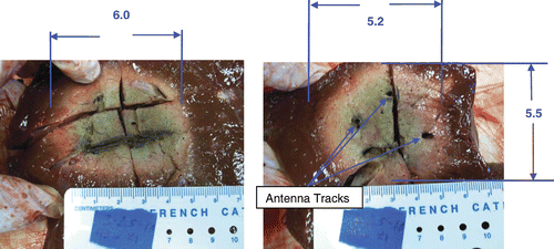
Figure 1. Results for three synchronous, uncooled antennas, 4.2 cm (diameter) × 5.5 cm (length) ablation in ex vivo bovine liver with three antennas at 915 MHz, spaced 1.3 cm apart in triangular array (10 min, 33 W/channel, synchronous phase, no cooling).
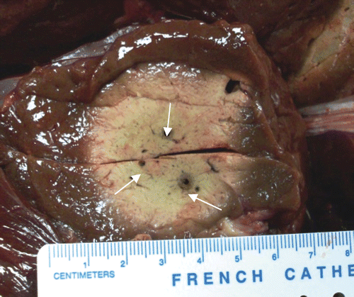
Figure 2. Results from three non-synchronous antennas, 2.5 cm (diameter) × 2.9 cm (diameter) × 6 cm (length) ablation in ex vivo bovine liver with three antennas at 915 MHz, spaced 1.3 cm in triangular array (10 min, 33 W/channel, non-synchronous phase, no cooling).
shows the results of a single cooled antenna, in two different planes of evaluation.
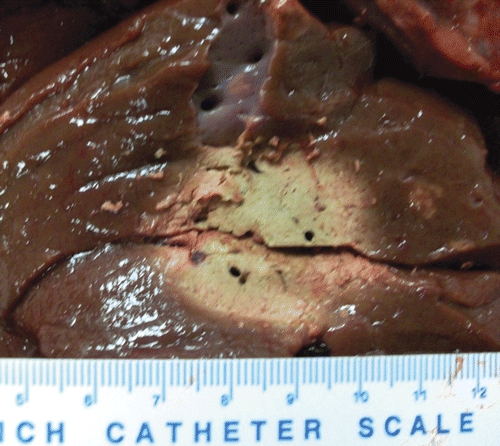
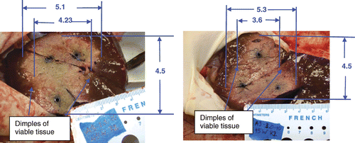
Figure 3. Single cooled antenna results, 2.9 cm (diameter) × 3 cm (diameter) × 6.1 cm (length) ablation in ex vivo bovine liver with 1 antenna at 915 MHz (10 min, 60 W, cooled antenna). A 10 mL/min flow rate was used. The left figure shows the insertion plane (arrows designate the track) and the right figure shows the perpendicular plane (arrow shows insertion).
shows the results in two planes of a pair of antennas operated as an array. Both antennas are synchronous and cooled.
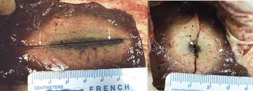
Figure 4. Dual synchronous, cooled antenna results, 4 cm (diameter) × 4.6 cm (diameter) × 5.5 cm (length) ablation in ex vivo bovine liver with two antennas (see white arrows for track indication) at 915 MHz, spaced 1.5 cm apart (10 min, 60 W/channel, synchronous phase, cooled antennas). The left figure shows the insertion plane and the right figure shows the perpendicular plane (see white arrows for antenna locations).
shows the result of three antennas in a triangular array operated as a synchronous array. Two planes are evaluated.
Figure 5. Triple synchronous, cooled antenna results, 5.2 cm (diameter) × 5.5 cm (diameter) × 6 cm (length) ablation in ex vivo bovine liver with three antennas at 915 MHz. (10 min, 45 W/antenna, cooled antennas). The left figure shows the insertion plane and the right figure shows the perpendicular plane. Spacing was 2.5 cm between antennas. With spacing pushed out to 3 cm (not shown) the dimensions of the volume are 5.3 cm (diameter) × 5.1 cm (diameter) × 5.1 cm (length), with some loss of volume when compared to the 2.5 cm spacing runs.
shows the results of three antennas in a triangular array operated as a non-synchronous array. The cross-sectional plane is shown for both 2.5 and 3 cm spaced arrays.
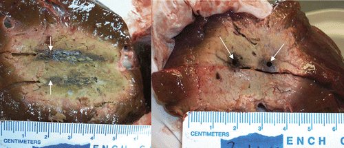
Figure 6. Triple non-synchronous, cooled antenna results. Left: spacing = 2.5 cm. Cross-section of the ablation was 4.2 cm (minimum diameter) × 4.5 cm (diameter) × 5.4 cm (length) (10 min, 45 W/channel, non-synchronous phase, cooled antennas). There are treatment gaps of viable tissue between antennas where the ablation lacks sphericity. Right: spacing = 3 cm. Cross-section of the ablation was 3.6 cm (minimum diameter) × 4.5 cm (diameter) × 5 cm (length) (10 min, 45 W/channel, non-synchronous phase, cooled antennas). The treatment gaps are even larger when the antenna spacing is increased.
A summary of all the runs is presented in . The mode (synchronous or non-synchronous) and spacing between antennas is shown, as well as ablation dimensions. In addition, volume and total energy are calculated. Lastly, efficiency is shown, which is volume/energy. Higher efficiency will be an advantage as one is able to obtain a larger volume over a shorter time frame.
Table I. Transition from hyperthermia to ablation with interstitial MW antennas.
Table II. Summary of the experimental data with synchronous (S) and non-synchronous (NS) denoted. Synchronous runs showed larger volumes and higher efficiency ratios, denoting a larger volume for the same energy input. L1 and L2 are the two diameters, perpendicular to the insertion of the antennas. L3 is the length in the direction of insertion of the array.
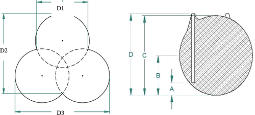
right shows how the ablation shape was analysed. A is apex to antenna tip; B is apex to girth; C is central length; D is apex to shaft peak. Dimensions ‘D1’, ‘D2’, and ‘D3’ ( left) were used the ablation was more triangular, in a plane perpendicular to the insertion path of the antennas. The graphic in shows where measurements were taken if the ablation was more an assemblage of circles, rather than a large, contiguous circle, in cross-section.
Figure 7. Ablation shape scale definition for the plane perpendicular to the insertion axis (left) and parallel to the insertion axis (right).
The results of synchronous and non-synchronous ablations are found in . ‘Apex’ refers to the point that is the central, distal extent of the ablation beyond the antenna ‘tip’, and ‘girth’ refers to the point of the largest diameter along the insertion length when the ablation is cut perpendicular to the shaft insertion, extending through the centre of the array. ‘Shaft peak’ is found where the ablation extends along the shaft of the antenna causing a peak which extends further than the central length of the ablation.
Table III. Detailed comparison between the largest spacing of 2.5 and 3 cm (relating to and ) runs with three antennas in a triangular configuration. The synchronous runs had no D2 measurements since they were more spherical. In addition, the synchronous runs had no D values since the peak was central, not located in the vicinity of the antenna shafts.
Treatment planning results
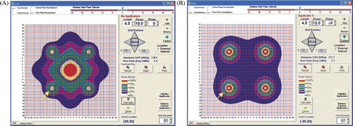
The numerical model results of a three-antenna array are shown for synchronous and non-synchronous run conditions in , respectively.
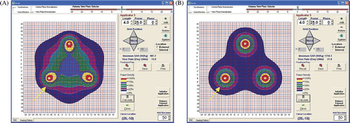
Figure 8. Three antenna simulations: synchronous versus non-synchronous. (A) The predicted SAR pattern with three synchronous antennas (see arrow) spaced 2.2 cm on a side with triangular cross section. (B) The predicted SAR pattern with three non-synchronous antennas (see arrow) spaced 2.2 cm on a side with triangular cross section.
The numerical model results of a four-antenna array are shown for synchronous and non-synchronous run conditions in , respectively.
Figure 9. Four antenna simulations: synchronous versus non-synchronous. (A) The predicted SAR pattern with four synchronous antennas (see arrow) spaced 2.4 cm on a side with square cross-section. (B) The predicted SAR pattern with four non-synchronous antennas (see arrow) spaced 2.4 cm on a side with square cross-section.
Ablation and simulation results
Ablation results in this study were shown for one, two, and three antennas in ex vivo bovine liver. Cooled and non-cooled antennas were compared as well as synchronous and non-synchronous antenna driving relationships. Cooling allowed the power to be increased from 33 W to 45–60 W per antenna for percutaneous applications and helped prevent skin (surface) damage. In and , three antennas were placed in tissue in a triangular array with 33 W/antenna. No antenna cooling was performed. In the coherent or synchronous phased array, the lesion was 4.2 × 5.5 cm. was powered non-synchronously and the results were much smaller: 2.5 × 2.9 cm in diameter and 6 cm long. The volumes were 50.8 and 22.8 cm3, respectively. The phase relationship and constructive interference in the synchronous array resulted in a much larger and more spherical ablation at the same power. Efficiency was 0.9 versus 0.4 for synchronous versus non-synchronous, respectively, (see ).
The performance of a single antenna with cooling (rate of 10 mL/min) and higher power (60 W) is shown in . The ablation was 2.9 × 3 cm in cross section. Obviously cooling did not create a larger lesion but allowed a higher power level which resulted in a larger volume of ablation, confirming what others have reported in the literature.
For two cooled antennas spaced 1.5 cm apart, with a power of 60 W/antenna, the results are shown in . The antennas were powered synchronously for 10 min and showed an ablation of 4 × 4.6 cm in cross section.
shows an array of three antennas powered synchronously at 45 W/antenna at 2.5 cm spacing. The volume was 5.2 × 5.5 × 6 cm creating a volume of 89.8 cm3. shows the same run performed non-synchronously with a volume reduction to 4.2 × 4.5 × 5.4 cm or 53.4 cm3. If the synchronous run was extended to 3 cm spacing, the volume was 72.1 cm3, while the non-synchronous run was 42.4 cm3. This is analysed in and .
also shows the non-spherical volume in the non-synchronous mode, with the results looking more like three circles with a void of untreated tissue between them. The efficiency is calculated as volume/energy and is high in the synchronous cases and low in the non-synchronous cases. shows this comparison clearly. utilises further analysis to show the nuances of ablation shape, especially as spacing becomes large (2.5 or 3 cm), such that the zone is no longer spherical in the non-synchronous case. The synchronous results were all spherical or elliptical, with no zones of non-treatment appearing between antennas.
Simulation results using basic homogeneous numerical modelling are shown for three and four antennas for both synchronous and non-synchronous activation. For three antennas spaced 2.2 cm on a side at equal power, synchronous and non-synchronous results are shown in , respectively. In the non-synchronous case in , the antennas have no phase relationship or central constructive interference, as if the antennas were turned on rapidly at separate times. As a result, there is little central power deposition and the 25% and 50% isoSAR contours are only found in the vicinity of the antennas. Contrast these results to the synchronous case in which shows a large central region of 25% and 50% isoSAR, with values approaching 75% isoSAR. This implies that in , the central region would heat immediately, whereas in , since less than 25% SAR is found centrally it would rely on thermal conduction to fill in all zones not in the immediate vicinity of the antenna.
For four antennas, the synchronous and non-synchronous numerical model results are shown in , respectively. Antennas are spaced in a square array with 2.4 cm on a side. As seen in the previous two figures, the non-synchronous case shows no central heating whereas the synchronous results show the primary heating focused centrally in the array, avoiding overheating around the antennas themselves. Note the lack of phase addition that would cause constructive interference in the central area in . The advantages of synchronous power to an array of three or four antennas are clearly seen in and .
Treatment planning
MW interstitial treatment planning is currently used on a limited basis with hyperthermia in combination with brachytherapy Citation[92]. For thermal therapy, planning of access routes, number and locations of zones for treatment and any monitoring points need to be laid out carefully in advance Citation[54]. In both hyperthermia and ablation, treatment planning is still in its infancy, although it has been commercially available for hyperthermia since 1984 (BSD 500 model).
In a published tumour study, regular prism and regular polyhedron models for preoperative planning were created for liver tumour ablation to minimise the number of ablation spheres, optimise the overlapping mode, and determine electrode placement. For tumours 5.7–6.5 cm, the treatment target was 6.7–7.5 cm, requiring 12 ablation spheres (assumes 5 cm ablation sphere per antenna). In spite of careful preplanning the study still missed the tumour as the electrode tip deviated from the predetermined position and there was a 24% recurrence rate Citation[93]. In ablation thermal therapy for cancer, MW antennas are usually inserted parallel to one another, with the tips in the same plane Citation[37]. If one deviates from either of these conditions (parallel insertion and tip alignment), treatment planning is recommended to help predict the consequences (especially since the presence of cold spots could lead to recurrence) Citation[17]. The more elliptical shape of some MW ablations may also be an advantage for larger tumours.
Discussion
High frequency MW: historical origin
Experiments performed at MIT during World War II indicated that the absorption of MW at 2450 MHz in water was 7000 times that of short wave diathermy at 27 MHz (popular in that era). Thus the FCC reserved this frequency for physical medicine due to its therapeutic potential of its energy penetration in tissue and consequently this frequency was adopted for microwave ovens Citation[6]. The current FCC regulations also allow 915 MHz for medical applications.
Microwave heating of tissue
The dominant mode of propagation of microwave heating using antennas is radiative and the tissue absorption is primarily due to dielectric losses Citation[94]. The EM properties of tissue are governed by structural components including cellular membranes, proteins and water content. MW antennas induce rotation of water molecules due to dipole action, causing them to oscillate at the frequency of the electromagnetic field (915 or 2450 MHz). Molecular motion is restricted by frictional forces that convert the rotational energy into heat and each atomic dipole becomes a heating source. Thus when MW power is turned on, the polar molecules in tissue begin to rotate and heat immediately and simultaneously at both near and far locations, with the electric field propagating outward to a radius of about 10–20 mm Citation[37]. This rapid heating results in coagulation necrosis of tissue when temperatures exceed about 55°C. The power distribution around a MW antenna together with heat conduction determines the temperature and resulting damage to the treated tissue Citation[95].
Validation of MW performance
As in other interstitial technologies used for ablation (laser, RF, and ultrasound), MW sources are of comparable size, easily cooled, and can be used singly or in arrays Citation[7], Citation[10], Citation[57], Citation[67], Citation[68], Citation[77], Citation[96], during surgical, laparoscopic and percutaneous procedures Citation[75], Citation[83].
Microwaves have been reported to have several advantages over other technologies: (1) deep penetration Citation[53], Citation[77], Citation[79], Citation[84]; (2) no direct electrical contact required (thus all metallic surfaces may be coated with non-stick coatings) Citation[54]; (3) rapid heating with shorter ablation times Citation[77], Citation[84], Citation[97]; (4) no power delivery limitations due to tissue charring Citation[54], Citation[75], Citation[98]; (5) allows for deeper penetration due to an increase in transparency to microwaves even with near field tissue desiccation Citation[90]; (6) higher temperatures Citation[54], Citation[97], Citation[99]; (7) coagulation of vessels Citation[53], Citation[73], Citation[75], Citation[78], Citation[98] and an improved convection profile Citation[78], Citation[84], Citation[99]; (8) heats large volumes Citation[53], Citation[56], Citation[57], Citation[73], Citation[75], Citation[76], Citation[84], Citation[87], Citation[96], Citation[98], Citation[99], and (9) provides advantages due to the phase relationships between antennas (allowing constructive or destructive interference) Citation[16–18], Citation[35–38]. MW ablation has clinical relevance in providing an alternative to surgical resection Citation[82], Citation[98], Citation[100], with reliable local control Citation[54], Citation[73], Citation[76], Citation[85], Citation[96], and high rates of complete ablation Citation[87], Citation[98], Citation[101].
From a more technical standpoint, further advantages include the customisation of MW interstitial antennas and arrays such that the power distribution in both axial and radial directions may be altered by changing antenna designs Citation[9]. This was shown with several different antenna types, showing how differences in tip, centre, and insertion point values of power deposited, as well as array behaviour is adjustable due to the phase relationships among antennas in an array Citation[18], Citation[90]. Depending on the antenna design, the heating at the insertion point may be affected, an important consideration in percutaneous procedures Citation[9], Citation[18].
In the work by Hines-Peralta et al. Citation[90] with high power MW antennas, in vivo coagulation diameters exceeded ex vivo results for the same power and time values, in cases where treatment time was 8 min or less. This is most likely due to the well hydrated in vivo liver, with high water content because of tissue rich in blood that replenishes during ablation Citation[90]. Tumours also have high water content which could prove to be another advantage with MW treatment ablation because of tumour tissue absorbing more energy due to higher electrical conductivity. The study also found that the ablation volumes were more spherical in vivo than ex vivo, most likely due to the effects of perfusion in the highly vascular liver. This will provide a good match to tumours which are also spherical in most cases and may help target the tumour and not the less hydrated, neighbouring tissue such as cirrhotic liver, fat and bone Citation[90].
Phased array overview and performance
In antenna arrays, whether with two to four or more antennas, maximum constructive or destructive interference is achieved for monopoles or dipoles when each antenna is simultaneously active and synchronised in phase (phase synchronous). When the phases radiated from each antenna are the same they are phase coherent. This would be the case if all were fed from a power splitter and had equal length cables. Phase synchronous and coherent arrays have two or more antennas at the same frequency and are controlled with a specific relative phase difference between sources. Phase coherent arrays have two or more sources of EM radiation at the same frequency and are maintained with the same phase relationship between these antennas.
Non-synchronous phase is the condition when the antennas are not simultaneously active or when they have separate generators that are simultaneous but not identically controlled in their frequency and phase output, and thus do not have constructive interference. It would be as if time multiplexing was used and only one antenna was on at a time, such that relative phase relationships between antennas would be uncorrelated.
When phased array principles are used in a cylindrical array to provide a convergent radiated wave, it results in a centralised focal region of energy. The radiation from all the EM sources in this configuration provides approximately the same phase and electric field (E-field) polarisation. This process enhances the power deposition in the focal region of the array and the region is surrounded by a cylindrical area where differing phases create interference which decreases the power deposition near the antenna. Some degree of selective power targeting at depth in tissues is possible because of this behaviour and it also allows for deep targets in human cancer treatment.
Our single cooled antenna results show a cross-section of 2.9 × 3 cm at 60 W and 10 min. Dual antennas increased the cross-section to 4 × 4.6 cm at 60 W per antenna and 10 min. Laeske et al. Citation[77] compared single versus dual antennas in in vivo kidney and found 3.2 × 3.9 cm for a single and 3.9 × 5.8 for a pair. All antennas were at 90 W per channel for 12 min. Both sets of results show good scaling from single to dual antennas and may help in the selection of an antenna set-up, depending on target size.
Performance differences were seen in this paper's results when synchronous phase arrays are compared to non-synchronous phase in an ex vivo model. For an array of three antennas at 33 W/antenna, the synchronous array produced 4.2 cm (diameter), whereas the non-synchronous produced 2.7 cm diameter. Cooled antennas at 45 W/channel were also tested. The synchronous array produced 5.2 × 5.5 cm cross-section (volume 89.8 cm3) and non-synchronous produced 4.2 × 4.5 cm (volume = 53.4 cm3). The antennas and power/cooling were identical, only the phase relationship was different. In addition, at spacings of 2.5 and 3 cm for a triple antenna array, non-synchronous arrays showed zones of non-treatment between antennas, whereas the synchronous antennas filled in these zones as a contiguous cross-sectional region. This was verified in the simulation results for three antennas in . Four antenna results also showed an advantage with central power deposition when a synchronous array was used (see ). Wright et al. Citation[102] compared activation of an antenna array with three antennas in a triangular array at 40 W per antenna and 10 min in in vivo porcine liver. The three antennas were activated either sequentially (no phase relationship) or synchronously. The synchronous results were 43.1 cm3 versus 14.6 cm3 for sequential operation.
In our study there are advantages with using synchronous power. (1) Ablations performed with synchronous power are more spherical and contiguous, without gaps in the cross-section, than ablations performed with non-synchronous power using the same type of antenna at larger spacing, and (2) synchronous ablations have larger diameters than the corresponding non-synchronous configurations and also had higher efficiency.
Others have found advantages with synchronous systems which have a phase relationship among the antennas of the array. The heating at the centre of an array may be enhanced as N if the array is non-synchronous, but more advantageously as N2 (where N = number of antennas) when the antennas are synchronous Citation[103].
Changing and steering phase amongst stationary antennas is simply done by changing the phase of one or more antennas, but must start with a synchronous system. This has been utilised both in vivo and in clinical treatments: (1) in vivo work in animals and patients showed that temperature distributions could be changed by shifting phase amongst the array of microwave antennas Citation[104], (2) patient studies showed advantages of changing phase to better heat tumours Citation[10], (3) heating at depth was optimised using temperature steering by adjusting the phase between antennas, which may open up new organs for treatment, such as the prostate Citation[105], (4) heating volume was increased with changing phase among antennas Citation[106] and phase shifting was able to shift heating out to the periphery of a tumour Citation[107], (5) phase shifting demonstrated both uniform and intentionally non-uniform heating patterns by phasing an array of microwave antennas, including peripheral heating patterns around the outside of the array Citation[108], (6) synchronous antennas allowed the movement of antennas further apart while still getting sufficient heating in the array centre Citation[109], and (7) based on any of a number of thermal therapy feedback controls, the system altered phase and antenna power to move or change the power deposition field with otherwise stationary applicators Citation[110].
Recent theoretical and laboratory work suggests using a variety of antenna designs (each having a different SAR pattern) to customise the ablation shape according to the tumour target shape. Further, this study also used three antennas in a plane, triangular, or in a T-pattern to produce unique ablation shapes Citation[111]. This type of antenna selection, spacing, and placement will need an interactive treatment planning system to help optimise the array configuration relative to the target.
Frequency and tissue considerations
When considering using phased arrays, the choice of frequency is important in MW heating of tissue. In high water content tissue such as muscle and liver, the effective wavelength at 915 MHz is 4.4 cm and at 2450 MHz is 1.8 cm. MW planewave penetration (1/e where power reduces to 13.5% of the surface) at 915 MHz is 3 cm and at 2450 MHz is 1.7 cm Citation[112]. If the standing wave pattern of overlapping fields results in the distance between phase maxima and minima of approximately a quarter-wavelength in the tissue, this would mean the distance between the energy peak and the adjacent energy null would be 11 mm for 915 MHz and 4.4 mm for 2450 MHz. This leads to less favourable phased array applications at 2450 MHz, but accommodates synchronous arrays at 915 MHz that are spaced less than 25 mm. Thus, a synchronous phased array, due to wavelength advantages favours 915 MHz because of a more uniform SAR Citation[37], Citation[38].
Antennas in catheters or antennas with dielectric coatings, as used in the clinic and operating room, will change the tip section lengths to remain resonant in tissue. Antennas in catheters at frequencies of 433 and 915 MHz had tip sections of 6.8 and 3.5 cm, respectively, as calculated by Trembly Citation[37], Citation[38]. While the 433 MHz antenna array heated longer tumours most effectively, the antennas driven at 915 MHz were most effective at heating medium-length tumours, especially tumours with high blood flow Citation[39]. Some applicators have been customised for oesophageal Citation[113], prostate Citation[114], and rectal/anal sites.
The dielectric properties at 915 MHz that change with temperature are likely determined by the combined effects of tissue water and small proteins. Changes in the dielectric properties due to coagulation are expected as elevated temperatures lead to structural and conformational changes in tissue Citation[73]. Electrical conductivity increases by a factor of 1.5 to 2 as tissue temperatures approach 60°–70°C although permittivity increases only by 5%–10%. An important aspect though is that these changes were irreversible when temperatures exceeded 50°C, with a greater permanent increase at temperatures greater than 62°C. This coincides with irreversible changes with elevated temperatures found at lower frequencies Citation[115].
Cooling influence on clinical results
A large 433 MHz antenna with water cooling used more than 25 years ago was developed for the treatment of prostate cancer. A control system regulating the power output of the radiator avoided damage to the tissue around the prostate, especially the rectal mucosa and the tissue between rectum and prostate. About 60 experiments with male dogs proved that local heating of the prostate was possible without any damage in the surrounding tissue if cooling was used Citation[59].
The treatment of recurrent prostate cancer with MW thermal ablation was clinically evaluated and reported by Trachtenberg and Sherar Citation[61], Citation[62]. Cooled antennas with a sharp cutting tip integrated for percutaneous insertion and a dielectric gap were used Citation[63]. Later, the same group reported efforts using a multichannel MW system (BSD-500) and a phase coherent array (BSD Medical). The initial clinical results were reported on 41 patients showing feasibility of this treatment method Citation[61], Citation[62].
Another system (Prostathermer) was designed to deliver hyperthermic treatment to the prostate gland and was used to treat six patients with BPH and urinary retention. The system had built-in water cooling and temperature probes. Six patients received 47 hyperthermic sessions of 1–2 treatments/week. Temperatures achieved were 39.4° to 45.2°C, carried out for 60 min in each session Citation[116].
In this study, cooling allowed for greater power to be applied to an antenna and array resulting in larger ablations. The results of the experimental work should be regarded as additional data that support other cited data reported in the literature.
Thermal dose requirements
Initial thermal dose equivalence at moderate temperatures was described by Sapareto and Dewey Citation[117] as a target dose of 43°C for 60 min, equivalent to 44°C for 30 min, or 45°C for 15 min. In their survival-fraction work with Chinese hamster ovary (CHO) cells, 41°C was the minimum and 46.5°C was the maximum tested. Later, as ablation became more prevalent, cytotoxic temperature goals were defined in the range 50°–54°C for 4–6 min Citation[118].
In thermal treatment, tissue is necrosed due to the thermal history with typical times of seconds to minutes and peak temperatures at 50°–70°C or greater. He and Bischof Citation[119] tested human renal carcinoma cells at even higher temperatures. The platform with the cells was rapidly heated to a plateau temperature, remained constant for a given time period, and then cooled rapidly. It was found that cell viability drops monotonically with increasing hold time for all peak temperatures. Thus, at 60°C, the viability of tumour cells was less than 20% after 1 min of treatment. At 70°C, nearly all cells were killed with no hold time required. Understanding cell injury kinetics will help to drive treatment protocols, especially since very high temperatures could be found in any ablation treatments, be it with RF, laser, or MW sources Citation[91]. There is also variation in treatment outcomes in different organs and one study summarised the heat sensitivity of various cell and organ types, with kidney showing the highest critical dosimetry and breast adenocarcinoma the lowest required dosimetry Citation[91].
Table IV. Steps in the transition from hyperthermia (HT) to thermal ablation (TA).
Image guidance and monitoring
Current ablation technology incorporates image guidance into most procedures. Surgeons performing ablations in open surgery frequently use ultrasound for depth information and in laparoscopic cases will use laparoscopic ultrasound. Interventional radiologists frequently use CT and/or ultrasound for tumour localisation and antenna placement. Thus, technology is moving toward more spatially accurate and controllable heating systems combined with image-guidance and treatment verification Citation[72].
Sato et al. Citation[120] describe an advanced system located in their clinic with real-time open Magnetic Resonance (MR) imaging Citation[121], performing the following steps: (1) MR volume data acquisition of target, (2) treatment planning using ellipsoidal ablation zones overlapped to cover the entire target region, (3) MW needles (which have coils for magnetic gradient detection) feedback information to the MR scanner to track each MW antenna position with 6 degrees of freedom, (4) visualisation is made possible with an MR compatible endoscope for visual guidance in thoracic cavity, (5) temperature data is acquired with the MR scanner of the target in 3D for monitoring and assessment; and (6) the computer keeps track of the order and location of ablations during the total treatment time Citation[120], Citation[121].
Another study used preoperative patient images to generate anatomic structures. Then antenna trajectories were superimposed on the 3D scene and necrosis fields were superimposed (predictions confirmed by CT previously in other studies). The surgeon iteratively adjusted treatment zones (trajectories and locations) to best optimise the treatment. Tissue necrosis was predicted during planning using the bioheat equation, tissue properties, blood flow as function of temperature, and the Arrhenius equation to infer the boundary of the thermal necrosis field, incorporating temperature history over the treatment Citation[121]. Further additions to the model would include water content changes, latent heat loss, water vaporisation and diffusion, and vapour condensation Citation[58].
Future directions
Larger targets: As raw generator power increases, combined with higher power antennas and more array channels, MW thermal ablation is expected to make further in-roads into larger ablations that will treat 7-cm tumours or larger.
Specialised antennas: New tip-heating antennas have been designed that selectively heat small targets that are presently treated with small RF applicators.
Navigation with co-registration: Technology exists to co-register a treatment target with a treatment device but has not been incorporated into systems that utilise ablation.
New malignant organ sites: Following liver ablation, new tumour sites will be targeted with MW, including lung, breast, prostate and bone metastases.
New non-malignant organ sites: There are other non-cancerous sites favourable for MW ablation with custom applicators that will offer the patient an alternative to surgery, with sites including the prostate to treat benign prostatic hyperplasia as well as uterine fibroids.
Conclusions
This paper shows the transition and evolution from hyperthermia to ablation with interstitial techniques and sources. By examining the early history, it is clearly shown that direct MW antenna insertion into tissue, high temperature heating, antenna cooling, synchronous and non-synchronous array operation, as well as treatment planning have been practiced for 20–30 years. Although many similarities are found in the technology, the ablation procedures now incorporate real-time image guidance but commonly lack the use of extensive treatment planning and temperature monitoring typical of hyperthermia treatments. Future systems are expected to incorporate advanced features in 3D that may include: treatment planning, image-guided placement, system knowledge of actual antenna location and trajectory along with target localisation, real-time thermography or necrosis boundary imaging, as well as flexibility in antenna locations and power deposition control for conformability with the target. Better models are needed to predict coagulative volumes with MW which will utilise tissue dielectric and thermal properties (tumour versus normal) as a function of temperature, as well as perfusion and water content changes.
Declaration of interest: The authors report no conflicts of interest except that Turner and Hamilton are employees of BSD Medical Corporation that develops devices reported in the article. The authors alone are responsible for the content and writing of the paper.
Related Research Data
References
- Taylor LS. Electromagnetic syringe. IEEE Trans Biomed Eng 1978; 25: 303–304
- Taylor L. Implantable radiators for cancer therapy by microwave hyperthermia. Proc IEEE 1980; 68: 142–149
- Bigu-del-Blanco J, Romero-Sierra C. The design of a monopole radiator to investigate the effect of microwave radiation in biological systems. J Bioeng 1977; 1: 1181–1184
- Strohbehn JW, Bowers ED, Walsh JE, Douple EB. An invasive microwave antenna for locally induced hyperthermia for cancer therapy. J Microw Power 1979; 14: 339–350
- Douple EB, Strohbehn JW, Bowers ED, Walsh JE. Cancer therapy with localized hyperthermia using an invasive microwave system. J Microw Power 1979; 14: 181–186
- Guy AW, Lehmann JF, Stonebridge JB. Therapeutic applications of electromagnetic power. Proc IEEE 1974; 62: 55–75
- Sneed PK, Stauffer PR, McDermott MW, Diederich CJ, Lamborn KR, Prados MD, Chang S, Weaver KA, Spry L, Malec MK, et al. Survival benefit of hyperthermia in a prospective randomized trial of brachytherapy boost +/− hyperthermia for glioblastoma multiforme. Int J Radiat Oncol Biol Phys 1998; 40: 287–295
- Sapozink M, Boyd S, Astrahan M, Jozsef G, Petrovich Z. Transurethral hyperthermia for benign prostatic hyperplasia: Preliminary clinical results. J Urology 1990; 143: 944–950
- Gross EJ, Cetas TC, Stauffer PR, Liu RL, Lumori ML. Experimental assessment of phased-array heating of neck tumours. Int J Hyperthermia 1990; 6: 453–474
- Ryan TP, Trembly BS, Roberts DW, Strohbehn JW, Coughlin CT, Hoopes PJ. Brain hyperthermia: I. Interstitial microwave antenna array techniques–The Dartmouth experience. Int J Radiat Oncol Biol Phys 1994; 29: 1065–1078
- Coughlin CT, Wong TZ, Ryan TP, Jones EL, Crichlow RW, Spiegel PK, Jeffery R. Interstitial microwave-induced hyperthermia and iridium brachytherapy for the treatment of obstructing biliary carcinomas. Int J Hyperthermia 1992; 8: 157–171
- Sherar MD, Trachtenberg J, Davidson SR, Gertner MR. Interstitial microwave thermal therapy and its application to the treatment of recurrent prostate cancer. Int J Hyperthermia 2004; 20: 757–768
- Seegenschmiedt MH, Martus P, Fietkau R, Iro H, Brady LW, Sauer R. Multivariate analysis of prognostic parameters using interstitial thermoradiotherapy (IHT-IRT): Tumor and treatment variables predict outcome. Int J Radiat Oncol Biol Phys 1994; 30: 1049–1063
- Seegenschmiedt MH, Karlsson UL, Black P, Brady LW. Thermoradiotherapy for brain tumors. Three cases of recurrent malignant astrocytoma and review of clinical experience. Am J Clin Oncol 1995; 18: 510–518
- Overgaard J, Gonzalez Gonzalez D, Hulshof MC, Arcangeli G, Dahl O, Mella O, Bentzen SM. Randomised trial of hyperthermia as adjuvant to radiotherapy for recurrent or metastatic malignant melanoma: European Society for Hyperthermic Oncology. Lancet 1995; 345: 540–543
- Jones EL, Oleson JR, Prosnitz LR, Samulski TV, Vujaskovic Z, Yu D, Sanders LL, Dewhirst MW. Randomized trial of hyperthermia and radiation for superficial tumors. J Clin Oncol 2005; 23: 3079–3085
- Emami B, Scott C, Perez CA, Asbell S, Swift P, Grigsby P, Montesano A, Rubin P, Curran W, Delrowe J, et al. Phase III study of interstitial thermoradiotherapy compared with interstitial radiotherapy alone in the treatment of recurrent or persistent human tumors. A prospectively controlled randomized study by the Radiation Therapy Group. Int J Radiat Oncol Biol Phys 1996; 15: 1097–1104
- Ryan TP, Mechling JA, Strohbehn JW. Absorbed power deposition for various insertion depths for 915 MHz interstitial dipole antenna arrays: Experiment versus theory. Int J Radiat Oncol Biol Phys 1990; 19: 377–387
- Ryan TP, Hoopes PJ, Taylor JH, Strohbehn JW, Roberts DW, Douple EB, Coughlin CT. Experimental brain hyperthermia: Techniques for heat delivery and thermometry. Int J Radiat Oncol Biol Phys 1991; 20: 739–750
- Ryan TP. Comparison of six microwave antennas for hyperthermia treatment of cancer: SAR results for single antennas and arrays. Int J Radiat Oncol Biol Phys 1991; 21: 403–413
- Kanaoka Y, Yoshida C, Fukuda T, Kajitani K, Ishiko O. Transcervical microwave myolysis for uterine myomas assisted by transvaginal ultrasonic guidance. J Obstet Gynaecol Res 2009; 35: 145–151
- Liang P, Wang Y, Zhang D, Yu X, Gao Y, Ni X. Ultrasound guided percutaneous microwave ablation for small renal cancer: Initial experience. J Urol 2008; 180: 844–848
- Carrafiello G, Laganà D, Mangini M, Fontana F, Dionigi G, Boni L, Rovera F, Cuffari S, Fugazzola C. Microwave tumors ablation: Principles, clinical applications and review of preliminary experiences. Int J Surg 2008; 6: S65–69
- Grieco CA, Simon CJ, Mayo-Smith WW, Dipetrillo TA, Ready NE, Dupuy DE. Image-guided percutaneous thermal ablation for the palliative treatment of chest wall masses. Am J Clin Oncol 2007; 30: 361–367
- Laing P, Wang Y. Microwave ablation of hepatocellular carcinoma. Oncology 2007; 72: 124–131
- Liang P, Wang Y, Yu X, Dong B. Malignant liver tumors: Treatment with percutaneous microwave ablation–Complications among a cohort of 1136 patients. Radiology 2009; 251: 933–940
- Carrafiello G, Laganà D, Mangini M, Fontana F, Dionigi G, Boni L, Rovera F, Cuffari S, Fugazzola C. Microwave tumors ablation: Principles, clinical applications and review of preliminary experiences. Int J Surg 2008; 6: S65–69
- Chen JC, Moriarty JA, Derbyshire JA, Peters RD, Trachenberg J, Bell SD, Doyle J, Arrelano R, Wright GA, Henkleman RM, et al. Prostate cancer: MR imaging and thermometry during microwave thermal ablation-initial experience. Radiology 2000; 214: 290–297
- Short G, Turner P. Physical hyperthermia and cancer therapy. Proc IEEE 1980; 68: 133–142
- Turner P. Invasive hyperthermia apparatus and method. US Patent No. 4,448,198, 1984.
- Waterman FM, Nerlinger RE. The effect of coupling materials on specific absorption rate distributions at 915 MHz. Med Phys 1986; 13: 391–395
- Cheung AY, Neyzari A. Deep local hyperthermia for cancer therapy: External electromagnetic and ultrasound techniques. Cancer Res 1984; 44: S4736–4744
- Hoh LL, Waterman FM. Use of manganin-constantan thermocouples in thermometry units designed for copper-constantan thermocouples. Int J Hyperthermia 1995; 11: 131–138
- Turner P. Interstitial EM application/temperature probes. Proceedings of the Eighth Annual Conference of the IEEE Engineering in Medicine and Biology Society, 1986, Vol. 3: 1454–1457.
- Turner P. Proceedings of the Eighth Annual Conference of the IEEE Engineering in Medicine and Biology Society, 86CH2368-9; 1986;3:1454–1457.
- Turner P. Interstitial equal-phase arrays for EM hyperthermia. IEEE Trans Microw Theory Tech 1986; 34: 572–578
- Trembly BS, Ryan TP, Strohbehn JW. Physics of microwave hyperthermia. Hyperthermia and oncology, volume 3: Interstitial hyperthermia: Physics, biology and clinical aspects, M Urano, E Douple. VSP Press, New York 1991; 11–98
- Trembly BS. The effects of driving frequency and antenna length on power deposition within a microwave antenna array used for hyperthermia. IEEE Trans Biomed Eng 1985; 32: 152–157
- Mechling JA, Strohbehn JW, France LJ. A theoretical evaluation of the performance of the Dartmouth IMAAH system to heat cylindrical and ellipsoidal tumour models. Int J Hyperthermia 1991; 7: 465–483
- Kaye JD, Smith AD, Badlani GH, Lee BR, Ost MC. High-energy transurethral thermotherapy with CoreTherm approaches transurethral prostate resection in outcome efficacy: A meta-analysis. J Endourol 2008; 22: 713–718
- Djavan B, Larson TR, Blute ML, Marberger M. Transurethral microwave thermotherapy: What role should it play versus medical management in the treatment of benign prostatic hyperplasia?. Urology 1998; 52: 935–947
- Tabuse Y, Tabuse K, Mori K, Nagai Y, Kobayashi Y, Egawa H, Noguchi H, Yamaue H, Katsumi M, Nagasaki Y. Percutaneous microwave tissue coagulation in liver biopsy: Experimental and clinical studies. Nippon Geka Hokan 1986; 55: 381–392
- Yamashita Y, Sakai T, Maekawa T, Watanabe K, Iwasaki A, Shirakusa T. Thorascopic transdiaphragmatic microwave coagulation therapy for a liver tumor. Surg Endoscopy 1998; 12: 1254–1258
- Murakami R, Yoshimatsu S, Yamashita Y, Matsukawa T, Takahashi M, Sagara K. Treatment of hepatocellular carcinoma: Value of percutaneous microwave coagulation. Am J Radiol 1995; 164: 1159–1164
- Rhim H. Review of Asian experience of thermal ablation techniques and clinical practices. Int J Hyperthermia 2004; 20: 699–712
- Lu Y, Nan Q, Li L, Liu Y. Numerical study on thermal field of microwave ablation with water-cooled antenna. Int J Hyperthermia 2009; 25: 108–115
- King RP, Trembly BS, Strohbehn JW. The electromagnetic field of an insulated antenna in a conducting or dielectric medium. IEEE Trans Biomed Eng 1983; 31: 574–583
- Astrahan M, Luxton G, Petrovich Z. Thermometry characteristics of BSD interstitial hyperthermia applicator. Endocurie Hyperthermia Oncol 1987; 3: 153–160
- Sathiaseelan V, Leytbovich L, Ememi B, Stauffer P, Straube W. Characteristics of improved microwave interstitial antennas for local hyperthermia. Int J Radiat Oncol Biol Phys 1991; 20: 531–539
- Satoh T, Stauffer PR, Fike JR. Thermal distribution studies of helical coil microwave for interstitial hyperthermia. Int J Radiat Oncol Biol Phys 1988; 15: 1209–1218
- Satoh T, Seilman TM, Stauffer PR, Sneed PK, Fike JR. Interstitial Helical coil microwave antenna for experimental brain hyperthermia. Neurosurgery 1988; 23: 564–569
- Reeves JW, Birch MJ, Hand JW. Comparison of simulated and experimental results from helical antennas within a muscle equivalent phantom. Phys Med Biol 2008; 53: 3057–3070
- Kuang M, Lu MD, Xie XY, Xu XY, Mo HX, Liu GJ, Xu ZF, Zheng YL, Liang JY. Liver cancer: Increased microwave delivery to ablation zone with cooled-shaft antenna: Experimental and clinical studies. Radiology 2007; 242: 914–924
- Ryan TP, Clegg P. Novel microwave applicators for thermal therapy, ablation, and hemostasis. Thermal treatment of tissue: Energy delivery and assessment V, TP Ryan. SPIE Press. 2009; 7181: 1–15
- Pisa S, Cavagnaro M, Bernardi P, Lin JC. A 915-MHz antenna for microwave thermal ablation treatment: Physical design, computer modeling and experimental measurement. IEEE Trans Biomed Eng 2001; 48: 599–601
- Yu Z, Liu W, Fan L, Shao J, Huang Y, Si X. The efficacy and safety of percutaneous microwave coagulation by a new microwave delivery system in large hepatocellular carcinomas: Four case studies. Int J Hyperthermia 2009; 25: 392–398
- Simon CJ, Dupuy DE, Iannitti DA, Lu DS, Yu NC, Aswad BI, Busuttil RW, Lassman C. Intraoperative triple antenna hepatic microwave ablation. Am J Roentgen 2006; 187: 333–340
- Bertram JM, Yang D, Converse MC, Webster JG, Mahvi DM. A review of coaxial-based interstitial antennas for hepatic microwave ablation. Crit Rev Biomed Eng 2006; 34: 187–213
- Scheiblich J, Petrowicz O. Radiofrequency-induced hyperthermia in the prostate. J Microw Power 1982; 17: 203–209
- Leib Z, Rothem A, Lev A, Servadio C. Histopathological observations in the canine prostate treated by local microwave hyperthermia. Prostate 1986; 8: 93–102
- Sherar MD, Trachtenberg J, Davidson SR, Gertner MR. Interstitial microwave thermal therapy and its application to the treatment of recurrent prostate cancer. Int J Hyperthermia 2004; 20: 757–868
- Sherar MD, Trachtenberg J, Davidson SR, McCann C, Yue CK, Haider MA, Gertner MR. Interstitial microwave thermal therapy for prostate cancer. J Endourology 2003; 8: 617–625
- Tierney M, diMonda R. Organ separation for thermal therapy. US Patent No. 5,733,316, 1998.
- Eppert V, Trembly BS, Richter HJ. Air cooling for an interstitial microwave hyperthermia antenna: Theory and experiment. IEEE Trans Biomed Eng 1991; 38: 450–460
- Trembly BS, Douple EB, Hoopes PJ. The effect of air cooling on the radial temperature distribution of a single microwave hyperthermia antenna in vivo. Int J Hyperthermia 1991; 7: 343–354
- Johnson CC, Guy AW. Nonionizing electromagnetic wave effects in biological materials and systems. Proc IEEE 1972; 60: 692–718
- Wong TZ, Strohbehn JW, Jones KM, Mechling JA, Trembly BS. SAR patterns from an interstitial microwave antenna-array hyperthermia system. IEEE Trans Microw Theory Tech 1986; 34: 560–567
- Jones KM, Mechling JA, Strohbehn JW, Trembly BS. Theoretical and experimental SAR distributions for interstitial dipole antenna arrays used in hyperthermia. IEEE Trans Microwave Theory Tech 1989; 37: 1200–1209
- Waterman FM, Nerlinger RE. The effect of coupling materials on specific absorption rate distributions at 915 MHz. Med Phys 1986; 13: 391–395
- Chou CK. Evaluation of microwave hyperthermia applicators. Bioelectromagnetics 1992; 13: 581–597
- Diederich CJ, Stauffer PR. Pre-clinical evaluation of a microwave planar array applicator for superficial hyperthermia. Int J Hyperthermia 1993; 9: 227–246
- Diederich CJ. Thermal ablation and high-temperature thermal therapy: Overview of technology and clinical implementation. Int J Hyperthermia 2005; 21: 745–753
- Garrean S, Hering J, Saeid A, Hoopes PJ, Helton WS, Ryan TP, Espat NJ. Ultrasound monitoring of a novel microwave ablation (MWA) device in porcine liver: Lessons learned and phenomena observed on ablative effects near major hepatic vessels. J Gastorintest Surg 2009; 13: 334–340
- Strickland AD, Clegg PJ, Cronin NJ, Swift B, Festing M, West KP, Robertson GS, Lloyd DM. Experimental study of large-volume microwave ablation in the liver. Br J Surg 2002; 89: 1003–1007
- Awad ME, Devgan L, Kamel IR, Torbensen M, Choti MA. Microwave ablation in a hepatic porcine model: Correlation of CT and histopathologic findings. HPB 2007; 9: 357–362
- Hope WW, Schmelzer TM, Newcomb WL, Heath JJ, Lincourt AE, Norton HJ, Heniford BT, Iannitti DA. Guidelines for power and time variables for microwave ablation in a porcine liver. J Gastrointest Surg 2008; 12: 463–467
- Laeseke PF, Lee FT, Jr, Sampson LA, van der Weide DW, Brace CL. Microwave ablation versus radiofrequency ablation in the kidney: High-power triaxial antennas create larger ablation zones than similarly sized internally cooled electrodes. J Vasc Interv Radiol 2009; 20: 1224–1229
- Bhardwaj N, Strickland AD, Ahmad F, Atanesyan L, West K, Lloyd DM. A comparative histological evaluation of the ablations produced by microwave, cryotherapy and radiofrequency in the liver. Pathology 2009; 41: 168–172
- Brace CL, Hinshaw JL, Laeseke PF, Sampson LA, Lee FT, Jr. Pulmonary thermal ablation: Comparison of radiofrequency and microwave devices by using gross pathologic and CT findings in a swine model. Radiology 2009; 251: 705–711
- Gravante G, Ong SL, Metcalfe MS, Strickland A, Dennison AR, Lloyd DM. Hepatic microwave ablation: A review of the histological changes following thermal damage. Liver Int 2008; 28: 911–921
- Martin RC, Scoggins CR, McMasters KM. Microwave hepatic ablation: Initial experience of safety and efficacy. J Surg Oncol 2007; 96: 481–486
- Wang ZL, Liang P, Dong BW, Yu XL, Yu de J. Prognostic factors and recurrence of small hepatocellular carcinoma after hepatic resection or microwave ablation: A retrospective study. J Gastrointest Surg 2008; 2: 327–337
- Jagad RB, Koshariya M, Kawamoto J, Papastratis P, Kefalourous H, Patris V, Porfiris T, Gevrielidis P, Tzouma C, Lygidakis NJ. Laparoscopic microwave ablation of liver tumors: Our experience. Hepatogastroenterology 2008; 55: 27–32
- Wasser EJ, Dupuy DE. Microwave ablation in the treatment of primary lung tumors. Semin Respir Crit Care Med 2008; 29: 384–394
- Ong SL, Gravante G, Metcalfe MS, Strickland AD, Dennison AR, Lloyd DM. Efficacy and safety of microwave ablation for primary and secondary liver malignancies: A systematic review. Eur J Gastroenterol Hepatol 2009; 21: 599–605
- Ohmoto K, Yoshioka N, Tomiyama Y, Shibata N, Kawase T, Yoshida K, Kuboki M, Yamamoto S. Comparison of therapeutic effects between radiofrequency ablation and percutaneous microwave coagulation therapy for small hepatocellular carcinomas. J Gastroenterol Hepatol 2009; 24: 223–227
- Yin XY, Xie XY, Lu MD, Xu HX, Xu ZF, Kuang M, Liu GJ, Liang JY, Lau WY. Percutaneous thermal ablation of medium and large hepatocellular carcinoma: Long-term outcome and prognostic factors. Cancer 2009; 115: 1914–1923
- Turner PF, Youd T, Turner PS. Advances and historical developments of MW hyperthermia and the relevance to thermal ablation. Proc SPIE 2007; 1–9
- Chen CC, Miga MI, Galloway RL, Jr. Optimizing electrode placement using finite-element models in radiofrequency ablation treatment planning. IEEE Trans Biomed Eng 2009; 56: 237–245
- Hines-Peralta A, Pirani N, Clegg P, Cronin N, Ryan TP, Liu Z, Goldberg SN. Microwave ablation: Results with a 2.45 GHz applicator in ex-vivo bovine and in-vivo porcine liver. Radiology 2006; 239: 94–102
- Mertyna P, Hines-Peralta A, Liu ZJ, Halpern E, Goldberg W, Goldberg SN. Radiofrequency ablation: Variability in heat sensitivity in tumors and tissues. J Vasc Interv Radiol 2007; 18: 647–654
- Turner, P. Practice and technology for interstitial hyperthermia. ACRO Practice Management Guide; 2008: Chapter 20.
- Chen MH, Yang W, Yan K, Zou MW, Solbiati L, Liu JB, Dai Y. Large liver tumors: Protocol for radiofrequency ablation and its clinical application in 110 patients–Mathematical model, overlapping mode, and electrode placement process. Radiology 2004; 232: 260–271
- Moore JE, Zouridakis G. Biomedical technology and devices handbook. CRC Press, Boca Raton, FL 2003; 31–32
- Chin L, Sherar M. Changes in dielectric properties of ex vivo bovine liver at 915 MHz during heating. Phys Med Biol 2001; 46: 197–211
- Iannitti DA, Martin RCG, Simon CJ, Hope WW, Newcomb WL, McMasters KM, Depuy D. Hepatic tumor ablation with clustered microwave antennae: The US Phase II trial. HPB 2007; 9: 120–124
- Schram W, Yang D, Wood BJ, Rattney F, Haemmerich D. Contribution of direct heating, thermal conduction and perfusion during radiofrequency and microwave ablation. Open Biomed Eng J 2007; 1: 47–52
- Boutros C, Somasundar P, Garrean S, Saied A, Espat NJ. Microwave coagulation therapy for hepatic tumors: Review of the literature and critical analysis. Surg Oncol 2009; 18: 269–288
- Wolf FJ, Grand DJ, Machan JT, DiPetrillo TA, Mayo-Smith WW, Depuy DE. Microwave ablation of lung malignancies: Effectiveness, CT findings and safety in 50 patients. Radiology 2008; 247: 871–879
- Zhai W, Xu J, Zhao Y, Song Y, Sheng L, Jia P. Preoperative surgery planning for percutaneous hepatic microwave ablation. Med Image Comput Assist Interv 2008; 11: 569–577
- Lygidakis NJ, Sharma SK, Papastratis P, Zivanovic V, Kefalourous H, Koshariya M, Lintzeris I, Porfiris T, Koutsiouroumba D. Microwave ablation in locally advanced pancreatic carcinoma–A new look. Hepatogastroenterology 2007; 54: 2123–2128
- Wright AS, Lee FT, Mahvi DM. Hepatic microwave ablation with multiple antennae results in synergistically larger zones of coagulation necrosis. Ann Surg Oncol 2003; 10: 275–283
- Cheung AY. Microwave and radiofrequency techniques for clinical hyperthermia. Br J Cancer 1982; 45: 16–24
- Trembly BS, Douple EB, Ryan TP, Hoopes PJ. Effect of phase modulation on the temperature distribution of a microwave hyperthermia antenna array in vivo. Int J Hyperthermia 1994; 10: 691–705
- Debicki P, Astrahan MA, Ameve F, Oven R, Baert L, Haczewski A, Pertovich Z. Temperature steering in prostate by simultaneous transurethral and transrectal hyperthermia. Urology 1992; 40: 300–307
- Camart JC, Dubois L, Fabre JJ, Vanloot D, Chive M. 915 MHZ microwave interstitial hyperthermia. Part II: Array of phase-monitored antennas. Int J Hyperthermia 1993; 9: 445–454
- Clibbon KL, McCowen A, Hand JW. SAR distributions in interstitial microwave antennas with a single dipole displacement. IEEE Trans Biomed Eng 1993; 40: 925–932
- Zhang Y, Joines WT, Oleson JR. Heating patterns generated by phase modulation of a hexagonal array of interstitial antennas. IEEE Trans Biomed Eng 1991; 38: 92–97
- Stauffer PR, Diederich CJ, Seegenschmiedt MH. Interstitial heating technologies. Thermo-radiotherapy and thermo-chemotherapy, volume 1. Biology, physiology, and physics, MH Seegenschmiedt, P Fessenden, CC Vernon. Springer, Berlin 1995; 279–320
- Arora D, Minor MA, Skliar M, Roamer RB. Control of thermal therapies with moving power deposition field. Phys Med Biol 2006; 51: 1201–1209
- Phasukkit P, Tungjitkusolmun S, Sangworasil M. Finite element analysis and in vitro experiments of placement configurations using triple antennas in microwave hepatic ablation. IEEE Trans Biomed Eng 2009; 56: 2564–2572
- Shapiro J. Radiation protection: A guide for scientists, regulators, and physicians, 4th edn. Harvard Univ. Press, Cambridge, MA 2002
- Liu RL, Zhang EY, Gross EJ, Cetas TC. Heating pattern of helical microwave intracavitary oesophageal applicator. Int J Hyperthermia 1991; 7: 577–586
- Petrowicz O, Heinkelmann W, Erhardt W, Wriedt-Lübbe I, Hepp W, Blümel G. Experimental studies on the use of microwaves for the localized heat treatment of the prostate. J Microw Power 1979; 14: 167–171
- Dadd JS, Ryan TP, Platt R. Tissue impedance as a function of temperature and time. Biomed Sci Instrum 1996; 32: 205–214
- Lindner A, Golomb J, Siegel Y, Lev A. Local hyperthermia of the prostate gland for the treatment of benign prostatic hypertrophy and urinary retention. A preliminary report. Br J Urol 1987; 60: 567–571
- Sapareto SA, Dewey WC. Thermal dose determination in cancer therapy. Int J Radiat Oncol Biol Phys 1984; 10: 767–800
- Goldberg SN, Gazelle GS, Solbiati L, Rittman WJ, Mueller PR. Radiofrequency tissue ablation: Increased lesion diameter with a perfusion electrode. Acad Radiol 1996; 3: 636–644
- He X, Bischof JC. The kinetics of thermal injury in human renal carcinoma cells. Ann Biomed Eng 2005; 33: 502–510
- Sato K, Morikawa S, Inubushi T, Kurumi Y, Naka S, Haque HA, Demura K, Tani T. Alternate bipolar MR navigation for microwave ablation of liver tumors. Magn Reson Med Sci 2005; 4: 89–94
- Kurami Y, Tani T, Naka S, Shiomi H, Shimizu T, Abe H, Endo Y, Morikawa S. MR guided microwave ablation for malignancies. Int J Clin Oncol 2007; 12: 85–93