Abstract
Steering of multi-element heating arrays for superficial hyperthermia (SHT) can be a challenge in the clinic. This is because the technician has to deal with a multiple-input multiple-output system, varying tissue dynamics, and often sparse tissue temperature data. In addition, patient feedback needs to be taken into account. Effective management of the steering task determines the quality of heating. Systematic evaluation is an effective tool to control the quality of treatments. The purpose of this manuscript is to report on a treatment evaluation flow developed for SHT at the Erasmus MC. This flow is used to secure the quality of steering as well as to stimulate general quality awareness in the hyperthermia team. All treatments are evaluated in a multidisciplinary discussion. Tools and methods were developed to enable effective and efficient evaluations.
The treatment evaluation sheet is a compact and intuitive representation of power and temperature data. Trend lines and a temperature-depth plot allow a quick analysis of the steering parameters and the heating profile within the target volume. In addition, the principal statistics of applicator power, water bolus and tissue temperature values are given. Power steering data includes the number of switch-off events, interruption time and the number of steering actions. A list of basic checks and reference values for clinical data support further the treatment evaluation. These tools and the systematic treatment evaluations they facilitate, ultimately lead to consistent performance and fine tuning of the set-up and steering strategy for each individual patient.
Introduction
Clinical studies have shown that combined radiation and hyperthermia is an effective treatment method for malignancies at the surface of the body Citation[1–3]. The objective of a superficial hyperthermia treatment is to heat a target volume to therapeutic temperatures of 40°–45°C. Multi-element hyperthermia applicators have been developed to effectively heat large target volumes of superficial disease Citation[4–11]. These can facilitate an optimum power deposition profile across the treatment volume by adapting the power of elements of the antenna array to minimise hot-spots and tailor the local perfusion rate. Simultaneously, the temperature of the water bolus layer between the skin and the applicator is adjusted to provide cooling of the skin surface.
The steering of applicator powers and water bolus temperature can be a challenge in the clinic, because the technician needs to manage a multiple-input multiple-output system () where the tissue dynamics are time-varying and non-linear. In addition, the temperature data is often from a limited number of sensors that incompletely measure the target volume. Furthermore, the technician must combine measured temperatures with patient feedback in the form of pain complaints and signs of discomfort. The optimum control strategy or maximum achievable temperature distribution for an individual case is often undefined. Effective management of the steering task determines the quality of heating. A too conservative approach using low powers may result in suboptimal temperatures, whereas a vigorous approach with fast power escalation may result in hot-spots that require a prolonged period of reduced or zero power input. Both scenarios reduce the effectiveness of heating.
Figure 1. (A) Input–output schematic diagram of a superficial hyperthermia target volume. The patient-related factors are represented by the vertical arrow. The outputs marked * are subjective and not recorded by the data acquisition system. (B) Closed-loop control in superficial hyperthermia where the human controller interprets tissue temperatures and patient feedback and steers the water bolus temperature and applicator powers. Numbers in italic font represent the signal width and are specific to the circumstances at the Erasmus MC.
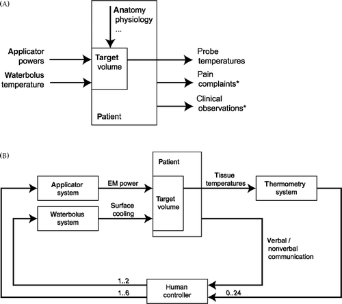
Automatic feedback control of applicator arrays has been proposed in several publications Citation[12–17] and was shown to be effective in phantom models Citation[12], Citation[14], Citation[18]. Such automatic feedback control systems rely on high-density thermal monitoring. When high-density thermometry is not available in the clinic, automatic feedback control based on measured temperatures only becomes less reliable. In this case, patient feedback becomes more important.
Automatic feedback control is not yet feasible in our clinic or in the majority of other clinics. The human factor may introduce inter-individual variability in control performance. To ensure the quality of steering and to stimulate general quality awareness in the hyperthermia team, all treatments are evaluated in multidisciplinary discussion sessions at Erasmus MC. It is our experience that the interpretation of the raw temperature and power data slows down the evaluation process. We therefore have developed a compact and intuitive representation of treatment data, to enable time-efficient and productive treatment evaluations. This treatment evaluation sheet and the treatment evaluation method are presented in this paper.
Hyperthermia treatment evaluation is rarely addressed in the literature. Our intention is to introduce this topic into the quality assurance framework, as it may be critical for the ultimate quality of treatments.
Materials and methods
The evaluation flow as presented in this paper was especially developed for superficial hyperthermia treatments at Erasmus MC. Therefore, a brief description of the treatment approach and equipment used in this clinic is given here.
Patients and treatments
Superficial hyperthermia is used at Erasmus MC in the management of breast carcinoma, melanoma, mesothelioma, and lymph node metastasis of head and neck squamous cell carcinoma. For re-irradiation cases, the hyperthermia target volume is the whole region at risk and encompasses the re-irradiation field. For primary high-dose radiotherapy cases (melanoma), the target volume is macroscopic tumour only. In general, the target volume has a depth of up to 4 cm.
The treatment duration is typically 60 min. The first 20 min are the heat-up period at the end of which the therapeutic temperature should be reached. The aim is to heat the whole target volume to 43°C, but temperatures between 40°–43°C are still considered to be therapeutic. More details about the clinical approach can be found in Citation[19–21].
Applicator system
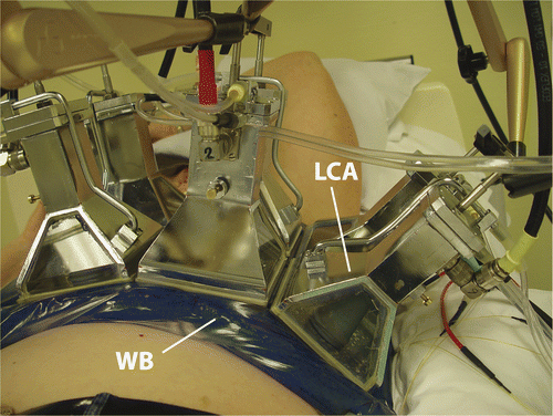
A 433 MHz Lucite cone applicator (LCA) is the standard antenna for superficial hyperthermia at Erasmus MC (). It is a water filled horn applicator that has a high effective field size to aperture ratio due to its Lucite windows and a PVC cone in the horn Citation[22]. The efficiency of this applicator is about 40% Citation[23]. Six LCAs are available. The square aperture makes it easy to combine LCAs in an array. The size of the hyperthermia target volume and the shape of the anatomy determine the array configuration. This ranges from a single applicator (100 cm2) to a 2 × 3 array (600 cm2). For larger areas two applications can be given successively (‘technical fields’). Usually the electric field direction of adjacent applicators in the array is perpendicular for optimum SAR coverage Citation[24]. The E-field direction is rotated 90° for subsequent treatments.
Figure 2. A 2 × 3 LCA array and water bolus (WB) placed on the chest of a patient.
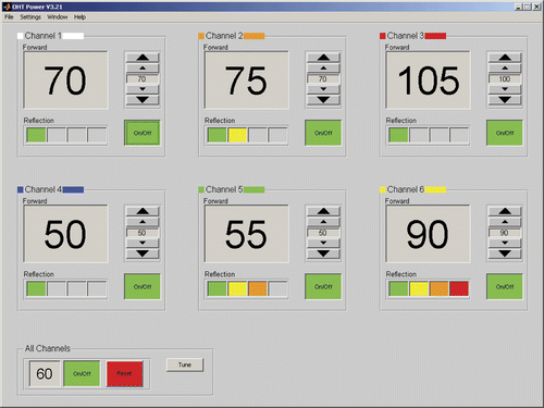
The applicators are fed by power amplifiers with non-coherent sources (Pavoni Diffusion, Rome, Italy) Citation[25]. The amplifiers deliver up to 200 W net incident power per LCA. The technician sets the power levels using a graphical user interface (GUI), see . The interface shows the forward and reflected powers with a refresh rate of one second.
Figure 3. Screenshot of the graphical user interface for power steering. The measured forward power is indicated in large font and the power set point in small font. The reflected powers are represented graphically in a colour code (green <5%, yellow 5–10%, orange 10–15%, red >15% reflected power).
Water bolus system
The function of the water bolus is to couple the electromagnetic waves into the patient and to cool the skin. The water bolus temperature is a steering parameter to control heating at depth: a lower water bolus temperature allows deeper heating because more heat is drawn from the skin surface. A thermocirculator (Polaron E3500, Microtech, West Sussex, UK) flushes the water bolus with de-ionised water of a set temperature. A sensor is placed in the water bolus inlet to monitor the temperature. Several different sized water boluses are available for different LCA array configurations. Clinical guidelines have been developed for the optimal bolus application and for the selection of water bolus temperature as a function of antenna array dimension and target depth Citation[26–27].
Thermometry system
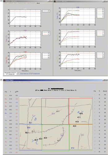
The temperatures are measured with single- and multi-sensor fibre-optic probes (accuracy 0.2°C) using a 24-channel Takaoka FT1310 fibre thermometry readout system (Takaoka Electric, Tokyo, Japan). These non-metallic probes are attached to the skin or inserted into closed-tip interstitial catheters. The aim is to have both interstitial and superficial thermometry under each applicator. The probes are placed in the same location in consecutive treatments. During treatments, the hyperthermia operator monitors the interstitial and skin temperatures using a GUI, see . The GUI shows time—temperature plots for measurement points below each LCA footprint and maps the temperatures onto a representation of the patient anatomy for ease of interpretation. Too high temperatures and steep temperature gradients are highlighted. The refresh rate of the temperature readings is 3 s.
Figure 4. Screenshot of the temperature monitoring graphical user interface. (A) Temperature–time graphs for the sensors below each applicator are shown. (B) The measured temperatures are mapped onto a sketch that includes anatomical features, the location of the tumour and scar tissue, apertures of the applicators, catheter tracks and margins of the radiation field. For each measurement point the tissue type, depth, temperature and temperature difference over 20 s is also shown.
Steering
Steering actions are based on the interpretation of measured temperatures and patient feedback. The actions are directed at achieving therapeutic temperatures (>40°C) throughout the target volume. The maximum allowed tissue temperature is defined in a guideline Citation[28] and differs per tissue type. It ranges from 43°C for normal tissue at first treatment to above 45°C for tumour tissue that is >2 cm distance from normal tissue. To prevent burns, pain complaints prevail over measured temperatures even if these are lower than allowed according to the guidelines.
At the start of the first treatment the power is 30 W per applicator. This can be increased for later treatments. During the heat-up phase in the first 20 min, the target temperature rise is 0.25° to 1°C per minute and the applicator powers are increased in steps of 10 W to achieve this. Smaller steps may be applied if thermometry or tissue sensitivity is limited. After the heat-up phase, small power variations of 5–10 W per applicator are applied to optimise the temperature distribution and to prevent local temperature decreases. The initial water bolus temperature is chosen according to the guideline table published in Van der Gaag et al. Citation[27]. This temperature is varied in 0.5°–1°C steps during water bolus steering.
If temperatures exceed the upper limit, the applicator power is decreased in 5–10 W steps. In case of pain complaints, the technician determines systematically the applicator responsible. The most suspect applicator is switched off and the patient checked as to whether the pain disappears (i.e. power-related hotspot is removed). If the pain is relieved, the antenna is switched on again, but at a lower power level. If the pain does not disappear, it is switched on again to the previous power level and another applicator is switched off. Switching off one applicator at a time for a short period prevents a collapse of the temperature distribution.
Treatment evaluation
Patient discussion
At the start of each week, all treatments performed in the previous week are reviewed in the patient discussion session. Here all disciplines are represented: physicians, technicians and physicists. The basis for the discussion is the measured data presented in the treatment evaluation sheet and the clinical notes made during treatments. The focus is on three questions:
Was the aim of treatment achieved?
What were the limiting factors and anomalies?
Were there tangible indications on how next treatments could be improved for the particular patient?
The action points and issues that develop from the discussion are noted in the patient file. The discussion time needed per patient is typically 4 min, but can be up to about 10 min for special cases.
The primary aim is to optimise treatments for each individual patient. The patient discussion also stimulates the general quality awareness in the hyperthermia unit by serving as a peer review, encouraging interaction between disciplines and steepening the learning curve of new team members. Furthermore, it may initiate new research directions, equipment and procedure quality checks and fine tuning of the clinical guidelines, especially when subjects recur.
Treatment evaluation sheet
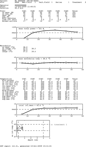
The treatment sheet summarises the steering actions (i.e. applicator power and water bolus temperature settings) and the resulting tissue temperatures in a compact and intuitive way (see for an example). In the graphs, the trend lines and temperature—depth plot enable a fast interpretation of a treatment. The numerical data allow a more in-depth analysis during treatment evaluations.
Figure 5. Example treatment evaluation sheet. Ch, channel; ss, steady-state; int., interstitial; sup., superficial; NaN, not-a-number (no data available).
The treatment sheet is automatically generated as a single-page portable document file (PDF). The treatment sheet repository can be browsed from any computer in the hyperthermia unit and can be used to inspect a patient's earlier treatments or similar treatments from other patients.
The treatment evaluation sheet consists of four sections: general treatment info, power data, water bolus data and tissue temperature data. Power and temperature statistics are reported both for the whole treatment duration (0–60 min) and for the steady-state period (20–60 min).
General treatment information
The general treatment information block contains the patient's name and date of birth, the hyperthermia (HT) number, the number of the medical and technical field, the series number and the treatment number. Also the treatment date, the start time (power-on) and the treatment duration (power-on to power-off) is listed.
Power data
The power data block tabulates the average power and the maximum power per applicator. The last column gives this information for the total power (sum of all channels). The bottom lines mention the number of off-switching events per channel, the total time a channel has been switched off and the number of steering actions (power steps) per channel. Off-switching indicates that limiting factors (pain complaints, high tissue temperatures) have been encountered.
Below the text block is the trend line for the total applicator power. The trend line is centred along its mean value (indicated in the plot), and has a range of mean ± 100 W. Each marker in the trend line represents the 10 min average value. In this way, the shape of the trend line can easily be compared between treatments. The trend lines for water bolus and tissue temperatures are generated in a similar way, and have a range of mean ± 2°C.
Water bolus data
The average water bolus temperature and its range are given and the trend line for water bolus temperature is plotted.
Tissue temperature data
This is subdivided into two parts: interstitial and skin temperatures. Temperature statistics are given per applicator (columns Ch#1.6) and overall (Total). If no probes are available below an applicator's footprint, then not-a-number (NaN) values are shown. For each category the mean, minimum and maximum temperature is indicated.
The trend line indicates how the mean interstitial temperatures developed over time. The temperature–depth plot shows the mean interstitial temperatures during the steady-state period (one dot per measurement point) and the overall mean skin temperature (square marker) and its range during the steady-state period (line). For ease of interpretation, dashed lines indicate the depth of the target volume (0–4 cm in ), the target temperature (43°C) and the minimum therapeutic temperature (40°C). The temperature–depth plot allows the fast interpretation of therapeutic temperatures, heating at depth and the relation between skin temperatures and interstitial temperatures. Results of earlier treatments are indicated by coloured markers in this plot (see ).
Reference data
The reference for evaluation of tissue temperatures is the target (43°C), while values below 40°C are considered insufficient heating. For the water bolus temperature, the reference value is prescribed by our guideline Citation[27], taking into account the effective heating at depth. To create reference values for the evaluation of power steering values, the 2009 clinical data has been analysed (see ). For example, an applicator power of 30 W is considered low and 85 W is high and for the number of steering actions this corresponds to 9 and 29.
Table I. Power steering statistics based on a per applicator analysis of all treatments conducted in 2009 at Erasmus MC (196 treatments, 920 applicator·treatments).
Basic checks
The following basic checks through the treatment sheet provide a systematic way to gain a complete impression of the treatment. The checks refer to the goal of treatment: to heat the whole target volume to the target temperature, unless limitations are met.
Is the data complete? Missing data is clearly indicated by not-a-number values, empty graphs, and messages such as ‘No water bolus data available’. Reasons for incomplete data may be equipment out of order, data files not stored or stored in the wrong place and no thermometry applied.
Was the treatment duration 60 min? A shorter duration may indicate that the treatment was aborted due to serious pain complaints or discomfort.
How much power was applied to the patient? A steady-state mean power of less than 30 W per channel is unusual.
How many off-switching events were there? If there were no switching off events, the power probably was not increased to the limit. Many off-switching events indicate trouble such as a restless patient, frequent pain complaints and severe power limiting hot-spots.
What is the shape of the power trend line? Ideally, it is flat or slightly increasing in the steady-state period.
Was the water bolus temperature stable and according to the guidelines, and if water bolus steering was applied, what was the effect?
What was the steady-state mean interstitial temperature? A mean interstitial temperature between 40°–43°C is satisfactory. If it is below 40°C the temperature may not be therapeutic and the treatment strategy needs to be discussed.
What is the shape of the tissue temperature trend line? Ideally, it is stable at a therapeutic level in the steady-state period. Dips or a negative slope indicate severe limitations. A positive slope after the heat-up phase may indicate too cautious power steering.
What does the temperature–depth distribution look like? Poor heating at depth (or at the surface) shows that water bolus steering should be applied. The temperature–depth plot also clearly indicates whether temperature measurements are available at the deeper sections of the target volume.
What was the treatment limiting factor? If there were no limiting issues such as power-related hot-spots and limiting tissue temperatures that can be identified, heating might be enhanced.
Detail checks
In general, steering and control difficulties are indicated by a high number of off-switching events or steering actions, a significant off period, sub-therapeutic tissue temperatures and a drop of the power level towards the end of treatment. These difficulties often trace back to one or two applicators in the array. Therefore, a detailed analysis commonly focuses on the individual applicators. In addition to the treatment sheet, other sources of information such as time–temperature and time–power plots may be required for more detailed analyses.
Typical trend line and temperature-depth plot shapes
A quick inspection of the trend lines and temperature–depth plots often gives a first impression of the treatment and stimulates questions for evaluations. Common characteristic power, water bolus and tissue temperature trend line shapes are described and illustrated in , and . These trend line shapes and possible checks and actions are discussed in , and , respectively. Common characteristic temperature–depth plots are shown in .
Figure 6. Characteristic shapes of the power trend line: (A) normal, (B) peak at beginning of treatment, (C) continuous increase and (D) decrease at the end of treatment.
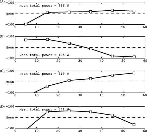
Figure 7. Characteristic shapes of the water bolus trend line: (A) stable and normal, (B) low temperature at the start, (C) wavy and (D) steering.
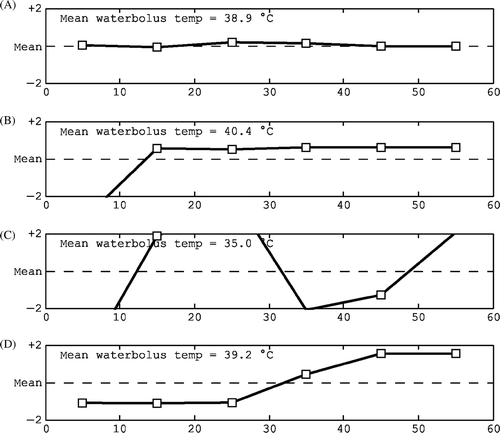
Figure 8. Characteristic shapes of the interstitial temperature trend line: (A) normal, stable, (B) increasing towards the end, (C) decline towards the end, (D) maximum in the early stages and (E) dip in the steady-state period.
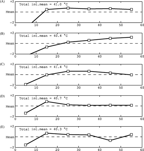
Figure 9. Examples of characteristic temperature–depth plots: (A) all temperatures therapeutic, (B) mix of therapeutic and sub-therapeutic temperatures, (C) sub-therapeutic temperatures, (D) available data only in the top layer with poor coverage at depth, (E) no interstitial data available and (F) relatively high surface and low interstitial temperatures indicating a too high water bolus temperature.
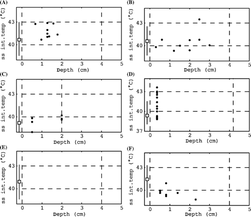
Table II. Characteristics of typical power trend line shapes, the related checks and possible actions for the next treatment.
Table III. Characteristics of typical water bolus temperature trend line shapes, the related checks and possible actions for the next treatment.
Table IV. Characteristics of typical interstitial temperature trend line shapes, the related checks and possible actions during treatment evaluation.
Possible actions to optimise next treatments
Treatment evaluations aim at consistent or improved heating over the course of treatments. Apart from obvious cases, there is no rule-based translation of treatment characteristics into actions for improvement. The action points that roll out of the evaluation usually target:
Applicator set-up. The target volume may be covered by a different number of applicators and sometimes rearranging the array may be needed to avoid hot-spots or to centre an applicator directly above a region that is difficult to heat. The direction of the electric field may be changed by rotating the applicators. Different type applicators may be selected, preferably after a treatment planning case study Citation[29].
Power build-up. The applicator power at start of treatment, the steps during the power increase and the target power in the steady-state period may be redefined.
Water bolus configuration. The water bolus should follow the shape of the body and maintain contact with its surface. Adaptations of the water bolus layer often aim at the prevention of air inclusions.
Water bolus temperature. The guideline temperature is dropped if water bolus steering is required to improve the temperature distribution.
Medication. Pain medication may be prescribed if pain complaints, restlessness or discomfort are not due to power-related high temperatures.
Application of treatment planning. Especially if there are doubts whether a target volume is able to be heated and thermometry is limited, treatment planning provides valuable additional information and may validate proposed changes in the treatment approach.
Discussion
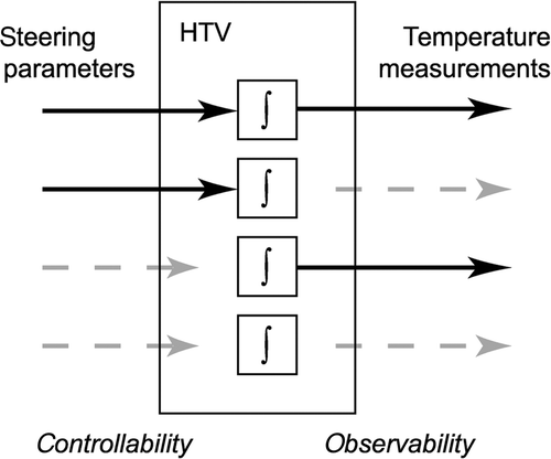
Practical limitations: controllability and observability
In clinical practice, the ability to heat the whole target volume and to observe the temperatures often has its limitations. These two factors, controllability and observability, must be considered during treatment evaluation. A tissue–volume temperature is controllable if it is possible to heat it in a finite time by means of applicator power inputs and water bolus temperature. Low power absorption values, high perfusion rates and power limiting hot-spots may limit controllability. A tissue volume is observable if its temperature can be measured. Observability may be limited by the number of available probes or placement issues such as patient discomfort, anatomical constraints and risk of infection. Note that degrees of controllability and observability may differ within the target volume. For example, both are good in a tissue section near a temperature probe placed centrally below an applicator, but both are poor at 4 cm depth where no interstitial probe can be placed.
In the clinic it may not be possible to make sharp distinctions in the degree of controllability and observability. Therefore, we here focus on the four main cases that are illustrated in :
Good controllability, good observability. The ideal situation where we can heat the volume and observe it. If temperatures are too low, steering actions can directly improve the situation.
Good controllability, poor observability. In principle, tissue can be heated effectively if enough power is applied and the applicator set-up is appropriate. Patient feedback is important here because it replaces measurements. We may conservatively increase applicator power as long as there are no pain complaints.
Poor controllability, good observability – where we know that we were not able to heat appropriately. To improve controllability a different steering strategy or applicator set-up may be applied during the next treatment. The new approach can be evaluated because temperature data is available.
Poor controllability, poor observability. This is difficult as we cannot observe that achieving therapeutic temperatures is a problem. Treatment evaluation may end in pure speculation as measurement data is lacking. Below-average power input to the applicators may indicate suboptimal heating.
Figure 10. Schematic representation of the four main levels of controllability and observability in parts of the hyperthermia target volume (HTV). The blocks marked ∫ represent the tissue dynamics of a HTV subsection. From top to bottom: controllable and observable, controllable and poorly observable, poorly controllable and observable, poorly controllable and poorly observable.
It is tempting to focus on the available temperature data only and unintentionally apply that information also to poorly observable sections. For example, in an earlier study we found in our clinical data that limited observability of temperatures at depth led to too high water bolus temperatures when compared to model output Citation[27]. The evaluation sheet provides clues to take into account poor observability during treatment evaluations as it lists the number of measurement points below an applicator's footprint, prints not-a-number values if no data is available and the data point cloud in the temperature-depth plot clearly indicates coverage at depth.
Non-invasive thermometry greatly enhances observability. Magnetic resonance (MR) imaging is utilised to visualise 3D temperature distributions during deep heating Citation[30–32]. For superficial hyperthermia MR imaging probably may not be an option, for economical and technical reasons. However, temperatures of the tissue top layer can be monitored by non-invasive radiometry Citation[10], Citation[33]. The enhanced observability by non-invasive means also enables more advanced control Citation[34–37].
Hyperthermia treatment planning (HTP) improves both observability and controllability, by showing the expected power distribution or temperature estimates inside the patient and its dependence on steering parameters, applicator set-up and anatomy. The potential of treatment planning in preparing superficial hyperthermia treatments was shown in Citation[29]. Also during treatments, the HTP system may suggest steering actions, or show the effect of intended actions such as to reduce complaints Citation[38]. The clinical merit of HTP-optimised amplitude/phase settings in the heating of oesophageal cancer was evaluated by Kok et al. Citation[39]. HTP-guided steering has been shown to be clinically feasible in deep hyperthermia Citation[40].
Future directions
This paper reflects superficial hyperthermia treatment evaluation at Erasmus MC and although the basic idea can be transferred, the presented treatment evaluation sheet and methods may need adaptations in order to be appropriate for other centres and for other modes of application (e.g. thermal dose prescription, deep hyperthermia). For now, strict criteria for the judgement of treatment quality aspects are lacking. Systematic treatment evaluation however stimulates the exchange of personal opinions the quantification of ideas and effects and eventually, the definition of more objective criteria for good quality hyperthermia treatments.
Besides the treatment sheet, other tools can facilitate treatment evaluations and the analysis of treatment efficacy. To make the course of a treatment fully transparent, the patient feedback, steering actions and measurement data can be visualised and preferably animated in one view, which offers play-back functionality. HTP can play a major role in the evaluation of steering actions and what-if scenarios. Furthermore, the treatment data repository could be integrated into a database of clinical outcome for statistical analysis and data mining.
Quality assurance aspects
Currently, a human operator closes the control loop in virtually all hyperthermia clinics for reasons of safety and complexity of the steering task, combining patient feedback with measurements. Human control undeniably introduces a risk factor in terms of reproducibility between treatments and consistent performance. It might be one of the many factors underlying the large variability in response rates observed in, for example, re-irradiation plus hyperthermia in recurrent breast cancer (21–95%, Citation[20]). The presented treatment evaluation sheet and methods play a role in quality assurance in several ways. First, every patient is discussed in the multidisciplinary team before the next session. The sheet, which is projected on a screen during evaluation, allows a quick interpretation of the treatment data so that the team members who did not carry out the treatment can also fully participate in the discussion. The patient indirectly benefits from the common experience and knowledge of the team and the operators benefit from the peer review. The set of basic checks and the quantitative reference data provide a systematic framework for evaluation. Furthermore, the treatment sheets form a reference set for next treatments. The operator can always browse through them before or during treatments, to check and adjust the steering approach.
A final remark regarding quality assurance is that steering and treatment evaluation are not at all or only slightly addressed in the hyperthermia literature or in the published quality assurance guidelines Citation[41–43]. We propose that the approach described here is merged with that of other clinics and subsequently the common denominator is added to the existing quality assurance guidelines.
Conclusion
A treatment summary sheet was developed for evaluation of superficial hyperthermia treatments. It allows a quick interpretation of a body of data, by graphic presentation of power and temperature trends, a temperature–depth plot, and basic statistics. The sheet, together with a set of basic checks and reference values, supports systematic treatment evaluations during weekly multidisciplinary patient discussions. This ultimately leads to a more consistent performance together with a fine tuned set-up and steering strategy for the individual patient.
Acknowledgements
This study was supported by the Dutch Cancer Society.
Declaration of interest: The authors report no conflicts of interest. The authors alone are responsible for the content and writing of the paper.
References
- Overgaard J, Gonzalez Gonzalez D, Hulshof MCCM, Arcangeli G, Dahl O, Mella O, Bentzen SM. Randomised trial of hyperthermia as adjuvant to radiotherapy for recurrent or metastatic malignant melanoma. Lancet 1995; 345: 540–543
- International Collaborative Hyperthermia Group: Vernon CC, Hand JW, Field SB, Machin D, Whaley JB, Van der Zee J, Van Putten WLJ, Van Rhoon GC, Van Dijk JDP, Gonzalez Gonzalez D, Liu F-F, Goodman P, Sherar M. Radiotherapy with or without hyperthermia in the treatment of superficial localized breast cancer - results from five randomised controlled trials. Int J Radiation Oncology Biol Phys 1996;35:731–744
- Jones EL, Oleson JR, Prosnitz LR, Samulski TV, Vujaskovic Z, Yu D, Sanders LL, Dewhirst MW. Randomized trial of hyperthermia and radiation for superficial tumors. J Clin Oncol 2005; 23: 3079–3085
- Rietveld PJM, Van Putten WLJ, Van der Zee J, Van Rhoon GC. Comparison of the clinical effectiveness of the 433 Mhz lucite cone applicator with that of a conventional waveguide applicator in applications of superficial hyperthermia. Int J Radiat Oncol Biol Phys 1999; 43: 681–687
- Lee WM, Gelvich EA, Van der Baan P, Mazokhin VN, Van Rhoon GC. Assessment of the performance characteristics of a prototype 12-element capacitive contact flexible microstrip applicator (CFMA-12) for superficial hyperthermia. Int J Hyperthermia 2004; 20: 607–624
- Diederich CJ, Stauffer PR. Pre-clinical evaluation of a microwave planar array applicator for superficial hyperthermia. Int J Hyperthermia 1993; 9: 227–246
- Lee ER, Wilsey TR, Tarczy-Hornoch P, Kapp DS, Fessenden P, Lohrbach A, Prionas SD. Body conformable 915 MHz microstrip array applicators for large surface area hyperthermia. IEEE Trans Biomed Eng 1992; 39: 470–483
- Samulski TV, Fessenden P, Lee ER, Kapp DS, Tanabe E, McEuen A. Spiral microstrip hyperthermia applicators: Technical design and clinical performance. Int J Radiat Oncol Biol Phys 1990; 18: 233–42
- Rossetto F, Stauffer PR. Theoretical characterization of dual concentric conductor microwave applicators for hyperthermia at 433 MHz. Int J Hyperthermia 2001; 17: 258–270
- Jacobsen S, Stauffer PR, Neuman DG. Dual-mode antenna design for microwave heating and noninvasive thermometry of superficial tissue disease. IEEE Trans Biomed Eng 2000; 47: 1500–1509
- Juang T, Stauffer PR, Neuman DG, Schlorff JL. Multilayer conformal applicator for microwave heating and brachytherapy treatment of superficial tissue disease. Int J Hyperthermia 2006; 22: 527–544
- Johnson JE, Maccarini PF, Neuman D, Stauffer PR. Automatic temperature controller for multielement array hyperthermia systems. IEEE Trans Biomed Eng 2006; 53: 1006–1015
- Arora D, Skliar M, Roemer RB. Model-predictive control of hyperthermia treatments. IEEE Trans Biomed Eng 2002; 49: 629–639
- Zhou L, Fessenden P. Automation of temperature control for large-array microwave surface applicators. Int J Hyperthermia 1993; 9: 479–490
- VanBaren P, Ebbini ES. Multipoint temperature control during hyperthermia treatments: Theory and simulation. IEEE Trans Biomed Eng 1995; 42: 818–827
- Potocki JK, Tharp HS. Reduced-order modeling for hyperthermia control. IEEE Trans Biomed Eng 1992; 39: 1265–1273
- Cheng KS, Yuan Y, Li Z, Stauffer PR, Maccarini P, Joines WT, Dewhirst MW, Das SK. The performance of a reduced-order adaptive controller when used in multi-antenna hyperthermia treatments with nonlinear temperature-dependent perfusion. Phys Med Biol 2009; 54: 1979–1995
- Kowalski ME, Jin J-M. A temperature-based feedback control system for electromagnetic phased-array hyperthermia: Theory and simulation. Phys Med Biol 2003; 48: 633–651
- Broekmeyer-Reurink MP, Rietveld PJM, Van Rhoon GC, Van der Zee J. Some practical notes on documentation of superficial hyperthermia treatment. Int J Hyperthermia 1992; 8: 401–406
- Van der Zee J, de Bruijne M, Mens JWM, Ameziane A, Broekmeyer-Reurink MP, Drizdal T, Linthorst M, van Rhoon GC. Reirradiation combined with hyperthermia in breast cancer recurrences – overview of experience in Erasmus MC. Int J Hyperthermia. Forthcoming 2010 October
- Van der Zee J, Van Rhoon GC, Broekmeyer-Reurink MP, Reinhold HS. The use of implanted closed-tip catheters for the introduction of thermometry probes during local hyperthermia treatment series. Int J Hyperthermia 1987; 3: 337–345
- Van Rhoon GC, Rietveld PJM, Van der Zee J. A 433 MHz Lucite Cone waveguide applicator for superficial hyperthermia. Int J Hyperthermia 1998; 14: 13–27
- De Bruijne M, Samaras T, Chavannes N, Van Rhoon GC. Quantitative validation of the 3D SAR profile of hyperthermia applicators using the gamma method. Phys Med Biol 2007; 52: 3075–3088
- Rietveld PJM, Lumori MLD, Van der Zee J, Van Rhoon GC. Quantitative evaluation of 2 × 2 arrays of Lucite cone applicators in flat layered phantoms using Gaussian beam predicted and thermographically measured SAR distributions. Phys Med Biol 1998; 43: 2207–2220
- Bakker JF, Paulides MM, Westra AH, Schippers H, Van Rhoon GC. Design and test of a 434 MHz multi-channel amplifier system for targeted hyperthermia applicators. Int J Hyperthermia 2010; 26: 158–170
- De Bruijne M, Samaras T, Bakker JF, van Rhoon GC. Effects of waterbolus size, shape and configuration on the SAR distribution pattern of the Lucite cone applicator. Int J Hyperthermia 2006; 22: 15–28
- Van der Gaag ML, De Bruijne M, Samaras T, Van der Zee J, Van Rhoon GC. Development of a guideline for the water bolus temperature in superficial hyperthermia. Int J Hyperthermia 2006; 22: 637–656
- [Erasmus MC guideline for superficial hyperthermia]. Erasmus MC – Daniel den Hoed Cancer Center, 2004. Dutch. (EMC-DDHCC internal report)
- De Bruijne M, Wielheesen D, Van der Zee J, Chavannes N, Van Rhoon GC. Benefits of superficial hyperthermia treatment planning: Five case studies. Int J Hyperthermia 2007; 23: 417–429
- Gellermann J, Wlodarczyk W, Ganter H, Nadobny J, Fahling H, Seebass M, Felix R, Wust P. A practical approach to thermography in a hyperthermia/magnetic resonance hybrid system: Validation in a heterogeneous phantom. Int J Radiat Oncol Biol Phys 2005; 61: 267–277
- Gellerman J, Hildebrandt B, Issels R, Ganter H, Wlodarczyk W, Budach V, Felix R, Tunn P-U, Reichardt P, Wust P. Noninvasive magnetic resonance thermography of soft tissue sarcomas during regional hyperthermia – correlation with response and direct thermometry. Cancer 2006; 107: 1373–1382
- Van Rhoon GC, Wust P. Introduction: Non-invasive thermometry for thermotherapy. Int J Hyperthermia 2005; 21: 489–495
- Dubois L, Pribetich J, Fabre JJ, Chive M, Moschetto Y. Non-invasive microwave multifrequency radiometry used in microwave hyperthermia for bidimensional reconstruction of temperature patterns. Int J Hyperthermia 1993; 9: 415–431
- Hutchinson E, Dahleh M, Hynynen K. The feasibility of MRI feedback control for intracavitary phased array hyperthermia treatments. Int J Hyperthermia 1998; 14: 39–56
- Stakhursky VL, Arabe O, Cheng K-S, MacFall J, Maccarini P, Craciunescu O, Dewhirst M, Stauffer P, Das SK. Real-time MRI-guided hyperthermia treatment using a fast adaptive algorithm. Phys Med Biol 2009; 54: 2131–2145
- Weihrauch M, Wust P, Weiser M, Nadobny J, Eisenhardt S, Budach V, Gellermann J. Adaptation of antenna profiles for control of MR guided hyperthermia (HT) in a hybrid MR-HT system. Med Phys 2007; 34: 4717–4725
- Cheng KS, Dewhirst MW, Stauffer PR, Das S. Effective learning strategies for real-time image-guided adaptive control of multiple-source hyperthermia applicators. Med Phys 2010; 37: 1285–1297
- Complaint-adaptive power density optimization as a tool for HTP-guided steering in deep hyperthermia treatment of pelvic tumors. Canters RAM, Franckena M, Van der Zee J, Van Rhoon GC. Phys Med Biol 2008;53:6799–6820
- Kok HP, van Haaren PM, van de Kamer JB, Zum Vörde Sive Vörding PJ, Wiersma J, Hulshof MC, Geijsen ED, van Lanschot JJ, Crezee J. Prospective treatment planning to improve locoregional hyperthermia for oesophageal cancer. Int J Hyperthermia 2006; 22: 375–389
- Franckena M, Canters R, Termorshuizen F, Van der Zee J, Van Rhoon G. Clinical implementation of hyperthermia treatment planning guided steering: A cross over trial to assess its current contribution to treatment quality. Int J Hyperthermia 2010; 26: 145–157
- ESHO Quality Assurance Guidelines for Regional Hyperthermia. Lagendijk JJW, Van Rhoon GC, Hornsleth SN, Wust P, De Leeuw ACC, Schneider CJ, Van Dijk JDP, Van der Zee J, Van Heek-Romanowski R, Rahman SA, Gromoll C. Int J Hyperthermia 1998;14:125–133
- RTOG quality assurance guidelines for clinical trials using hyperthermia. Dewhirst MW, Phillips TL, Samulski TV, Stauffer P, Shrivastava P, Paliwal B, Pajak T, Gillim M, Sapozink M, Myerson R, Waterman FM, Sapareto SA, Corry P, Cetas TC, Leeper DB, Fessenden P, Kapp D, Oleson JR, Emami B. Int J Radiat Oncol Biol Phys 1990;18:1249–1259
- Hand JW, Lagendijk JJ, Bach Andersen J, Bolomey JC. Quality assurance guidelines for ESHO protocols. Int J Hyperthermia 1989; 5: 421–428