Abstract
Purpose: To design and test a wideband multi-channel amplifier system for time reversal (TR) microwave hyperthermia, operating in the frequency range 300 MHz–1 GHz, enabling operation in both pulsed and continuous wave regimes. This is to experimentally verify that adaptation of the heating pattern with respect to tumour size can be realised by varying the operating frequency of the antennas and potentially by using Ultra-wideband (UWB) pulse sequences instead of pure harmonic signals.
Materials and methods: The proposed system consists of 12 identical channels driven by a common reference signal. The power and phase settings are applied with resolutions of 0.1 W and 0.1°, respectively. Using a calibration procedure, the measured output characteristics of each channel are interpolated using polynomial functions, which are then implemented into a system software algorithm driving the system feedback loop.
Results: The maximum output power capability of the system varies with frequency, between 90 and 135 W with a relative power error of ±6%. A phase error in the order of ±4° has been achieved within the entire frequency band.
Conclusions: The developed amplifier system prototype is capable of accurate power and phase delivery, over the entire frequency band of the system. The output power of the present system allows for an experimental verification of a recently developed TR-method on phantoms or animals. The system is suitable for further development for head and neck tumours, breast or extremity applications.
Introduction
Several clinical phase III trials have shown that an addition of hyperthermia to radiotherapy or chemotherapy leads to improved clinical outcomes Citation[1–7]. Also, a substantial increase in radiosensitisation with temperature increase has been shown Citation[8], Citation[9] and a strong correlation between clinical results and thermal dose has been demonstrated Citation[6], Citation[10–13]. Building on these positive results, it is reasonable to expect that a system that delivers fine-tuned, narrowly focused power into the tumour will further improve on present treatment outcomes.
Despite substantial progress in the evolution of hyperthermia technologies, including computer codes for detailed numerical modelling used for treatment planning, and introduction of multiple-ring multiple-element applicators Citation[14–17] controlled by highly accurate multi-channel amplifier systems Citation[16], Citation[18], Citation[19], the heat delivery into deep seated tumours has been improved only partially. There are several reports on insufficient temperature increases within the entire volume of deep-seated tumours Citation[2–5], Citation[11]. The main limitation is that spatial focusing is not ideal and leads to problems with hot spot suppression.
The spatial resolution is limited by the regional nature of RF systems with single low frequency excitations. In order to enable sufficient penetration depth, the frequencies are typically in the range 70 to 150 MHz. This type of single frequency set-up is currently the most common for deep-seated tumour hyperthermia Citation[14], Citation[16], Citation[24], Citation[25]. An exception is the recently developed HYPERcollar system Citation[17], designed for head and neck (H&N) tumours and operating at 434 MHz. Unfortunately, the long wavelengths corresponding to the low frequencies mentioned above do not give us the centimetre-scale spatial control which is needed to compensate for the vascular cooling in living tissues, in order to deal with small anatomical structures causing Specific absorption rate (SAR) inhomogeneities and the associated hotspots. For further development, it is thus necessary to use higher frequencies, which yield finer control, but intrinsically lead to challenges with the penetration depth.
Several numerical parameter studies have demonstrated Citation[15], Citation[20–23] that the ability to control the power distribution improves with the number of antennas. On the assumption that amplitudes and phases can be optimally adjusted, the higher the number of antennas, the better the control. Moreover, the optimal operating frequency increases with the number of antennas Citation[15], Citation[20], Citation[21]. As a result of the studies mentioned above, deep hyperthermia system development is moving from single ring antenna applicators with limited control of radiation pattern, through multiple-ring multiple-element systems based on patient-specific modelling, to site-specific applicators Citation[17], Citation[24], Citation[25]. With our approach we continue this trend by developing a flexible applicator, which is tumour volume-specific rather than site-specific. In other words, an applicator that is capable of modifying the focus size depending on the tumour position and volume. The importance of the foci spot size adjustments comes from the ability to restrain hot spots near the tumour, which are difficult to suppress, at the same time as even SAR steering may not be able to maintain high tumour temperatures. An adaptation of the heating pattern can be realised by varying the operating frequency of the antennas and potentially by the use of UWB pulse sequences instead of pure harmonic signals, as used in the present heating equipment. It has been shown in numerical studies by Jacobsen, Converse et al., and Dobšíček Trefná et al. Citation[26–28], that UWB focusing methods offer potential for tighter focusing and a greater reduction of hot spots compared to narrowband techniques. In our previous work we presented a new treatment planning technique Citation[28], Citation[29], based on time-reversal (TR) characteristics of Maxwell equations, which is applicable for both continuous and pulsed waves. In order to evaluate this method experimentally, we have designed and tested a wideband multi-channel amplifier system enabling the use of both single frequency and an UWB pulse regime.
The proposed system, with an overall output power of about 100 W and an operating frequency in the range 300 MHz–1GHz, consists of 12 identical channels driven by a common reference signal. The selected frequency range comes from our earlier simulation studies Citation[28], Citation[29], and from the fact that the system is aimed towards the treatment of H&N tumours and eventual applications on the breast and extremities. The reason for choosing the H&N region is two-fold. Firstly, this region is smaller in comparison with, for example, the pelvic area, but still contains complicated structures with areas requiring protection from heat. Secondly, there is a clinical need for such applicators since there is only one, recently introduced, clinical system intended for the treatment of deep tumours in H&N Citation[17], Citation[30]. Most often hyperthermia treatment in this area is achieved by superficial techniques, which are not optimal for deep-seated tumours.
The decision to use 12 channels in the present prototype was based on the results of our theoretical study Citation[28], where we showed that 12 antennas represent a lower limit of acceptable SAR distribution. This is also in agreement with the choice made by Paulides et al. Citation[23]. Since the purpose of the present system is a validation of the TR approach by phantom measurements, both the number of channels and output power were chosen to be low. However, upgrading of the present system to a clinical version with more channels and high power is straightforward with the replacement of present power amplifiers.
Methods
System general description
shows a schematic overview of the designed system. The oscillator (Agilent, HP 8350, Santa Clara, CA) generates a pure sinusoidal signal of power −10 dBm within a frequency spectrum of 300 MHz to 1 GHz. In the pulsed mode, the oscillator is replaced by an impulse generator (Picosecond Pulse Labs, 3500D, Boulder, CO) producing sequential Gaussian pulses at the power level −10 dBm within a specified frequency range. The low power signal is then pre-amplified by a 26-dB medium power amplifier (MPA) (MiniCircuits, ZFL-1000VH2, Brooklyn, NY) before being split into the 12 channels using a microwave power divider (Pulsar Microwave, P12-03-409, Clifton, NJ).
Figure 1 Wideband hyperthermia system block diagram. PC: personal computer, DAQ: data acquisition module.
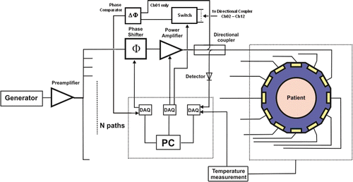
The function of the MPA is two-fold. Firstly, it compensates for the decrease of around 16 dB on the path from the generator to the input power amplifiers (PA). The signal attenuation comes predominantly from the power divider, which reduces the signal amplitudes by 12, and from the cable losses and insertion losses of the components.
Secondly, utilisation of the MPA allows the use of the oscillator at low power output, reducing significantly the harmonic distortions of the generated signal.
The phase in each path can be adjusted by an 8-bit digital phase-shifter with constant time delay for the frequency band used ((Pulsar Microwave, DST-101-480/1 S). Those phase shifters operate in the range 0° to 360° with a minimal resolution of ∼1.4° at centre frequency (650 MHz). The signal is then amplified by a voltage-controlled power amplifier (PA) (EMPower RF Systems, 1043-BBM2C4AAJ, Inglewood, CA) with the frequency- dependent maximum output power in the range 10–12 W. The PA output is connected to the antenna applicator through a bidirectional coupler (Pulsar Microwave, CS30-TBD) with a 30-dB coupling factor. The side arms of all bi-directional couplers in the forward direction are connected to a 12-channel RF switch (Charter Engineering, SP12T, Pinellas Park, FL) with a switching time lower than 20 ms. The common output of the switch is connected to an in-house built power and phase detector, and compared with the reference signal (channel 1). The power and phase detector is developed around the AD8302 (Analog Devices, Norwood, MA), which measures both the gain and absolute phase difference between 0° and 180°. The design of the phase comparator operating in full phase range of 360° is described elsewhere Citation[19]. The power reflected from each antenna is measured by power detectors (Eclipse Microwave, EZR0120), connected to the second arm of the bi-directional coupler. It provides information on the quality of the impedance matching of the antennas and serves to protect the system. When the reflected power exceeds 50% of the requested power level in the channel, the system is automatically turned off. All the microwave components are connected using low-loss cables (Amska Cable, Harbour SS402, Nykvarn, Sweden) with a guaranteed attenuation lower than 0.75 dB/m up to 1 GHz.
The system is fully controlled by a personal computer, interfaced with a graphical environment NI Labview version 8.5 with implemented Matlab routines. The hardware is controlled through three data acquisition modules (DAQ). The first, digital module (NI USB-6509) provides control of the phase shifters, while the voltage controlled PA is driven through the analogue outputs of the second module (NI PCI-670). Data acquired from power detectors and phase comparators is transferred to the analogue inputs of the third module (NI USB-6259). This design is capable of fully controlling 16 channels, intended for the clinical version of the system. In the present version, the remaining free ports can be used to implement additional functions, such as automatic control of local oscillator or temperature control of water bolus and a thermometer sheet.
System calibration
The system has been designed to operate in a wide frequency range, which implies that frequency-dependent phenomena occur. Power level fluctuations and non-linearities associated with signal amplification, insertion losses of the components, cable attenuation and different phase delays along the channels, are examples. To compensate for these effects, a channel-wise calibration procedure, taking into account wide frequency range, has been developed. Since all channels are expected to operate at different power levels, the most important effects to compensate for are the large, power-dependent phase distortions caused by the PA.
The calibration procedure is based on complex S21 parameter measurements of each system channel, using a vector network analyser (VNA) (E8362B, Agilent) as shown in . Port 1 of the VNA is connected to the input of the MPA instead of the local oscillator, and generates a sinusoidal signal which frequency cyclically increases from 300 MHz to 1 GHz in steps of 1 MHz during the calibration process. The frequency resolution of the calibration is thus 1 MHz. The output power is the same as in standard configuration with the local oscillator, i.e. −10 dBm.
Figure 2 Block diagram of the calibration set-up. VNA: Vector Network Analyser, MPA: Medium Power Amplifier, Power Div: Power divider, PA: Power Amplifier, VVA: power amplifier driving voltage.
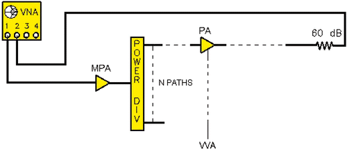
Port 2 is coupled to the output of the channel under calibration, through a 60-dB attenuator (Pasternack Enterprises, Irvine, CA). The power amplifier driving voltage (VVA) is now successively increased from the minimum value of 2.5 V to the maximum of 5 V, in steps of 0.1 V. The S21 measurements with an averaging factor of 16 (i.e. average of 16 single measurements) are performed for each value of VVA and saved in a calibration file. This procedure is then reiterated for each of the 12 system channels.
The power and phase output characteristics are then calculated from the measured S21 parameters and approximated by polynomial functions. This approach results in significantly faster performance of the system software than using look-up tables. While searching for a function which would approximate our measured data, we have noticed that it is advantageous to split the data into two parts and polynomially interpolate the two parts separately. This resulted in a better overall fit and numerically simpler functions. A number of polynomial functions were studied. The goal was to minimise the maximum residuals between the measured output characteristic and approximation polynomials. This is discussed in some detail in the next section.
Results
Power and phase characteristics approximation
shows the maximum approximation errors for the power and phase characteristics for different polynomial orders. Each curve indicates the maximum approximation error among all measured frequency points and all the 12 system channels for the different VVA values.
Figure 3 Absolute power and phase approximation errors (maximum) considering all system channels in the entire working frequency band for different order of approximation polynomials. Note that maximum power output varies from 7.53 W to 10.27 W.
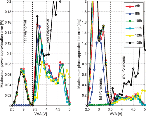
Interpolation of the power output by a single polynomial function gives us errors higher than 10% for low output power values. In the case of phase output, the approximation errors reach 2.5°. Such large inaccuracies are not acceptable and therefore we split the data into two parts and interpolate them separately. For approximation of power characteristics we define the low amplitude part from 2.5 V to 3.4 V and the high amplitude part from 3.4 V to 5 V. Thus the transition happens at 3.4 V. The transition point for the phase characteristic approximation is located slightly higher at 3.5 V. In order to achieve continuity in the overall approximation function, the approximated characteristics at the transition points are constrained to the corresponding measured value. This explains the reduction of errors to zero at transition points.
As can be seen in , the smallest approximation error in power characteristics is obtained by using a ninth order polynomial in the low power regime and a twelfth order polynomial for high powers. The maximum approximation error is less than 0.09 W. demonstrates the maximum approximation error in fitting of phase output characteristics. The tenth order polynomial functions provide the best fit in both low and high power regimes, resulting in a maximum approximation error of 0.19°, with a mean of 0.01°.
System output
Measurements of the maximum output power of the system revealed substantial differences between the different system channels. shows the measured maximum output power for all the system channels as a function of the operating frequency. The output power ranges from a minimum of 7.53 W at 852 MHz on channel 2, to a maximum of 11.3 W at 513 MHz on channel 11. The maximum and minimum variations between channels are 19.3% at 920 MHz and 7.8% at 391 MHz, respectively. The mean value within the entire working frequency band is 12.1%.
Figure 4 Maximum output power values for all the system channels in the working frequency band. The black dotted line represents maximum output power of power balanced system.
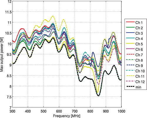
In order to achieve a ‘consistent operation’ of the system, we constrain the maximum power output of all channels to equal the maximum output power of the channel with the minimum power level for each particular frequency. The maximum output power of balanced system then ranges from 7.53 W at 852 MHz to 10.27 W at 563 MHz. The maximum variation within the working frequency band is 26.7%.
Power accuracy
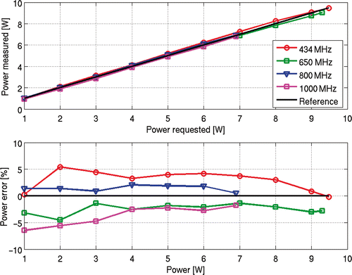
The power accuracy of the system was estimated from the forward power measurements by using an EMC analyser (E7402A, Agilent). The measurements at four selected frequencies (434, 650, 800 and 1000 MHz) were carried out for all 12 channels. The power was increased from 1 W to 10 W or to the maximum available power for the actual frequency in steps of 1 W. The phase target setting was kept at 0°. The power error was then defined as the difference between the power readings of the EMC and the requested power level.
All the system channels were found to perform in a similar manner, and therefore only the results for channel 7 are presented, representing the worst-case scenario. shows the relationship between the measured power and the nominal power level for channel 7. The relative difference between the requested and measured power is presented in . The relative difference between the requested and measured power varies with frequency. The maximum difference is found to stay within the range ±6% for low power levels and within the range ±4% in the case of high power levels.
Phase accuracy
The phase accuracy was estimated from measurement configuration similar to that of the calibration, i.e. by measuring S21 parameters between the system input and the system output. The measurement was undertaken in steps of 10° in the range −180° + 180° for three different power levels (1 W, 5 W, 10 W) using four different frequencies (434, 650, 800 and 1000 MHz). As for the power measurements, all the channels behave in a similar manner and therefore only the results for channel 3 are presented, representing the worst-case scenario.
shows the relative phase errors over the entire phase range, at four selected frequencies. At the centre frequency (650 MHz), the difference between the requested and measured phases is ±1.4°. At the edges of the frequency band (300 MHz, 1 GHz), this inaccuracy increased to ±4°. These errors are power-independent as illustrated in , which shows an almost constant phase error for three different power level settings at frequency 434 MHz.
Figure 6 Measured output phase characteristics for channel 3 at four different frequencies considering a power output of 5 W. PSresol is minimal phase shifter resolution.
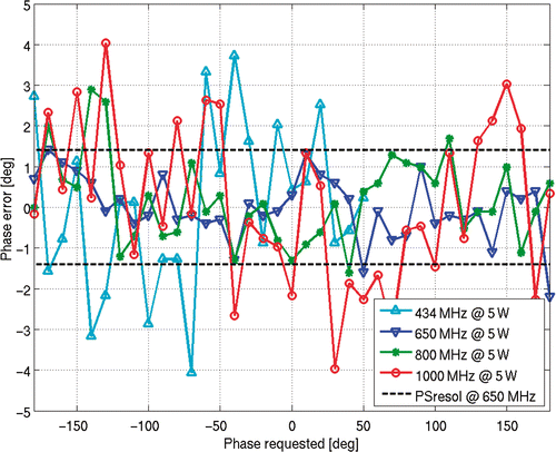
Figure 7 Measured output phase characteristics for channel 3 at three different power levels at frequency f = 434 MHz.
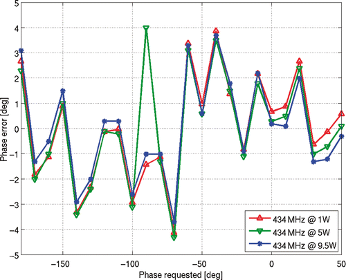
It can also be seen from and that the full phase range of 360° is not achieved for the frequency of 434 MHz. This is the case for all frequencies below the centre frequency of the system, which can be attributed to the phase shifters used in the system. For the pulse-operating mode, the component must keep a constant time delay over the whole frequency range. Due to the linear relation between the phase Φ and time delay Δt (Φ = ω × Δt), the phase range is smaller than 360° for frequencies below centre frequency, as it is larger than 360° for frequencies above centre frequency.
Discussion
In this paper we have presented the design and characteristics of a wideband, multi-channel system prototype for deep hyperthermia treatment operating at a frequency range of 300 MHz to 1 GHz. The system has been designed to enable both continuous and UWB operation modes in order to experimentally verify the potential advantages of the UWB approach. The selected frequency range originates from our simulation studies Citation[28], Citation[29] and from the fact that the system is aimed at the treatment of H&N tumours and eventual applications on the breast and extremities.
Contrary to most of the present clinical amplifier systems Citation[16], Citation[18], Citation[19], which employ the specifically designed direct digital synthesisers (DDS) with a set number of channels, the excitation signal in the proposed prototype is generated by a common generator and then split into 12 paths by a power divider. This approach enables application of both continuous and pulsed wave regimes by using either a local oscillator or an impulse generator. Furthermore, the modularity of this structure allows for cost effective incorporation of extra channels. The power and the phase of each channel is adjustable channel-wise, by independent digital phase shifters and voltage controlled power amplifiers.
In order to ensure system accuracy, power level fluctuations and non-linearities associated with signal amplification have been compensated for by a calibration procedure based on measurements of the complex S21 parameters. The output characteristics of each channel were measured with a VNA of 1 MHz frequency resolution and approximated by polynomial functions with the maximum absolute approximation power error of 1.2%, while the maximum phase error reached 0.2°.
The performance of the system was determined by using external, highly accurate measurement devices, a VNA and an EMC analyser. As a result of the calibration procedure, the relative power error is within ±6% over the entire frequency band of the system. The phase inaccuracy is within ±4° for all power levels throughout the entire frequency band of the system. The system accuracy is comparable with present clinical systems Citation[16], Citation[18], Citation[19] both in terms of power and phase output, within the entire wide frequency band of the system.
The overall output power of the system varies with frequency, between 90 W at 852 MHz and 135 W at 513 MHz. The decrease in amplifier output in frequency range of 720–880 MHz, given by lower gain of the power amplifiers, might negatively affect the pulse regime of the system. A simulation study will be performed in order to quantify distortion of heating pattern with malformed pulses. Depending on the results of this study, the maximum power output of all channels can be constrained to the minimum power level in whole frequency range.
It should be noted that both overall output power of about 100 W as well as output power per channel of about 10 W is insufficient for the intended clinical application. The purpose of the present system is a validation of the TR approach by phantom measurements and eventually animal experiments. However, upgrading of the present system to a clinical version with more channels and high power is straightforward with the replacement of present power amplifiers with market-available, more powerful models. The overall performance of the upgraded system is expected to be comparable with the present system in terms of both power and phase accuracy, as a result of calibration procedure.
An additional phase shifter with a phase range of 0−180° will eventually be introduced in order to allow for the use of the system in full phase range in the continuous case. However, this will happen only if CW regime shows better performance than UWB regime in terms of heating pattern.
The systematic stability of the calibration over time Citation[19], Citation[31] has not yet been established, since the system is not yet meant for clinical use and is not housed in an air-conditioned room. The calibration is nowadays performed before each experimental session. An automatic calibration routine will be implemented and performed with a periodicity which should guarantee output errors within acceptable levels over time. This calibration periodicity will be determined with multiple sections of calibration tests separated in time.
Conclusions
In this paper we have presented the design and characteristics of a wideband, multi-channel system prototype for deep hyperthermia treatment operating at a frequency range of 300 MHz to 1 GHz with an overall output power between 90 W to 135 W, enabling operation in both pulsed and continuous wave regimes.
The developed amplifier system prototype is capable of accurate power and phase delivery, over the entire frequency band of the system. It therefore enables a validation of the multi-frequency and UWB techniques by phantom or animal experiments, in contrast to presently used single frequency approaches. We expect that introduction of a UWB system offers the potential for tighter focusing and a greater reduction of hot spots compared to narrowband techniques.
Declaration of interest: The authors report no conflicts of interest. The authors alone are responsible for the content and writing of the paper.
References
- Valdagni R, Amichetti M, Pani G. Radical radiation alone versus radical radiation plus microwave hyperthermia for N3 (TNM–UICC) neck nodes: A prospective randomized clinical trial. Int J Radiat Oncol Biol Phys 1988; 15: 13–24
- Valdagni R, Amichetti M. Report of long-term follow-up in a randomized trial comparing radiation therapy and radiation therapy plus hyperthermia to metastatic lymph nodes in stage IV head and neck patients. Int J Radiat Oncol Biol Phys 1994; 28: 163–169
- Overgaard J, Gonzalez Gonzalez D, Hulshof MC, Arcangeli G, Dahl O, et al. Randomised trial of hyperthermia as adjuvant to radiotherapy for recurrent or metastatic malignant melanoma. European Society for Hyperthermic Oncology. Lancet 1995; 345: 540–543
- Vernon CC, Hand JW, Field SB, Machin D, Whaley JB, van der Zee J, et al. Radiotherapy with or without hyperthermia in the treatment of superficial localized breast cancer: Results from five randomized controlled trials. International Collaborative Hyperthermia Group. Int J Radiat Oncol Biol Phys 1996; 35: 731–744
- Van der Zee J, Gonzalez Gonzalez D, van Rhoon GC, van Dijk JD, van Putten WL, Hart AA. Comparison of radiotherapy alone with radiotherapy plus hyperthermia in locally advanced pelvic tumours: A prospective, randomised, multicentre trial. Dutch Deep Hyperthermia Group. Lancet 2000; 355: 1119–1125
- Jones EL, Oleson JR, Prosnitz LR, Samulski TV, Vujaskovic Z, Yu D, et al. Randomized trial of hyperthermia and radiation for superficial tumors. J Clin Oncol 2005; 23: 3079–3085
- Issels RD, Lindner LH, Verweij J, Wust P, Reichardt P, Schem BC, et al. Neo-adjuvant chemotherapy alone or with regional hyperthermia for localised high-risk soft-tissue sarcoma: A randomised phase 3 multicentre study. Lancet Oncol 2010; 11: 561–570
- Field SB, Morris CC. The relationship between heating time and temperature: Its relevance to clinical hyperthermia. Radiother Oncol 1983; 1: 179–186
- Dewhirst MW, Viglianti BL, Lora-Michiels M, Hanson M, Hoopes PJ. Basic principles of thermal dosimetry and thermal thresholds for tissue damage from hyperthermia. Int J Hyperthermia 2003; 19: 267–294
- Oleson JR, Samulski TV, Leopold KA, Clegg ST, Dewhirst MW, Dodge RK, et al. Sensitivity of hyperthermia trial outcomes to temperature and time: Implications for thermal goals of treatment. Int J Radiat Oncol Biol Phys 1993; 25: 289–297
- Maguire PD, Samulski TV, Prosnitz LR, Jones EL, Rosner GL, Powers B, et al. A phase II trial testing the thermal dose parameter CEM43° T90 as a predictor of response in soft tissue sarcomas treated with pre-operative thermoradiotherapy. Int J Hyperthermia 2001; 17: 283–290
- Thrall DE, Rosner GL, Azuma C, Larue SM, Case BC, Samulski T, et al. Using units of CEM 43°C T90, local hyperthermia thermal dose can be delivered as prescribed. Int J Hyperthermia 2000; 16: 415–428
- Gellermann J, Hildebrandt B, Issels R, Ganter H, Wlodarczyk W, Budach V, et al. Noninvasive magnetic resonance thermography of soft tissue sarcomas during regional hyperthermia: Correlation with response and direct thermometry. Cancer 2006; 107: 1373–1382
- Turner PF, Schaefermeyer T. BSD-2000 approach for deep local and regional hyperthermia: Clinical utility. Strahlenther Onkol 1989; 165: 700–704
- Kroeze H, Van de Kamer JB, De Leeuw AA, Lagendijk JJ. Regional hyperthermia applicator design using FDTD modelling. Phys Med Biol 2001; 46: 1919–1935
- Crezee J, Van Haaren PM, Westendorp H, De Greef M, Kok HP, Wiersma J, et al. Improving locoregional hyperthermia delivery using the 3-D controlled AMC-8 phased array hyperthermia system: A preclinical study. Int J Hyperthermia 2009; 25: 581–592
- Paulides MM, Bakker JF, Neufeld E, van der Zee J, Jansen PP, Levendag PC, van Rhoon GC. The HYPERcollar: A novel applicator for hyperthermia in the head and neck. Int J Hyperthermia 2007; 23: 567–576
- Wust P, Fang H, Helzel T, Kniephoff M, Wlodarczyk W, Monich G, Felix R. Design and test of a new multi-amplifier system with phase and amplitude control. Int J Hyperthermia 1998; 14: 459–477
- Bakker JF, Paulides MM, Westra AH, Schippers H, Van Rhoon GC. Design and test of a 434 MHz multi-channel amplifier system for targeted hyperthermia applicators. Int J Hyperthermia 2010; 26: 158–170
- Paulsen KD, Geimer S, Tang J, Boyse WE. Optimization of pelvic heating rate distributions with electromagnetic phased arrays. Int J Hyperthermia 1999; 15: 157–186
- Seebass M, Beck R, Gellermann J, Nadobny J, Wust P. Electromagnetic phased arrays for regional hyperthermia: Optimal frequency and antenna arrangement. Int J Hyperthermia 2001; 17: 321–336
- Wust P, Weihrauch M. Hyperthermia classic commentary: ‘Simulation studies promote technological development of radiofrequency phased array hyperthermia’ by Peter Wust et al., Int J Hyperthermia 1996;12:477–494. Int J Hyperthermia 2009; 25: 529–532
- Paulides MM, Bakker JF, Zwamborn AP, Van Rhoon GC. A head and neck hyperthermia applicator: Theoretical antenna array design. Int J Hyperthermia 2007; 23: 59–67
- Wu L, McGough RJ, Arabe OA, Samulski TV. An RF phased array applicator designed for hyperthermia breast cancer treatments. Phys Med Biol 2006; 51: 1–20
- Charny CK, Levin RL. A three-dimensional thermal and electromagnetic model of whole limb heating with a MAPA. IEEE Trans Biomed Eng 1991; 38: 1030–1039
- Jacobsen S. Reduction of hot spots in hyperthermia by means of broadband energy transmission. Electronics Lett 1998; 34: 1901–1902
- Converse M, Bond E, Veen B, Hagness C. A computational study of ultrawideband versus narrowband microwave hyperthermia for breast cancer treatment. IEEE Trans Microwave Theory Tech 2006; 54: 2169–2180
- Dobšíček Trefná H, Vrba J, Persson M. Time-reversal focusing in microwave hyperthermia for deep-seated tumors. Phys Med Biol 2010; 55: 2167–2185
- Dobšíček Trefná H, Vrba J, Persson M. Evaluation of a patch antenna applicator for time reversal hyperthermia. Int J Hyperthermia 2010; 26: 185–197
- Paulides MM, Bakker JF, Linthorst M, van der Zee J, Rijnen Z, Neufeld E, et al. The clinical feasibility of deep hyperthermia treatment in the head and neck: New challenges for positioning and temperature measurement. Phys Med Biol 2010; 55: 2460–2480
- Kongsli J, Hjertaker BT, Frøystein T. Evaluation of power and phase accuracy of the BSD Dodek amplifier for regional hyperthermia using an external vector voltmeter measurement system. Int J Hyperthermia 2006; 22: 657–671
