Abstract
Purpose: The aim of this study is to investigate the effects of ablation parameters on thermal distribution during microwave atrial fibrillation catheter ablation, such as ablation time, ablation power, blood condition and antenna placement, and give proper ablative parameters to realise transmural ablation.
Materials and methods: In this paper, simplified 3D antenna-myocardium-blood finite element method models were built to simulate the endocardial ablation operation. Thermal distribution was obtained based on the coupled electromagnetic-thermal analysis. Under different antenna placement conditions and different microwave power inputs within 60 s, the lesion dimensions (maximum depth, maximum width) of the ablation zones were analysed.
Results: The ablation width and depth increased with the ablation time. The increase rate significantly slowed down after 10 s. The maximum temperature was located in 1 mm under the antenna tip when perpendicular to the endocardium, while 1.5 mm away from the antenna axis and 26 mm along the antenna (with antenna length about 30 mm) in the myocardium when parallel to the endocardium. The maximum temperature in the ablated area decreased and the effective ablation area (with the temperature raised to 50°C) shifted deeper into the myocardium due to the blood cooling.
Conclusion: The research validated that the microwave antenna can provide continuous long and linear lesions for the treatment of atrial fibrillation. The dimensions of the created lesion widths were all larger than those of the depths. It is easy for the microwave antenna to produce transmural lesions for an atrial wall thickness of 2–6 mm by adjusting the applied power and ablation time.
Introduction
Atrial fibrillation (AF) is the most common cardiac arrhythmia. It is associated with stroke and other thrombo-embolic events, left ventricular (LV) dysfunction, heart failure, reduced exercise capacity, degraded quality of life and increased rates of death [Citation1].The estimated prevalence of AF is 0.4% to 1% in the general population and the prevalence increases with age, with approximately 0.5% of people aged 50 to 59 and 9% in the population aged 80 to 89 having AF [Citation2]. Anti-arrhythmic drugs are incompletely effective and associated with dangerous side effects, which limit their long-term use. Surgical cutting is a more permanent and effective means of curing arrhythmias but cannot be popularised mainly due to operative complexity [Citation3]. In recent years, catheter ablation based on maze procedures has become an important alternative approach to cure AF.
Cardiac arrhythmias are mainly due to the presence of abnormal electrical sources or current paths in the cardiac muscle [Citation4]. The presence of AF can be confirmed with an electrocardiogram which demonstrates the absence of P waves together with an irregular ventricular rate. Restoring and maintaining sinus rhythm remains one of the major goals in treating patients with AF. Circumferential pulmonary venous ablation (CPVA) aimed at isolation of pulmonary vein ostia alone or in combination with additional linear ablation of left atrium (LA) has been proved to be one of the most effective strategies to cure AF [Citation5–7]. The ablative treatment is aimed at creating continuous transmural linear lesions to achieve total isolation of the undesirable activation signals in the atrium, and this is one of the important criteria to judge the efficacy of a particular antenna for the cure of AF [Citation8, Citation9]. Radiofrequency (RF) remains the main energy source for the ablative treatment of AF currently [Citation10]. And radiofrequency lesion size is frequently limited by an impedance rise that occurs when the temperature at the electrode–tissue interface reaches 100°C. Thus thermistors are used in the ablation electrode to monitor electrode tip temperature and enables automatic adjustment of the radiofrequency generator output. Irrigated electrodes have been developed to maintain a low electrode-tissue interface temperature during radiofrequency application at high power and prevent an impedance rise, producing deeper and larger lesions [Citation11].
While the RF heating mechanism is primarily due to the currents flowing through electrically resistive tissue, microwave heating is due to the power dissipation of propagating electromagnetic waves, thus making it is not susceptible to tissue charring as occurs in radiofrequency ablation. Microwaves can ablate tissue at greater depth and across a larger volume than RF ablation by increasing the applied microwave power and heat duration, and with a faster temperature rising rate [Citation12, Citation13]. The propagation and radiation of microwaves in biological tissues are governed by frequency, power, and the antenna-radiation pattern, as well as by tissue composition and dielectric permittivity. In thermal therapeutic applications the final temperature may be affected by tissue blood flow and thermal conduction. However, for applications of short duration, the time rate of heating and the spatial distribution of radiated microwave energy are functions of the power deposition (the rate of energy absorption) and the antenna radiation patterns respectively [Citation14]. At present microwaves are rarely used in clinic for the ablative treatment of AF. In order to create the desired lesion pattern, different types of ablation antennas have been proposed. Monopoles and dipoles show a reflection coefficient dependent on the antenna’s insertion depth, and the electromagnetic power deposition extends all along the antenna and its feed line [Citation15–18]. Sleeves or chokes prevent an open circuit to the reflected current flowing backwards along the antenna’s feeding line, thus making the reflection coefficient independent on the antenna insertion depth, and enable the corresponding absorbed power distribution to be more concentrated around the active length of the antenna [Citation19].
Thermal distribution analysis modelling of the virtual surgical environment was investigated to better evaluate the lesion shape under specific conditions. In this paper we employed a finite element method (FEM) to study the thermal field of the proposed expanded tip wire antenna [Citation8] for atrial fibrillation ablation based on the HFSS-ANSYS link (using HFSS and ANSYS mechanical integration). Analysis of lesion dimensions (maximum depth, maximum width) of the ablation zones is carried out to validate whether the proposed microwave antenna can provide long, thin and transmural ablation lesions for the treatment of AF, which can provide useful information to optimise the whole induction heating process.
Method and models
Numerical models
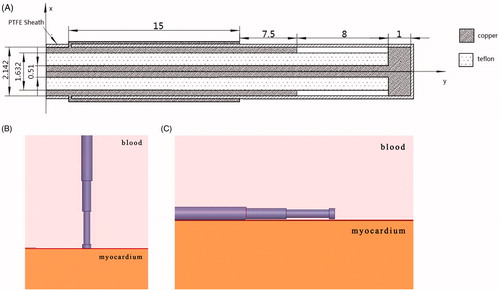
Simplified 3D antenna-myocardium-blood numerical models were built to simulate the endocardial ablation operation. Radiofrequency is the main ablative energy used in clinic while microwave is rarely used for AF treatment. In our research we modelled the configuration of the expanded tip wire antenna reported in the reference [Citation8]. Since the heart is rich in blood, a blood–muscle–antenna model was built using ANSYS HFSS software in our research. The material of the antenna is assumed as copper, and the dielectric material between the inner and outer conduction is Teflon. The dielectric parameters used in the antenna model are shown in Table I. Considering the various antenna locations during the ablation surgery, the antenna was placed in two different ways: perpendicular to the myocardium surface (90°) and parallel to the myocardium surface (0°), shown in .
Figure 1. Antenna configuration and antenna-myocardium-blood numerical models (A) Antenna configuration (mm), (B) Perpendicular to the myocardium surface (90°), and (C) Parallel to the myocardium surface (0°).
Methods
ANSYS HFSS was linked to ANSYS Mechanical within ANSYS Workbench and realised the fully coupled electromagnetic-thermal simulation. Electrical loads computed by HFSS were passed to ANSYS Mechanical, which was used to simulate the temperature increases. In our research, a perfect matching layer boundary condition was employed for the electromagnetic simulation. Wave port was taken as excitation. Considering the influence of power on the following thermal field analysis, 30 W, 40 W, 50 W and 60 W were applied in the electromagnetic simulation respectively. The dielectric and thermal parameters used in the numerical simulation are shown in [Citation20], where ξ is the relative permittivity, σ is the bulk conductivity, β is theattenuation constant, ρ is the myocardial tissue density, c is the specific heat capacity and k is the thermal conductivity.
Table I. Dielectric parameters used in antenna model.
Table II. Dielectric and thermal parameters used in the numerical simulation.
Because each target point is ablated for a short heating time, this research analysed the thermal distribution within 60 s, with time steps of 0.05 s. The electromagnetic analysis in HFSS employed adaptive meshing refinement. The model was discretised into 711,805 tetrahedral elements in ANSYS transient thermal calculation, for which the size of each element is 5.e-004m. The initial temperature is set as 37°C. To avoid overheating, the temperature should be controlled in an appropriate range, usually no higher than 80°C. Thermal parameters changing with increasing temperature is ignored in our research. The rising temperature can lead to the change of electrical conductivity, which is indicated by the following equation:
For myocardium tissue materials, the electrical conductivity of the myocardium varies + 2%°C [Citation21]. So the following parameters are used: a1 = 0.02, a2 = 0, T0 = 37°C.
The mathematical model for temperature elevation in the tissue is based on the Pennes' Bio-heat Transfer Equation, which for homogeneous tissue can be written as follows [22]:
where ρ = tissue density (kg/m3); c. cb = specific heat of tissue and blood (J/kg·°C); k = thermal conductivity of tissue (W/m2·°C);ω b = mass flow rate of blood per unit volume of tissue (kg/s·m3); T. Tb = temperature of tissue and blood (°C); Qm = heat generated by metabolism (W/m3); Qr = heat generated by microwave (W/m3). The heat generated by metabolism and taken away by blood perfusion was ignored in this research compared with high power of the microwave [Citation23–25].
Based on the coupled electromagnetic-thermal theory, the power losses calculated in HFSS electromagnetic field analysis are used as the internal heat generation of thermal analysis within ANSYS Mechanical software to obtain the temperature distribution. It is reasonable to assume that magnetic losses are neglected when dealing with non-magnetic materials. And volume loss density (W/m3) attributed to dielectric losses:
where PLd is average dielectric power loss, ξ 0 is the permittivity of free space, ξr is the imaginary part of material permittivity and represents losses,
denotes electric field, and V is the volume of dielectric.
Numerical results
Effect of thermal cooling at the endocardium
The formation of ablation lesion depends on the thermal distribution inside the tissues. Ablation is obtained when the target tissue temperature exceeds 50°C for a few seconds; 50°C is taken as the threshold for lesion formation according to the physical response of tissues and cells to heating [Citation26]. FEM simulation predicts the process of the ablation from power delivered, heat duration, geometry, material characteristic and myocardial properties. The blood flow in the heart chambers also plays an important role in lesion formation during thermal ablation. As different locations were ablated in surgical ablation of atrial fibrillation, different convection coefficients between blood and cardiac tissue were adopted, representing different blood flow conditions, shown in [Citation27, Citation28].
Table III. Convective heat transfer coefficient in different applied locations.
In our numerical model, the convection boundaries were applied at two areas of contact between the blood and muscle or antenna respectively. shows the temperature field of the microwave antenna and the cardiac muscle when the convection coefficient is 1,417 W/m2°C (blood–muscle contact interface), 6,090 W/m2°C (blood–antenna contact interface) [Citation29]. The antenna has convective heat transfer with the blood and heat conduction with the myocardium.
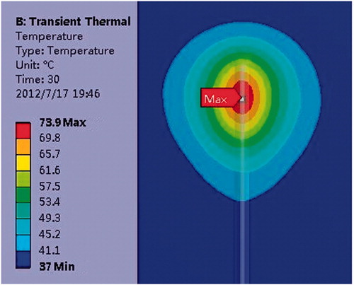
Figure 2. Effect of thermal cooling at the endocardium (A) Antenna temperature, (B) 1417 W/(m2·°C), (C) No blood flow exists, (D) Antenna temperature, (E) 1417 W/(m2·°C), and (F) No blood flow exists.
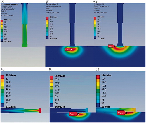
The heat can be conducted from the myocardium into the antenna via the interface between the myocardium and antenna. B and C compared the temperature distribution under a convection coefficient of 1,417 W/(m2·°C) and no blood flow condition. Simulation results show that the lesion shape appears as a bowl when no blood flow exists (MW epicardial ablation), shown in C. With the increase of the convective heat transfer coefficient, the margin of the lesion area shaped an arc in the myocardial tissue (B). The maximum temperature point is not located at the myocardium surface where maximum electromagnetic power is absorbed in the myocardium, shown in B. The maximum temperature in the myocardium tissue decreased significantly compared with no-blood condition (B, C). The hottest point of the lesion shifted deeper into the myocardium from the endocardial surface. When the antenna is perpendicular to the endocardium, the maximum temperature point is located at 1 mm under the antenna tip in the myocardium. When it is parallel to the endocardium, the maximum temperature appeared at 1.5 mm away from antenna axis and 26 mm along the antenna.
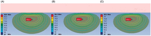
The lesion size presents a decreasing tendency with the increasing convective heat transfer, shown in . The effective ablation area (with the temperature above 50°C) shifted deeper into the myocardium and a thin low-temperature layer appeared at the endocardium (C). The maximum temperature in the ablated area decreased with the increase of the convective heat transfer coefficient, which values were 74.0°C, 70.7°C, 69.4°C respectively, with an input power of 30 W and heat duration of 30 s, and 86.7°C, 82.2°C, 80.5°C when the applied power is 40 W and the ablation time is 30 s (perpendicular to the endocardium).
Figure 3. Thermal distributions with different convective heat transfer coefficient (30 W, 40 s).,(A) 1,417 W/(m2·°C), (B) 3,550 W/(m2·°C), and (C) 7,100 W/(m2·°C).
Analysis of lesion dimensions in the myocardium tissue
The initial temperature of the tissue is set as 37°C. As short time is needed at each target point in ablation procedure for the treatment of AF, the thermal distributions of the myocardium at 10, 20, 30, 40, 50, and 60 s are acquired. shows lesion areas changing with the increasing ablation time (P = 30 W, t = 20 s, 40 s, 60 s). The convection coefficient at the blood and muscle contact interface is 7,100 W/(m2·°C).
Figure 4. Lesion area with increasing time (P = 30 W) (A) Perpendicular to the endocardium and (B) Parallel to the endocardium.
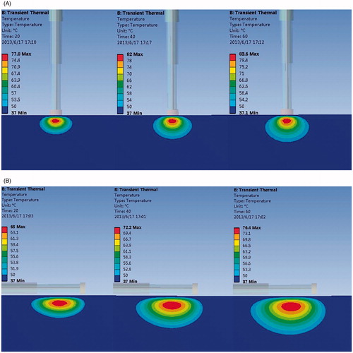
To cure AF, long, thin and transmural ablation lesions along trajectories similar to those created by maze surgical procedures are needed. We can see that the ablation width and depth dimensions increased with the ablation time. The maximum depth and maximum width of the lesion zones with different ablation time and power were obtained. Numerical results show that the lesion shape appears approximately an ellipsoid from top view, shown in , with lesion width larger than depth. The ablation area shape meets the requirements of AF ablation surgery and tends to form continuous, long, linear lesions. Ratio of its width to depth decreased with ablation time increasing when the applied power was 30 W (parallel to the endocardium). The value was 3.50, 2.64, 2.39, 2.22, 2.08, and 2.07 respectively with the corresponding heating time10, 20, 30, 40, 50, and 60 s.
Figure 5. Top view of lesion area.
The change rule of lesion dimension with ablation time under different applied power conditions has been analysed. The relationship between lesion dimensions and ablation time or applied power helps the preference of ablative parameters such as the heating time required, the applied power, for example. It provides important preoperative information for planning AF treatment. As can be seen from the results, with the increase of ablation power both the ablation depth and width increased. In the first 10 s of the heating process the depth and width changed significantly. For example, when the antenna was perpendicular to the myocardium surface, the ablation width reached 4 mm, and the ablation depth reached 2 mm within the first 10 s (30 W). When the ablation time reached 20 s, the ablation width was 5 mm, and the ablation depth was 2.7 mm, which means that the ablation width increased by 1 mm, and the depth 0.7 mm during 10–20 s. The increase rate significantly slowed down 10 s later, shown in and , with the x axis representing ablation time and y axis representing the lesion depth or width.
Figure 6. Width changes with increasing heating time (A) Perpendicular to the endocardium and (B) Parallel to the endocardium.
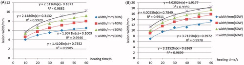
Figure 7. Depth changes with increasing heating time (A) Perpendicular to the endocardium and (B) Parallel to the endocardium.
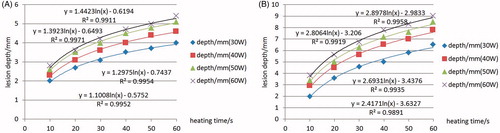
Comparison of width or depth changing with increasing ablation time at different powers is also discussed. The lesion depth and width increments eased when increasing applied power. The simulation results present a positive correlation between the maximum temperature in the myocardium and the ablation power, which is in agreement with the report in reference [Citation3]. An equal increase in maximum temperature appeared with the power increased by 10 W.
AF ablation success and complication rates may be related to regional differences in LA wall thickness. Anatomical studies [Citation3] have shown that the superior wall, or dome, is the thickest part of LA (3.5–6.5 mm), whereas the anterior wall just behind the aorta is usually the thinnest (1.5–4.8 mm). In order to get the desired lesion depth corresponding to different atrial wall thickness and meanwhile prevent overheating (usually no higher than 80°C), ablation parameters to get the required depths corresponding to different cardiac tissue thickness were analysed.
The recommended ablative parameters were given as to different atrial wall thickness: 2 mm, 3 mm, 4 mm, 5 mm and 6 mm, shown in , including the ablation time, the ablation power, the corresponding maximum temperature and antenna placement angle. We can see that, when the required depth is 3 mm, a heating time about 10 s can realise the transmural ablation, meanwhile keeping the hottest point not too high (65°C), and the depth/width value is about 1/3.0, tending to form a linear, continuous lesion area. The antenna placement angle of 0° may be more capable of creating greater ablation depth and making more effective use of the electromagnetic energy.
Table IV. Applied power and ablation time with different requiring lesion depth.
Conclusion and discussion
In this paper thermal distribution of MW ablation for atrial fibrillation was obtained by coupled electromagnetic-thermal analysis based on FEM. Lesion dimensions (maximum depth, maximum width) of the ablation zones were analysed.
Results show that the created lesion widths were all larger than the depths, which validated that the microwave antenna can provide continuous long and linear lesions for the treatment of AF. The ablation width and depth increased with the ablation time. The increase rate significantly slowed down 10 s later. Comparing the thermal distribution in the blood condition with that in no-blood condition, the maximum temperature in the myocardium tissue decreased significantly and the highest temperature point of the lesion shifted deeper into the myocardium from the myocardium surface. The effective ablation area (with the temperature above 50°C) shifted deeper into the myocardium, and a thin low-temperature layer appeared at the endocardium (C). The cooling down layer could be eliminated gradually by increasing the ablation time or applied power.
Relationships between the lesion dimension and ablation time or applied power were investigated. The conclusion can be reached that it is easy for the MW antenna to get transmural lesions for an atrial wall thickness of 2–6 mm by adjusting the applied power and ablation time. The simulation results present a positive correlation between the maximum temperature in the myocardium and the ablation power. An equal increase in maximum temperature appears with the power increasing by 10 W. Different antenna- placement styles can also affect the lesion shape and location of the hottest spot: 1.0 mm deep into cardiac tissue when the placement angle is 90° (perpendicular to the endocardial surface), while 1.5 mm away from the antenna axis when the antenna placement angle is 0° (parallel to the endocardial surface). Results show that the antenna placement angle of 0° is more capable of creating larger ablation depth when the required depth is greater than 4 mm. The placement angle of 0° may be more effective in creating a deeper lesion for thicker atrial wall and a larger width/depth ratio than 90°. Transmural lesions are easy to create corresponding to different atrial wall thicknesses. Antenna placement, ablation time and applied power can be adjusted depending on the various thickness and blood flow conditions in different areas.
The thermal distribution can be used to evaluate rationality of antenna design and help antenna optimisation. However, more accurate modelling of a virtual surgical environment should be built to establish a stable base for surgery planning, surgery rehearsal and telesurgery. Real-time thermal distribution by numerical simulation has always been a difficulty due to time-consuming calculation. A database describing thermal distribution under various surgical environmental conditions may be an appropriate solution to help patient-specific treatment plans.
As a series of target points are ablated during AF catheter ablation procedure and the ablation conditions at different locations vary from patient to patient due to individual difference and pathological difference, such as the various blood flow conditions caused by pathological changes, the various atrial wall thickness in different parts of the heart, and the fat layers during MW epicardial ablation, for example. Simple in vitro experimentation is not possible for modelling these complicated individual pathological and physiological diversities. Since it is impractical to do testing experiments on human tissue and organ, numerical simulations can model the ablation environment by geometric reconstruction and setting human tissue material properties. It provides a way to evaluate lesion size and solves the problem of individual differences. However, many factors may induce difference between experimental and numerical simulation results, such as blood flow conditions, differences in electrical and thermal properties, and the atrium wall thickness. In our study the thermal and physical properties were assumed constant over temperature and the tissue conductivity is slightly increased as a function of temperature [Citation21]. However, more recent works [Citation25,Citation30] have reported a different behaviour of the conductivity with temperature measured in liver tissue (decreasing for higher temperatures). A rapid decrease in both relative permittivity and conductivity was observed from 70 to 100°C. And a sigmoidal model more accurately predicted high temperatures noted near the antenna at higher input powers [Citation30]. The change of dielectric properties may reduce the antenna efficiency and affect the size and shape of the thermal lesion. In fact, other parameters such as thermal conductivity, specific heat capacity and tissue density coefficient may change as a function of temperature and have an influence on the lesion formation as well. The thermal, physical, and dielectric properties changing pattern with temperature increasing should be studied in detail to improve simulation of MW temperature distribution. The parameters influencing the temperature field must be decided through all-around analyses, which may be not independent, and a combination of the different factors influencing the temperature field will be carried out in our future work.
The research validated the possibility of MW application in AF treatment. Microwave heating offers the advantages of heating a deeper volume of tissue with more precise control than thermal conduction of RF electrode heating. However, the efficacy, controllability, and security of MW application in AF still need to be improved. The antenna spacing under different applied power and heat duration conditions will be investigated to form a continuous linear lesion for AF ablative treatment. In order to realise transmural ablation, the ablation time and the ablation power under other different antenna placement angle conditions should be established. Experiments should be done to validate the simulation result, and the maximum temperature should be recorded to avoid overheating in the experiment.
Declaration of interest
This research was supported by National Science Foundation of China (No.31070754), Beijing talent cultivation plan (2010D005015000006), Doctor Start-up Foundation of Beijing University of Technology (X0015999201101) and Beijing Municipal Commission of Education Project Key Scientific and Technological Program (KZ201210005006). The authors alone are responsible for the content and writing of paper.
Acknowledgement
The authors thank Qun Nan and Youjun Liu for their kind advice and guidance.
References
- Camm AJ, Kirchhof P, Lip GY, Schotten U, Savelieva I, Ernst S, et al. Guidelines for the management of atrial fibrillation: The Task Force for the Management of Atrial Fibrillation of the European Society of Cardiology (ESC). Eur Heart J 2010;31:2369–429
- Vergara P, Picardi G, Nigro G, Scafuro F, de Chiara A, Calabro R, et al. Evaluation of thyroid dysfunction in patients with paroxysmal atrial fibrillation. Anadolu Kardiyol Derg 2007;7:S104–6
- Liu X. Catheter Ablation of Atrial Fibrillation. Shanghai: Shanghai Jiao Tong University Press, 2009
- McRury ID, Haines DE. Ablation for the treatment of arrhythmias. Proc IEEE 1996;84:404–16
- Wang XH, Liu X, Sun YM, Shi HF, Zhou L, Gu JN. Pulmonary vein isolation combined with superior vena cava isolation for atrial fibrillation ablation: A prospective randomized study. Europace 2008;10:600–5
- Wright M, Haissaguerre M, Knecht S, Matsuo S, O'Neill MD, Nault I, et al. State of the art: Catheter ablation of atrial fibrillation. J Cardiovasc Electrophysiol 2008;19:583–92
- Hsieh MH, Tai CT, Lee SH, Lin YK, Tsao HM, Chang SL, et al. The different mechanisms between late and very late recurrences of atrial fibrillation in patients undergoing a repeated catheter ablation. J Cardiovasc Electrophysiol 2006;17:231–5
- Chiu HM, Mohan AS, Weily AR, Guy DJ, Ross DL. Analysis of a novel expanded tip wire (ETW) antenna for microwave ablation of cardiac arrhythmias. IEEE Trans Biomed Eng 2003;50:890–9
- Nattel S. Therapeutic implications of atrial fibrillation mechanisms: Can mechanistic insights be used to improve AF management? Cardiovasc Res 2002;54:347–60
- Berjano E. Theoretical modeling for radiofrequency ablation: State-of-the-art and challenges for the future. Biomed Eng Online 2006;5:24
- Nakagawa H, Yamanashi WS, Pitha JV, Arruda M, Wang X, Ohtomo K, et al. Comparison of in vivo tissue temperature profile and lesion geometry for radiofrequency ablation with a saline-irrigated electrode versus temperature control in a canine thigh muscle preparation. Circulation 1995;91:2264–73
- Habash RW, Bansal R, Krewski D, Alhafid HT. Thermal therapy, Part III: Ablation techniques. Crit Rev Biomed Eng 2007;35:37–121
- Li X, Zhang L, Fan W, Zhao M, Wang L, Tang T, et al. Comparison of microwave ablation and multipolar radiofrequency ablation, both using a pair of internally cooled interstitial applicators: Results in ex vivo porcine livers. Int J Hyperthermia 2011;27:240–8
- Lin JC. Electromagnetics for the heart. IEEE Antenn Propag Mag 2002;44:103–05
- Lin JC, Bernardi P, Pisa S, Cavagnaro M, Piuzzi E. Antennas for medical therapy and diagnostics. In: Balanis C, ed. Modern Antenna Handbook. New York: J. Wiley & Sons, 2008, pp. 1377–428
- Bertram JM, Yang D, Converse MC, Webster JG, Mahvi DM. A review of coaxial-based interstitial antennas for hepatic microwave ablation. Crit Rev Biomed Eng 2006;34:187–213
- Brace CL, Laeseke PF, van der Weide DW, Lee FT. Microwave ablation with a triaxial antenna: Results in ex vivo bovine liver. IEEE Trans Microw Theory Tech 2005;53:215–20
- Nevels RD, Arndt GD, Raffoul GW, Carl JR, Pacifico A. Microwave catheter design. IEEE Trans Biomed Eng 1998;45:885–90
- Cavagnaro M, Amabile C, Bernardi P, Pisa S, Tosoratti N. A minimally invasive antenna for microwave ablation therapies: Design, performances, and experimental assessment. IEEE Trans Biomed Eng 2011;58:949–59
- Bernardi P, Cavagnaro M, Lin JC. Distribution of SAR and temperature elevation induced in a phantom by a microwave cardiac ablation catheter. IEEE Trans Microw Theory Tech 2004;52:1978–86
- Foster KR, Schwan HP. Dielectric properties of tissues and biological materials: A critical review. Crit Rev Biomed Eng 1989;17:25–104
- Tungjitkusolmun S, Cao H, Tsai JZ, Vorperian VR, Webster JG. Finite element analyses of uniform current density electrodes for radio-frequency cardiac ablation. IEEE Trans Biomed Eng 2000;47:32–40
- Diederich CJ. Thermal ablation and high-temperature thermal therapy: Overview of technology and clinical implementation. Int J Hyperthermia 2005;21:745–53
- Jain RK. Temperature distribution in normal and neoplastic tissues during normothermia and hyperthermia, in thermal characteristics of tumors: Applications in detection and treatment. Ann NY Acad Sci 1980;335:48–62
- Ji Z, Brace CL. Expanded modeling of temperature-dependent dielectric properties for microwave thermal ablation. Phys Med Biol 2011;56:5249–64
- Diederich CJ. Thermal ablation and high-temperature thermal therapy: Overview of technology and clinical implementation. Int J Hyperthermia 2005;21:745–53
- Lai YC, Choy YB, Haemmerich D, Vorperian VR, Webster JG. Lesion size estimator of cardiac radiofrequency ablation at different common locations with different tip temperatures. IEEE Trans Biomed Eng 2004;51:1859–64
- Berjano EJ, Hornero F. Thermal-electrical modeling for epicardial atrial radiofrequency ablation. IEEE Trans Biomed Eng 2004;51:1348–57
- Lu YL, Nan Q, Li L, Liu YJ. Numerical study on thermal field of microwave ablation with water-cooled antenna. Int J Hyperthermia 2009;25:108–15
- Lopresto V, Pinto R, Lovisolo GA, Cavagnaro M. Changes in the dielectric properties of ex vivo bovine liver during microwave thermal ablation at 2.45 GHz. Phys Med Biol 2012;57:2309–27