
Abstract
Air-backed transducers have been employed for thermal ultrasonic treatment including both ablation and hyperthermia because the power efficiency rather than the bandwidth is a main concern, unlike a typical imaging transducer working in a pulse mode. The characteristic of an air-backed piezoelectric transducer with a matching layer is analysed, and the role and choice of the matching layer is discussed. An element size of a focused array transducer, appropriate for such thermal treatment, is then estimated, and the characteristic of a piezoceramic transducer element of such a size was numerically analysed using a finite element code. The characteristic of a piezocomposite transducer element is also numerically analysed and its suitability to such a therapeutic array transducer is discussed.
Introduction
A transducer is the most important key component for therapeutic ultrasound treatment including both thermal and mechanical treatments. The former includes high-intensity focused ultrasound (HIFU) treatment and ultrasonic hyperthermia, and the latter may include lithotripsy, histotripsy, and even sonoporation and sonodynamic therapy. Ultrasonic physiotherapy may be included by both treatments. Therapeutic ultrasound treatment can also be categorised into those employing either focused or unfocused ultrasound. Focused ultrasound mechanical treatment such as lithotripsy and histotripsy uses pulsed ultrasound with a wide relative bandwidth close to that for ultrasonic imaging. The reason is that cavitation can be induced in an uncontrolled manner and unwanted adverse effects might be caused if a long burst ultrasound is reflected by the bubbles created by the earlier part of the burst. Unlike these applications, however, continuous wave (CW) or long burst ultrasound is used for thermal ultrasonic treatment.
Unlike a typical imaging transducer working in a pulse mode, an air-backed transducer is employed for thermal ultrasonic treatment because the power efficiency rather than the bandwidth is a main concern. An air-backed piezoceramic single element transducer and an air-backed piezocomposite array transducer have been typically used for focused ultrasound thermal treatment. The former has been employed in the two approved systems for the transrectal treatment of prostate [Citation1–3] and the latter in the approved system for the extracorporeal treatment of uterus and breast [Citation4,Citation5]. The guiding principles and considerations for designing such typical focused transducers for thermal treatment are reviewed in this paper. Several papers have been published on the design of such transducers [Citation6–12], but the guiding principles have not been well summarised. The guiding principles and considerations are significantly different from those for imaging transducers, and therefore important to be clearly explained. This is attempted in this paper under certain assumptions reasonably applied in practice.
Choice of ultrasonic frequency
The optimum ultrasonic frequency for thermal treatment is estimated in this section [Citation13,Citation14]. Here, the volume of the target tissue to be treated is assumed to be much larger than that of the ultrasonic focal spot, which requires focal spot scanning and/or broadening. This assumption can be applied to typical HIFU treatments such as those of prostate tumours [Citation3] and uterine myomas [Citation5]. In this case the optimum frequency simply corresponds to what maximises the heat deposition at the target tissue depth.
It can be approximated that the ultrasonic attenuation and absorption of both target and intervening tissues have the same frequency dependence as in Equation Equation1(1)
(1)
where f is the ultrasonic frequency, α and β are the attenuation and absorption coefficient, respectively, and β0 is assumed to be constant. The ultrasonic power, after propagating through a tissue depth of L, can be described as in Equation Equation2
(2)
(2)
where W0 is the incidental power. Here, potential non-linear effects such as non-linear propagation and absorption are ignored. Then, the heat generation per propagation length can be derived from Equation Equation2
(2) substituted with 1 as in Equation Equation3
(3) .
(3)
The optimum frequency, f0 at which the heat generation will be maximised, is obtained from Equation Equation4(4)
(4)
as in Equation Equation5
(5)
(5)
In a typical case when the attenuation coefficient is approximated [Citation15] as in Equation Equation6(6)
(6)
the optimum frequency can be approximated as in Equation Equation7
(7) .
(7)
Choice of F-number
In a typical high-intensity focused transducer, an F-number of about 1 is preferred. In other words, the diameter of the transducer aperture, DA, close to the focal length, F, tends to be chosen. There may be several reasons for this choice of F-number, or F/DA.
The geometrical selectivity by focusing will be quickly degraded when the F-number exceeds 1 because the axial length of the focal region, ΔF, is proportional to the square of the F-number as in Equation Equation8(8)
(8)
where λ is a wavelength in tissue. Conversely, a large acoustic window, allowing an F-number to be much smaller than 1, is not available for the target tissue to be treated in most cases because of gas bodies or bones disturbing ultrasound propagation.
Tissues such as breast are rare exceptions. For breast, even an aperture surrounding it may be used, but the aberration correction may be needed for focusing with such an extremely small F-number. When aberration correction is successfully applied, focusing with a small F-number even through the skull bone is possible [Citation16]. These are regarded as out of the scope of this paper.
From Equation Equation7(7) , the aperture diameter for high-intensity focused thermal treatment with an F-number close to unity is chosen as in Equation Equation9
(9) .
(9)
One-dimensional model of air-backed transducer
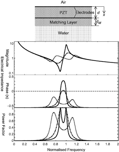
A typical single-element transducer has its thickness much smaller than both dimensions of its aperture. Therefore the primary characteristics of an air-backed single-element transducer can be analysed by using a one-dimensional model as shown in the schematic in , where d and dM are the thickness of the piezoelectric plate and the matching layer, respectively. In the following analysis the dielectric loss of the piezoelectric material and the mechanical loss of all materials are ignored. The acoustic pressure, p(x), in the piezoelectric plate can be described [Citation17] as in Equation Equation10(10)
(10)
where
is the acoustic wave number, D is the electric displacement, and
is the piezoelectric constant. Here, ρ, κ, ɛ and K are the density, the bulk modulus, the dielectric constant, and the electromechanical coupling constant of the piezoelectric, respectively. Because it is air-backed,
. Using this boundary condition, Equation Equation10
(10) can be solved as Equation Equation11
(11)
(11)
where
. The particle velocity can also be obtained as in Equation Equation12
(12) .
(12)
Figure 1. Electrical impedance of air-backed piezoceramic transducer with matching layer. Solid curve, no matching layer; chained curve, with a matching layer optimised for the power factor; dotted curve, with a conventional matching layer.
From Equation Equation12(12) we can get Equations Equation13
(13) and Equation14
(14) .
(13)
(14)
Regarding the matching layer as an acoustic transmission line, one can get Equation Equation15(15)
(15)
where
,
, and ZM and ZW are the acoustic impedance of the matching layer and water, respectively. Here, kM is the wave number in the matching layer.
The current through the transducer is then obtained by combining Equations Equation13(13) and Equation15
(15) as in Equation Equation16
(16)
(16)
where Z and A are the acoustic impedance and the area of the piezoelectric plate.
The voltage across the transducer can be obtained by taking the integral of the electric field form x = 0 to d as in Equation Equation17(17)
(17)
where X(x) is the mechanical displacement. By substituting Equations Equation13
(13) , Equation14
(14) , and Equation15
(15) , one can get Equation Equation18
(18) .
(18)
The electrical impedance of the transducer is finally obtained from Equations Equation15(15) and Equation18
(18) as in Equation Equation19
(19) .
(19)
Choosing a typical piezoelectric material such as PZT-4, the electrical impedance of the transducer was calculated and the results are plotted in . For the electromechanical coupling constant, K, and the acoustic impedance, Z, those of the thickness mode, Kt = 0.5 and Z = 30 MRayl, were used, respectively. Not only are the magnitude and phase of the electrical impedance shown, but also the power factor. This factor equals to the acoustic output power divided by the apparent electric input power, and therefore is the most important factor for a high-intensity transducer for thermal treatment. This factor is easily calculated as the cosine of the phase of the electrical impedance.
Choice of matching layer
In three curves are plotted in each frame: (1) with no matching layer, (2) with a matching layer optimised for the power factor, and (3) with a conventional matching layer.
The angular frequency maximising the magnitude of electrical impedance with no matching layer, called the anti-resonance angular frequency, is approximated by Equation Equation20(20)
(20)
corresponding to the mechanical resonance frequency of the piezoelectric plate without piezoelectricity. Frequency on the horizontal axis is normalised by ω0. The magnitude of electrical impedance in is normalised by Equation Equation21
(21)
(21)
corresponding to that of the piezoelectric plate without piezoelectricity at its mechanical resonance frequency. The angular frequency minimising the magnitude, called the resonance angular frequency, is approximated by Equation Equation22
(22) .
(22)
The thickness of the matching layer was tuned at the average of the resonance and anti-resonance frequencies. In other words, γ was chosen as in Equation Equation23(23) .
(23)
Even without a matching layer, a power factor of 1, i. e. 100% efficiency of electroacoustic conversion, is available by choosing the drive angular frequency around either ω0 or ω1 as seen in . Therefore, unlike a typical imaging transducer working in a pulse mode [Citation18,Citation19], a matching layer is not an essential component of a transducer for thermal treatment. Furthermore, for a typical single element transducer with an F-number around 1 with no matching layer, consisting of hard PZT such as PZT-4, the electrical impedance at ω0 becomes suitable to be driven by a standard amplifier. From Equation Equation9(9) , the area of a transducer with a unity F-number is calculated as Equation Equation24
(24) .
(24)
For PZT-4,
and
. Substitution of these values into Equation Equation21
(21) gives Equation Equation25
(25) .
(25)
As seen in the top solid curve in , the peak magnitude of the electrical impedance at ω0 is an order of magnitude larger than unity, normalised by R0. Therefore, the peak electrical impedance becomes close to 50 Ω, which is convenient to be driven by an easily commercially available standard RF amplifier at ω0 directly without a matching circuit.
A conventional matching layer with an acoustic impedance equal to the geometric mean of those of the piezoelectric plate and water does not necessarily give a power factor of 1 as seen in the dotted curve in . Therefore, unlike a typical imaging transducer working in a pulse mode, a conventional matching layer may not be suitable for a transducer for thermal treatment. When the acoustic impedance of a matching layer was chosen as
, much smaller than the geometric mean, a power factor around 1 became available in a wide frequency range as seen in the chained curve in . Such a wide range of drivable frequency is especially useful for array transducer elements because the resonance and anti-resonance frequencies of a transducer element with no matching layer may vary beyond the narrow frequency ranges of the unity power factor of the other elements of the array transducer.
Choice of array transducer element size
In this section, as above, it is also assumed that the volume of the target tissue to be treated is much larger than that of the ultrasonic focal spot. The array transducer element size appropriate for treating such a volume of target tissue is estimated. In designing an array transducer [Citation4,Citation7–9,Citation12], choice of the array element configuration is the most important key issue for the ability to steer the focus while maintaining the quality of focusing. Transmission of ultrasound from an array transducer can be regarded the same as the reception by the array transducer if the time is reversed. Therefore, the Nyquist theorem can be applied also to the transmission. The focus-steering ability is then automatically given if the centre-to-centre distance between the neighbouring elements chosen is less than a half wavelength in water. The number of elements which this ideal choice requires for a typical focused transducer for thermal treatment is calculated similarly to Equation Equation24(24) as in Equation Equation26
(26) .
(26)
This number may be too big for most applications.
A possible practical compromise is a combination of relatively fast electronic and slow mechanical steering. Since the lateral focal width of a typical focused transducer with an F-number not much less than 1 is much narrower than its axial focal size, lateral steering of the focus being discussed here is more important than varying the axial focal distance. The power deposition pattern without focus steering is much sharper in the lateral than axial dimension. Accordingly, the heat diffused away from the focal spot is much more in the lateral than axial direction in thermal treatment. Therefore, the heat efficiency of the treatment will be significantly improved by suppressing the effect of lateral heat diffusion. Lateral broadening of the heat deposition pattern, either by lateral focal scanning of the focus faster than the lateral heat diffusion or by laterally splitting the focus [Citation8,Citation9], will decrease its surface-area-to-volume ratio and thereby improve the heat efficiency.
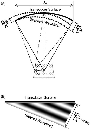
The number of elements which this compromise requires for a typical focused transducer with a geometric focus can be estimated by viewing the schematics in . When the focus is steered by a distance ξ as shown in , the number of wavelengths transmitted from the aperture at a time in continuous wave transmission is . The Nyquist theorem requires that the minimum number of rows of elements in the steered direction in aperture, N1, should be double, as in Equation Equation27
(27) .
(27)
When ξ is set approximately equal to the axial length of the focal region, i.e.
, from Equation Equation8
(8) we get Equation Equation28
(28) .
(28)
Figure 2. Steering focus of array transducer for thermal treatment. (A) Steering angle needed for lateral broadening of heat deposition pattern. (B) Number of waves transmitted at a time by array transducer.
The required number of elements in an aperture is then estimated as in Equation Equation29(29) .
(29)
For a transducer with a unity F-number, , which is a reasonable number of array elements to put into practice. Such an array configuration of the transducer is also useful for axial electronic scanning of the focus at the same time.
The width of a fully populated element of such an array transducer can be estimated from Equation Equation28(28) as in Equation Equation30
(30) .
(30)
For a typical transducer for thermal treatment, it is estimated as Equation Equation31(31) using Equation Equation9
(9) .
(31)
Since the wavelength in PZT is nearly three times that of water, this width corresponds to approximately twice the wavelength in the piezoelectric material. If a transducer element with such a width is simply chosen, one must handle the complicated coupled modes of the element, because its aspect ratio, the width by the thickness, falls into the range of 1–10.
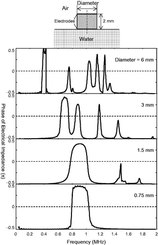
Finite element simulation using PZFlex was performed to analyse the coupled modes for a cylindrical model of a piezoelectric disc with no matching layer as shown in the schematic in . The 2-mm thick air-backed disc consisted of PZT-4. The simulated phase of the electrical impedance is plotted in the figure for widths approximately 4, 2, 1, and 1/2 times the wavelength in water. At widths 4 and 2 times λ, a number of coupled modes are seen in each plot. At widths 1 and 1/2 times λ, the thickness mode is seen uncoupled, and at a half λ, no other modes are seen.
Figure 3. Electrical impedance of air-backed piezoceramic disc-shaped transducer element.
For a typical imaging transducer working in a pulse mode, a coupled mode must be avoided in the frequency bandwidth of the pulse. For a therapeutic transducer for thermal treatment working in CW mode, it is not impossible to use, but special care is needed to intentionally use a coupled mode to generate wanted ultrasound. Therefore, an element width causing coupled modes is normally avoided. An alternative common practice is to choose a relatively small element size causing no coupled mode and electrically combining multiple neighbouring elements to form a relatively large array element. A 1–3 composite transducer [Citation4,Citation20] is such a solution.
Piezocomposite transducer
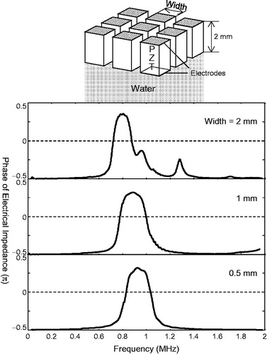
Finite element simulation using PZFlex was also performed for a 1–3 piezocomposite model with no matching layer as shown in the schematic in . The 2-mm thick air-backed model consisted of PZT-4 with a volume content of 50% and kerf filler, which has a density of 1000 kg/m3 and longitudinal and shear velocity of 2000 and 1000 m/s, respectively. The simulated phase of the electrical impedance is plotted in the figure for PZT pillar widths of 1, 1/2, and 1/4 times the thickness. At a width equal to the thickness, i.e. for a cubic pillar, a coupled mode is seen in the plot, but at widths of 1/2, and 1/4 times the thickness, only the thickness mode is seen with no coupled mode. At a pillar width of 1/4 times the thickness, the centre-to-centre distance between neighbouring pillars is approximately half a wavelength in water.
Figure 4. Electrical impedance of air-backed piezocomposite transducer element.
By choosing the centre-to-centre distance between neighbouring pillars less than half a wavelength in water, a piezocomposite array transducer with geometric focus can be matched to the required focus steering ability by modifying the pattern of the electrodes which electrically combine multiple neighbouring pillars. This configuration of focused array transducer has become popular for therapeutic purposes.
The negative side of the composite therapeutic transducer is its limited thermal and mechanical robustness. The mechanical loss in the kerf filler, consisting of a polymer material, leads to temperature rise in the whole composite. This might further trigger catastrophic thermal destruction of the transducer because the mechanical loss of the polymer increases even more as the temperature rises. The air-backed composite is mechanically sustained only by the matching layer in front of it; therefore, it is significantly more mechanically fragile than a single element ceramic transducer.
Conclusion
The guiding principles and considerations for designing typical focused transducers for thermal treatment were reviewed in this paper. The characteristic of an air-backed piezoelectric transducer with a matching layer was analysed, and the role and choice of the matching layer, which is significantly different from a typical imaging transducer working in a pulse mode, was discussed. Assuming that the volume of the target tissue to be treated is much larger than that of the ultrasonic focal spot, the practically appropriate element size of a focused array transducer as well as the optimal ultrasonic frequency was estimated. The characteristic of a piezoceramic transducer element of such a size was numerically analysed using a finite element code. A piezocomposite transducer element was also numerically analysed and proven to have characteristics suitable for such a therapeutic array transducer.
Declaration of interest
The author reports no conflicts of interest. The author alone is responsible for the content and writing of the paper.
References
- Foster RS, Bihrle R, Sanghvi N, Fry F, Kopecky K, Regan J, et al. Production of prostatic lesions in canines using transrectally administered high-intensity focused ultrasound. Eur Urol 1993;23:330–6
- Gelet A, Chapelon JY, Margonari J, Theillere Y, Gorry F, Souchon R, Bouvier R. High-intensity focused ultrasound experimentation on human benign prostatic hypertrophy. Eur Urol 1993;23:44–7
- Uchida T, Sanghvi NT, Gardner TA, Koch MO, Ishii D, Minei S, et al. Transrectal high-intensity focused ultrasound for treatment of patients with stage T1b-2NOMO localized prostate cancer: A preliminary report. Urology 2002;59:394–8
- Daum DR, Hynynen K. A 256-element ultrasonic phased array system for the treatment of large volumes of deep seated tissue. IEEE Trans UFFC 1999;46:1254–68
- Funaki K, Fukunishi H, Funaki T, Kawakami C. Mid-term outcome of magnetic resonance-guided focused ultrasound surgery for uterine myomas: From six to twelve months after volume reduction. J Minim Invasive Gynecol 2007;14:616–21
- Hynynen K, Watmough DJ, Mallard JR. Design of ultrasonic transducers for local hyperthermia. Ultrasound Med Biol 1981;7:397–402
- Ocheltree KB, Benkerser PJ, Frizzell LA, Cain CA. An ultrasonic phased-array applicator for hyperthermia. IEEE Trans Son Ultrason 1984;31:526–31
- Cain CA, Umemura S. Concentric-ring and sector-vortex phased-array applicators for ultrasound hyperthermia. IEEE Trans Microw Theory Tech 1986;34:542–51
- Umemura S, Cain CA. Analysis of temperature responses to diffused ultrasound focal fields produced by a sector vortex phased-array. Int J Hyperthermia 1990;6:641–54
- Cline HE, Hynynen K, Watkins RD, Adams WJ, Schenck JF, Ettinger RH, et al. Focused US system for MR imaging-guided tumor ablation. Radiology 1995;194:731–7
- Rivens IH, Clarke RL, ter Haar GR. Design of focused ultrasound surgery transducers. IEEE Trans UFFC 1996;43:1023–31
- Lweesy K, Fraiwan L, Al-Bataineh O, Hamdi N, Dickhaus H. Optimization of ultrasound array designs for high intensity focused treatment of prostate cancer and benign prostatic hyperplasia. Med Biol Eng Comput 2009;47:635–40
- Hill CR. Optimum acoustic frequency for focused ultrasound surgery. Ultrasound Med Biol 1994;20:271–7
- Ergun AS. Analytical and numerical calculations of optimum design frequency for focused ultrasound therapy and acoustic radiation force. Ultrasonics 2011;51:786–94
- Parker KJ. Ultrasonic attenuation and absorption in liver tissue. Ultrasound Med Biol 1983;9:363–9
- Clement GT, Sun J, Giesecke T, Hynynen K. A hemisphere array for non-invasive ultrasound brain therapy and surgery. Phys Med Biol 2000;45:3707–19
- Ristic VM. Principles of acoustic devices. New York: Wiley; 1983
- Persson HW, Hertz CH. Acoustic-impedance matching of medical ultrasound transducers. Ultrasonics 1985;23:83–9
- De Jong N, Souquet J, Faber G, Bom N. Transducers in medical ultrasound: Vibration modes, matching layers and grating lobes. Ultrasonics 1985;23:176–82
- Smith WA, Auld BA. Modeling 1–3 composite piezoelectrics – thickness-mode oscillations. IEEE Trans Ultrason Ferroelectr Freq Control 1991;38:40–5