
Abstract
Purpose: Currently available microwave hyperthermia systems for breast cancer treatment do not conform to the intact breast and provide limited control of heating patterns, thereby hindering an effective treatment. A compact patch antenna with a flared groundplane that may be integrated within a wearable hyperthermia system for the treatment of the intact breast disease is proposed.
Materials and methods: A 3D simulation-based approach was employed to optimise the antenna design with the objective of maximising the hyperthermia treatment volume (41 °C iso-therm) while maintaining good impedance matching. The optimised antenna design was fabricated and experimentally evaluated with ex vivo tissue measurements.
Results: The optimised compact antenna yielded a −10 dB bandwidth of 90 MHz centred at 915 MHz, and was capable of creating hyperthermia treatment volumes up to 14.4 cm3 (31 mm × 28 mm × 32 mm) with an input power of 15 W. Experimentally measured reflection coefficient and transient temperature profiles were in good agreement with simulated profiles. Variations of + 50% in blood perfusion yielded variations in the treatment volume up to 11.5%. When compared to an antenna with a similar patch element employing a conventional rectangular groundplane, the antenna with flared groundplane afforded 22.3% reduction in required power levels to reach the same temperature, and yielded 2.4 times larger treatment volumes.
Conclusion: The proposed patch antenna with a flared groundplane may be integrated within a wearable applicator for hyperthermia treatment of intact breast targets and has the potential to improve efficiency, increase patient comfort, and ultimately clinical outcomes.
Introduction
Breast cancer is the most frequent cancer among women and comprises around 29% of all female cancers [Citation1]. Early detection and adequate treatment are crucial in the control of the disease [Citation2] and with an improved and extensive use of screening techniques, small carcinomas can be detected, and treated with minimally invasive and non-invasive therapies. Surgical resection (lumpectomy) is the gold standard for treatment of many breast tumours; chemotherapy and radiation therapy are also clinically used [Citation3]. Clinical trials have demonstrated the benefit of adding hyperthermia, moderate heating in the range of 41 °C < T < 45 °C for 30-60 min, as an adjuvant to radiation and/or chemotherapy of tumours in several sites, including breast cancer recurrence to the chest wall [Citation4–7]. Therapeutic effects of hyperthermia include: some direct cytotoxicity due to heating, tumour radiosensitisation and chemosensitisation [Citation8], and stimulation of a mild anti-tumour immune response. Energy sources that have been investigated for delivering hyperthermia with non-invasive applicators include capacitive [Citation9] and inductive [Citation10] radiofrequency devices, microwave antennas [Citation11] and focused ultrasound. The clinical treatment goal is to raise the targeted tumour temperature to 41–45 °C and deliver thermal doses of 6–10 min at 43 °C for 90% of the measured points (CEM43T90) [Citation4,Citation12].
Applicators incorporating a variety of modalities have been developed for treatment of locally advanced breast cancer. Microwave hyperthermia technology (waveguide applicators operating at 915 MHz and 2.45 GHz) has been employed in clinical trials of breast cancer recurrences to the chest wall adjuvant to radiation therapy [Citation13,Citation14]. These trials indicated significant correlation between tumour depth and complete response rate; tumours located at depths more than 2 cm from the skin yielded poor results [Citation13]. Furthermore, drawbacks of these waveguides are their large dimensions, weight, comfort level, limited adaptability for individual patient treatments, and the limited spatial control of energy deposition [Citation15,Citation16]. Other methods for delivering microwave hyperthermia to the intact breast have been explored, including a deformable mirror approach [Citation17] and a metamaterial microwave lens [Citation18] to focus energy within tumours. Fenn et al. [Citation19] developed an approach for focused microwave hyperthermia involving multiple waveguides compressing the targeted breast. Stang et al. have developed a rigid cylindrical array of patch antennas for non-invasive high-temperature thermal therapy and imaging of breast targets [Citation20]. Ultra-wideband strategies for non-invasive delivery of microwave hyperthermia have also been explored [Citation21].
While ultrasound energy offers the advantage of deep penetration depth, the short acoustic wavelength within soft tissue results in small focal spots. Since hyperthermia treatments require moderate heating of large volumes, techniques for scanning the focal spot over the treatment volume are typically employed [Citation22–24]. Guo and Li [Citation25] proposed a waveform diversity technique for hyperthermia, demonstrating feasibility of effective heating of a 16-mm diameter tumour centred 10 mm beneath the skin surface. Bakker et al. [Citation26] conducted a computational investigation of a low frequency (∼100 kHz) ultrasound array for hyperthermia treatment of tumours within intact breast. Their study indicated the feasibility of treating deep-seated tumours (∼4–9 cm from the skin surface) with an applicator consisting of six rings with 32 transducers per ring. Ultrasound applicators have been designed and clinically employed for simultaneously delivering hyperthermia and ionising radiation to large regions of the chest for treatment of recurrent disease [Citation27]. The small focal spots feasible with ultrasound energy are well suited to high temperature focused ultrasound surgery of breast tumours [Citation28].
Although the approaches summarised above facilitate delivery of hyperthermia to deep-seated targets, they generally require horizontal patient positioning with the breast vertically suspended within a cavity. An ergonomically shaped and wearable system in close proximity to the breast would offer enhanced energy deposition, reduced power requirements, and increased comfort, which would facilitate treatment delivery, improve therapeutic adherence and patient treatment persistence [Citation29]. Stauffer et al. [Citation30] developed a conformal array of microstrip antennas for hyperthermia treatment of large surfaces with superficial chest wall disease (<20 mm depth). Compared to waveguide technologies, this approach significantly improves patient comfort and provides enhanced control of power deposition patterns over large treatment areas. However, these applicators are not well suited to treatment of disease within intact breast. Requirements of antenna designs for non-invasive hyperthermia include good impedance matching and bandwidth, generation of predominantly tangential electric fields, small size, and ability to conform to the targeted anatomy. Furthermore, for wearable devices, there is an additional requirement that electromagnetic interaction (EMI) remains within prescribed safety limits. Several antenna designs have been considered for non-invasive hyperthermia, including patch [Citation31], spiral [Citation32], dipoles [Citation33,Citation34], and others. Benefits of patch antennas include the simple design, good impedance matching, and ability to generate tangential electric fields. They have been extensively characterised and utilised for treatment of tumours in the head and neck [Citation35,Citation36].
The objective of this study was to design and characterise the electromagnetic and heating performance of a novel 915 MHz patch antenna with a flared conical groundplane for integration within a wearable breast hyperthermia system. The optimised antenna design yields good impedance matching for antenna positions in close proximity (5 mm) to the breast, does not require a feed-line matching network, yields large treatment volumes that are robust to relatively large changes in blood perfusion, and offers significantly reduced power requirements and leakage radiation.
Materials and methods
Design objectives
Our long-term objective is to develop a microwave hyperthermia system that integrates into a brassiere cup (or other garment) to increase comfort during the clinical session. The applicator needs to be light and compact, both in profile, and cross-section, and the system needs to be robust to maintain electromagnetic energy focused on the targeted tumour while tolerating small patient movements during clinical hyperthermia treatments. The applicator should be located close to the skin to minimise power loss in the water bolus. Changing loading conditions encountered in different patients can compromise the system stability. These conditions include varying skin thickness, tumour composition, variable antenna to skin distances, and patient postural changes. These variations are equivalent to changes in the effective wavelength of the target, with the consequent system variation in frequency response. Large matched impedance bandwidth is therefore desirable to enhance the overall system stability. The applicator should present tangentially aligned E-fields to improve energy deposition into the breast tissue, avoid hot spots in the skin, and to reduce the power required to couple energy into the tumour volume [Citation31,Citation37]. Avoiding the use of impedance matching circuits increases system efficiency and simplifies clinical integration.
Antenna geometry
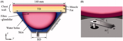
shows the proposed antenna which comprises a rectangular patch of length L, and width W, and a flared groundplane. The flared groundplane has a conical geometry parameterised by the base diameter BD, and top diameter TD. The patch is centrally aligned with the ground-plane base, and positioned at a distance h1. The antenna feed is centred with respect to W, and at a distance Lo from the patch edge. The water bolus formed all the cavity enclosed by the flared groundplane, breast and chest wall. Dionised water completely filling the water bolus was used to improve the matched impedance, reduce the size of the applicator, and cool both the antenna and surface of the skin.
Figure 1. Two-dimensional view of the proposed antenna with flared groundplane and breast model (A), and 3D zoomed view of the patch element (B) with the parametrised dimensions.
Numerical breast phantom
A coupled 3D electromagnetic bioheat transfer finite element method (FEM) model was implemented to characterise the performance of candidate antenna designs. The Helmholtz wave equation was solved to determine the electromagnetic fields deposited in the tissue by the prototype applicator. The Pennes bioheat equation was used to compute the temperature profile in the tissue [Citation38].
(1)
where ρ is the material density (kg m−3), C is the specific heat capacity (J kg−1 C−1), T is the variable quantity of temperature (°C) at a time t (s), k is the thermal conductivity (W m−1 °C−1), Q is the heat source or volumetric power deposition (W m−3), B is the blood perfusion coefficient (W m−3°C−1), Tbl is the blood temperature (°C), and A0 is the heat generated by metabolism (W m−3). A steady-state formulation of the Pennes equation (i.e.
, which is suitable for long-duration (30–60 min) hyperthermia treatments [Citation39] was employed for simulations during the design/optimisation phase. The transient version of Equation 1 was employed when comparing experimentally observed temperature profiles with simulations. The heat source in the Pennes equation was calculated from the electromagnetic fields using Equation 2
(2)
where J is the current density (A m−2), and E is the electric field intensity (V m−1). To minimise computational resources and for clarity of the results, a hemispheric two-layer numerical breast phantom was used. The breast phantom had an outer diameter of 90 mm and comprised a 2-mm thick skin layer encompassing fibroglandular tissue [Citation40]. The chest wall, modelled as a 140 mm × 140 mm layer of 15-mm thick fat adjacent to 5-mm thick muscle (with the same thermal properties as fibroglandular tissue as in [Citation41] and dielectric properties as in [Citation42]), terminated the top wall of the breast phantom, as shown in . The temperature of the water was kept constant at 20 °C. Frequency dependent dielectric and thermal properties for water, skin, fibroglandular and fat tissue were implemented in the model, as listed in .
Table 1. Tissue dielectric and thermal properties for 915 MHz.
Perfect electric conductor boundary conditions were applied on all copper surfaces. Scattering boundary conditions were applied at the edges of the outer walls of the chest to minimise reflections at model boundaries. A fixed temperature boundary condition (T = 20 °C) was applied at the water–skin interface to approximate the cooling effects of circulating water. Temperature at extents of the chest wall was set to 37 °C to mimic actual body temperature. The model was discretised using a non-uniform mesh of tetrahedral elements. The antenna feed was modelled with the finest meshing, maximum edge length of 0.1 mm, and the coarsest elements were employed further away from the antenna with a maximum element edge length of 3.0 mm. This mesh resolution was determined following iterative adjustments to satisfy a Cauchy convergence test on the S11. Electromagnetic and thermal simulations were performed using COMSOL Multiphysics (Burlington, MA) on a 24-core workstation, with 64 GB RAM, running Red Hat Linux.
Evaluation of antenna designs
The key performance criteria of a microwave hyperthermia applicator are 1) the efficient transfer of energy into the targeted tissue, and 2) the induced tissue temperature profile (treatment volume and uniformity of heating). The parametrised dimensions (W, L, Lo, h1, h2, BD, and TD) of the proposed applicator () were optimised with the aim of large treatment volume and antenna matched impedance (S11∼−30 dB). The extent of the hyperthermia treatment volume was approximated with the 41 °C iso-therm [Citation39]. After the optimum values were obtained, a sensitivity analysis was performed to evaluate the impact of small variations of individual geometric parameters.
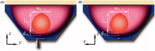
In order to compare the performance of the proposed antenna design, a second antenna with a rectangular groundplane (i.e. conventional patch antenna) was evaluated. The optimisation parameters of this second antenna were the width and length of the rectangular groundplane being able to fit in the base of the flared groundplane. All the other antenna and water bolus dimensions were the same as in the proposed antenna. The optimisation goal was to minimise the S11 at 915 MHz. shows a 3D schematic representation of the proposed antenna with flared groundplane and the antenna with rectangular groundplane. The E-field profile generated by each antenna was evaluated to identify potential hot-spots and assess the electric field radiated outside the targeted tissue. For thermal models, the following thermal parameters were employed to characterise the treatment zone when considering a nominal input power of 15 W: maximum tissue temperature, distance from the skin to the treatment volume d41, width of the treatment volume in the plane yz w41_yz, width of the treatment volume in the plane xz w41_xz, and length of the treatment volume l41, as shown in . Additionally, extents of the treatment volume were also quantified with input power adjusted to achieve a maximum tissue temperature of 46 °C. To characterise the robustness of the proposed antenna, ± 50% variation in blood perfusion within the glandular tissue [Citation39–45] were evaluated.
Figure 2. Schematic representation of the antenna with flared groundplane (A) and with rectangular groundplane (B).
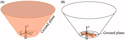
Figure 3. Schematic representation of the breast comprising the treatment volume (41 °C iso-therm volume), distance from the skin to the treatment volume, d41, width of the treatment volume in the plane yz, w41_yz, width of the treatment volume in the plane xz, w41_xz, and length of the treatment volume l41.
Experimental evaluation and validation against simulations
The proposed antenna with flared groundplane was fabricated, employing optimised antenna dimensions identified from simulations. The patch and groundplane were implemented with 0.127-mm thick copper sheets (McMaster-Carr, Elmhurst, IL). A 50 Ω SMA female connector (PE4099, Pasternack Enterprise, Irvine, CA) was used to feed the antenna. The broadband reflection coefficient of the fabricated antenna was measured when in proximity to a tissue phantom of ex vivo chicken breast. Heating experiments in the tissue phantom were performed with the set-up illustrated in to measure the transient temperature profiles induced by the proposed applicator. Chicken breast samples were heated to ∼32 °C in a temperature controlled bath before performing the heating experiments and then positioned in a 1.5-mm thick PTFE fixture. Fibre-optic temperature probes (Neoptix RFX-04-1, Qualitrol, Fairport, NY) guided with a PTFE template were placed within the tissue sample as shown in . Room temperature water was circulated through the system at a flow rate of 5 mL/s with a peristaltic pump (Cole-Parmer, 7554-90, Vernon Hills, IL). Applied input power was initially set at 20 W during the first 2 min and then reduced to 8 W for the following 8 min. These power levels were employed to mimic a ramp up to target temperature, followed by maintenance within the hyperthermic temperature range. Heating experiments were performed in quadruplicate.
Figure 4. Set-up for experimental assessment of antennas in ex vivo tissue.
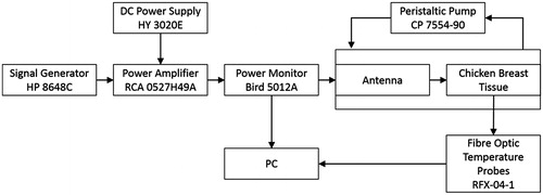
Figure 5. Schematic representation of the antenna set-up measurement.
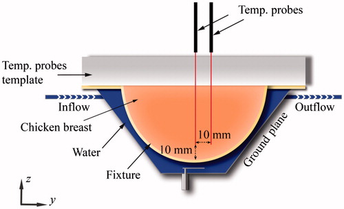
To facilitate a fair comparison of experimental measurements against simulations, an additional computational model closely mimicking the experimental set-up was implemented (see ). This model employed dielectric properties of the PTFE of fixture and temperature template as in Arunachalam et al. [Citation46], and chicken breast phantom measured with an Agilent 85070D (Santa Clara, CA) open-ended coaxial dielectric probe kit. The measured values (εr = 57.75 and σ = 1.49 S/m) were in good agreement with values reported in the literature [Citation47]. In these simulations we employed thermal properties of muscle; the initial phantom temperature was set to 32 °C, and a fixed temperature boundary condition (T = 25 °C) was applied at water–fixture interference to approximate the cooling effects of the circulating water.
Results
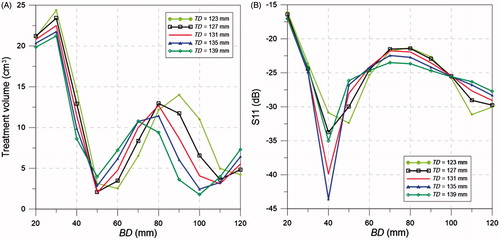
The optimal antenna dimensions, offering a balance between large treatment volume and S11 less than −30 dB (i.e. < 0.1% reflected power), were W = 3.9 mm, L = 13.7 mm, h1 = 3.3 mm, Lo = 0.25 mm, h2 = 5 mm, BD = 40 mm and TD = 123 mm. illustrates how the dimensions of the flared groundplane impacts the treatment volume and S11 at 915 MHz, when considering an input power of 15 W.
Figure 6. Treatment volume (A) and S11 (B) for different cone base diameter (BD) and top diameter (TD).
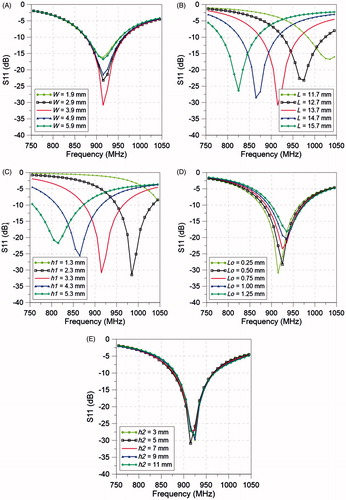
The impact of the antenna dimensions, patch width, W, patch length, L, groundplane to patch distance, h1, feed offset, Lo, and distance patch to skin, h2, on the antenna matched impedance (S11) was evaluated and it is illustrated in .
Figure 7. Simulated S11 of the antenna with flared groundplane for different values of (A) W, (B) L, (C) h1, (D) Lo, and (E) h2.
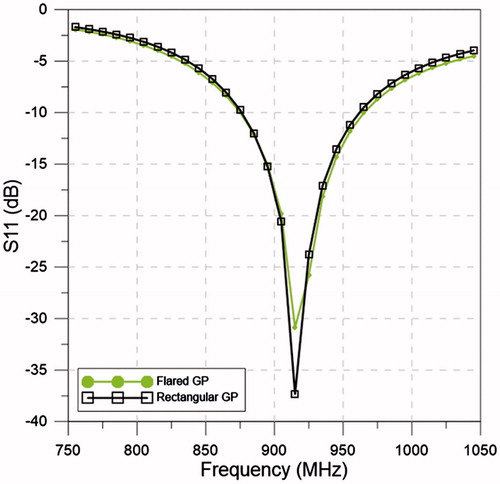
shows the simulated S11 values for the flared and rectangular ground-plane antennas with their optimised dimensions. The optimised dimensions of the rectangular groundplane were 32.5 mm × 17.0 mm, which represented a conventional groundplane yielding a resonant frequency at 915 MHz. Simulations show a good agreement with resonant frequencies centred at 915 MHz and −10 dB bandwidth of 90 MHz for the flared ground-plane antenna and 85 MHz for the rectangular ground-plane antenna.
Figure 8. Simulated S11 of the antennas with flared and rectangular groundplane with the optimised dimensions of W, L, h1, Lo, h2, BD and TD.
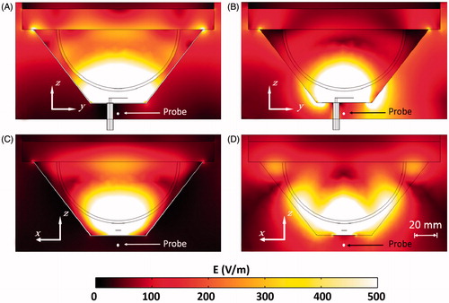
The E-field cross-section on the planes -yz and -xz of the flared and rectangular ground-plane antenna with an input power of 15 W are shown in . In order to quantify the E-field leakage on the back of the antenna, the E-field was evaluated at a point centred with the groundplane and at a distance of 10 mm, as shown in . The simulated E-field at that location was 25.8 V m−1 and 136.6 V m−1 for the flared and rectangular ground-plane antenna, respectively.
Figure 9. E-field profile for the flared groundplane antenna plane yz (A) and xz (C) and rectangular ground-plane antenna plane yz (B) and xz (D), with 15 W input power.
shows the temperature cross-section on the planes -yz and -xz of the flared and rectangular ground-plane antenna with an input power of 15 W. At this power level, treatment volumes and maximum tissue temperatures for the flared ground-plane antenna were 14.4 cm3 and 47.3 °C, respectively, and for the rectangular ground-plane antenna were 1.48 cm3 and 42.9 °C, respectively. Additional simulations were performed with input power for both antenna designs adjusted to limit maximum tissue temperature to 46 °C. The required input power for a maximum temperature of 46 °C was 13.9 W for the flared groundplane and 17.9 W for the rectangular ground-plane antenna. lists input power and evaluated thermal parameters for both the flared and rectangular ground-plane antennas.
Figure 10. Temperature profile for the flared ground-plane antenna plane yz (A) and xz (C) and rectangular ground-plane antenna plane yz (B) and xz (D), with 15 W input power.
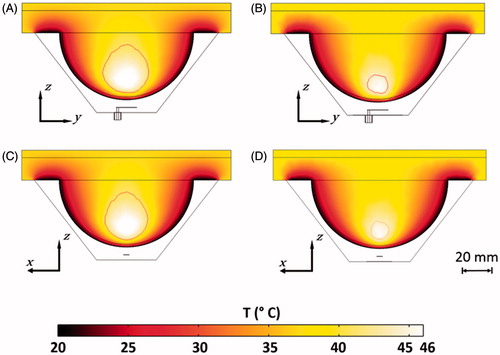
Table 2. Treatment volume outcomes.
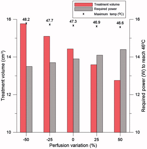
illustrates the treatment volume, maximum tissue temperature with an input power of 15 W, and required power to reach 46 °C for ± 50% variation in the blood perfusion coefficient in the glandular tissue for the antenna with flared groundplane. Increasing the blood perfusion by +50% generates a linear decrease of around 11.5% in the treatment volume and 1.5% in the maximum temperature. The power required to reach 46 °C increased by 3.6% for this 50% blood perfusion increment. With 50% increase in the perfusion, the flared ground-plane antenna still renders a treatment volume 8.6 times larger than the rectangular ground-plane antenna without any increase in the perfusion considering same input power.
Figure 11. Treatment volume, maximum temperature with 15 W input power (symbolised with ×), and required power to reach 46 °C for different perfusion values for the proposed antenna with flared groundplane.
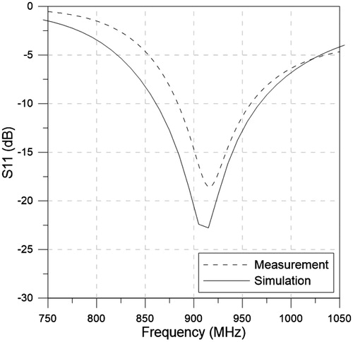
shows the experimentally measured and simulated broadband reflection coefficient with the ex vivo tissue phantom (employing parameters mimicking the experimental set-up).
Figure 12. Simulated and measured S11 with the ex vivo tissue phantom.
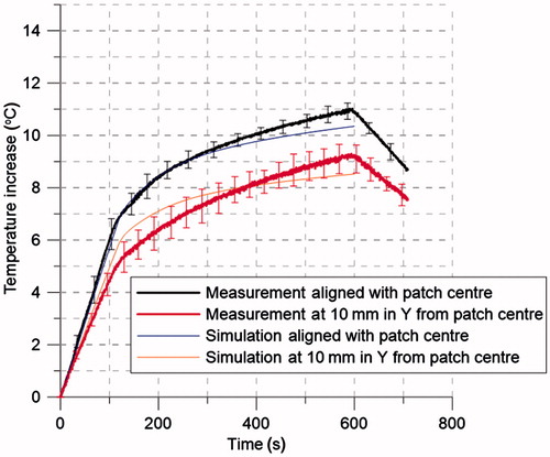
shows experimentally measured (n = 4) and simulated transient temperature profiles during heating experiments performed in chicken breast, while manually adjusting power (20 W for 2 min, followed by 8 W for 8 min) to allow for a rapid temperature rise, followed by maintenance of hyperthermic temperature.
Figure 13. Transient temperature profiles (n = 4) measured during experimental ex vivo hyperthermia treatment. Two fibre-optic temperature probes were placed at a depth of 10 mm from the tissue surface, and at the locations shown in . Input power was set to 20 W for the first 2 min followed by 8 W for the following 8 min.
Discussion
This study was initiated to design and evaluate the feasibility of a wearable breast hyperthermia system. A lightweight and wearable system would avoid uncomfortable breast compression and follow patient breathing and motion, allowing patient postural changes during the treatment, thereby improving comfort [Citation30], facilitating treatment persistency, and therapeutic adherence [Citation29]. The wearable device may contribute towards delivering hyperthermia treatments in a repeatable manner over the course of several radiation and/or chemotherapy fractions. A patch antenna design was considered for this study because it presents the advantages of being light, does not require a feed-line matching network, can be constructed with an ergonomic shape, and can generate tangential electric fields.
Simulations were employed to optimise the dimensions of the antenna and assess its robustness. The ground-plane dimensions were found to have a significant effect on the power deposition and matched impedance. With the aim of getting the largest possible treatment volume while keeping a matched impedance close to −30 dB, the optimum values of BD and TD were found to be 40 mm and 123 mm, respectively (). If the system allows the compromising of the amount of reflected power, greater treatment volumes can be achieved. A sensitivity analysis of the antenna dimensions and distance to the skin was performed (). Changes on the patch width, W, and feed offset, Lo, did not generate a noticeable change in the resonant frequency, considering variations up to ±50%, S11 at 915 MHz remained less than −15 dB. However, the matched impedance was more sensitive to the patch length, L, and groundplane to patch distance, h1; variations of ± 10% would degrade the S11 at 915 MHz to values greater than −10 dB. The evaluated increases of L and h1 rendered an almost linear decrease in resonant frequency. Previous studies have indicated that a water bolus layer of between 5 mm and 10 mm thick was found to be optimum to avoid hot spots in the surface of treated tissue [Citation48,Citation49]. In this study, the water bolus filled the entire cavity between the groundplane, the breast and chest wall. While the groundplane was kept in contact with the chest wall, the breast was placed at different distances from the patch. Patch antenna to skin distances (h2) ranging between 3 mm and 11 mm were evaluated. These variations did not generate a noticeable change in the resonant frequency and the optimum S11 was found at h2 of 5 mm. Locating the applicator in close proximity to the breast considerably increases the antenna efficiency and reduces the required transmitted power, simplifying the power amplifier requirements. Simulations demonstrated that the flared and rectangular ground-plane antennas had similar impedance matching profiles (see ).
The flared ground-plane antenna yielded an E-field distribution confined within the groundplane and focused into the tissue with a defined central hotspot, whereas significant E-field is radiated away from the tissue for the rectangular ground-plane design, which generates a diffuse hotspot inside the tissue. An evaluation of the E-field centred with the groundplane and at a distance of 10 mm shows the back-radiation reduced by 81.1% for the flared groundplane compared to the rectangular ground-plane antenna. Minimising the leakage E-field is desirable to avoid undesirable interference with other medical devices. Power deposited in the fibroglandular tissue region, compared to total power loss (i.e. power deposited in skin, fibroglandular tissue, and water) was 0.45 for the flared ground-plane antenna, and 0.31 for the rectangular ground-plane antenna. Considering the same input power for the flared and rectangular ground-plane antenna (15 W), the flared ground-plane antenna achieves 9.7 times larger treatment volumes. Taking into account the power required to reach 46 °C, the flared ground-plane antenna requires 22.3% less power (i.e. increase in efficiency) and still yields 2.4 times larger treatment volumes. In addition to these outcomes, and considering the adjusted power to reach 46 °C, the flared ground-plane antenna provides enhanced penetration, affording 45.5% increase in treatment depth (l41 increased from 16.83 mm for the rectangular patch to 27.4 mm for the flared ground-plane). Also, wyz_41 and wxz_41 increased around 38.2% and 43% respectively for the flared ground-plane antenna. The power reduction ability of the flared ground-plane antenna affords an increase of the distance from the skin to the treatment volume d41 of 31.4% compared to the rectangular ground-plane antenna. To assess the impact of variable blood perfusion on treatment outcome, perfusion in the glandular tissue was varied by ± 50% from the basal value for the antenna with flared groundplane. Model-predicted treatment volume remained stable over the range of simulated perfusion values, suggesting that the optimised flared patch antenna design will be capable of delivering reliable hyperthermia treatments in patients with disparate blood flow profiles. It provides a starting point for power selection based on the perfusion values for individual patients; clinical treatments will incorporate temperature-based feedback control algorithms for reliable delivery of hyperthermia to targeted volumes [Citation50].
Measured reflection coefficient in ex vivo chicken breast was in good agreement with simulations, showing resonance at 915 MHz and an average difference between measurement and simulations of 1.8 dB on the evaluated frequency range. The measured temperature profiles (see ) illustrate the ability of the proposed antenna design to heat targets within the breast when applying relatively low input power levels under manual control (8–20 W). Measured temperature profiles were in good agreement with simulations.
In this study we have employed computational and experimental approaches to design and characterise a patch antenna element with a flared groundplane for microwave hyperthermia of breast targets. Compared to a conventional patch antenna employing a rectangular groundplane the proposed system has reduced power requirements, generates substantially reduced E-field outside the targeted breast, and is capable of treating larger treatment volumes to greater depths. This initial study, focused towards design of the antenna element, did not incorporate dielectric and thermal heterogeneities between the targeted tumour and background breast tissues. Similar to other studies of microwave hyperthermia, we hypothesise that dielectric contrast between tumour and background tissue will enable greater heating of the target with respect to non-targeted regions [Citation44]. Future studies will incorporate detailed anatomical features as informed by patient-specific images to illustrate potential clinical applications of the proposed design. Ongoing studies are investigating potential for implementing conformal patch antenna designs with conductive-ink printers on thin, flexible substrates to facilitate integration within hyperthermia garments [Citation51]. While this study focused on the performance of the antenna with a single radiating element, future work investigating how multiple antennas can be integrated within the system (i.e. number of elements, inter-element spacing, antenna excitation parameters) to afford improved focusing and coverage of larger treatment volumes at greater depths is warranted.
Conclusion
Design, optimisation, and evaluation of a novel compact antenna with flared groundplane for integration within a wearable platform for delivering microwave hyperthermia treatments of breast cancer was presented. The proposed design provides good matched impedance at 915 MHz, does not require the use of a feed-line matching network, and facilitates treatment volumes up to 14.43 cm3 with an input power of 15 W. Compared to evaluated patch antenna designs incorporating a conventional rectangular groundplane, the proposed conformal design yields significantly larger treatment volume and reduction in power required. Computational models indicate the size of treatment volume is relatively stable when considering up to ±50% changes in tissue blood perfusion, making it well suited for treatment of patients with disparate blood perfusion profiles. The reduced size of the patch element (13.7 mm × 3.9 mm) would facilitate the potential for future efforts towards integration of multiple antenna elements within a wearable system. Furthermore, the proposed wearable design has profile, weight and complexity advantages over currently available large waveguides and rigid antenna arrays. This wearable device has the potential to significantly improve clinical delivery of conformal hyperthermia and patient comfort during treatments.
Declaration of interest
This work was supported in part by the National Science Foundation under grant CBET 1337438 and in part by the Johnson Cancer Research Center of the Kansas State University. The authors alone are responsible for the content and writing of the paper.
References
- Siegel R, Naishadham D, Jemal A. Cancer statistics, 2013. CA Cancer J Clin 2013 63:11–30
- Cancer.org. Cancer prevention & early detection Facts & figures 2013. Atlanta, GA: American Cancer Society, 2013. Available from http://www.cancer.org/research/cancerfactsfigures/cancerpreventionearlydetectionfactsfigures/ (accessed 18 March 2015)
- Cancer.org. Detailed guide: Breast cancer. Atlanta, GA: American Cancer Society, 2014. Available from http://www.cancer.org/cancer/breastcancer/detailedguide/index (accessed 18 March 2015)
- Jones EL, Oleson JR, Prosnitz LR, Samulski TV, Vujaskovic Z, Yu D, et al. Randomized trial of hyperthermia and radiation for superficial tumors. J Clin Oncol 2005;23:3079–85
- Franckena M, Lutgens LC, Koper PC, Kleynen CE, van der Steen-Banasik EM, Jobsen JJ, et al. Radiotherapy and hyperthermia for treatment of primary locally advanced cervix cancer: Results in 378 patients. Int J Radiat Oncol Biol Phys 2009;73:242–50
- van der Zee J, Gonzalez Gonzalez D, van Rhoon GC, van Dijk JDP, van Putten WLJ, Hart AAM. Comparison of radiotherapy alone with radiotherapy plus hyperthermia in locally advanced pelvic tumours: A prospective, randomised, multicentre trial. Lancet 2000;355(9210):1119–25
- Sneed PK, Stauffer PR, McDermott MW, Diederich CJ, Lamborn KR, Prados MD, et al. Survival benefit of hyperthermia in a prospective randomized trial of brachytherapy boost ± hyperthermia for glioblastoma multiforme. Int J Radiat Oncol Biol Phys 1998;40:287–95
- Zagar TM, Oleson JR, Vujaskovic Z, Dewhirst MW, Craciunescu OI, Blackwell KL, et al. Hyperthermia combined with radiation therapy for superficial breast cancer and chest wall recurrence: A review of the randomised data. Int J Hyperthermia 2010;26:612–17
- Kroeze H, Van de Kamer JB, De Leeuw AAC, Kikuchi M, Lagendijk JJW. Treatment planning for capacitive regional hyperthermia. Int J Hyperthermia 2003;19:58–73
- Storm FK, Elliott RS, Harrison WH, Morton DL. Clinical RF hyperthermia by magnetic-loop induction: A new approach to human cancer therapy. Microw Theory Tech IEEE Trans On 1982;30:1149–58
- van Rhoon GC. External electromagnetic methods and devices. In: Moros EG, editor. Physics of Thermal Therapy: Fundamentals and Clinical Applications, Boca Raton, FL: CRC Press; 2013, pp. 139–58
- Hand JW, Machin D, Vernon CC, Whaley JB. Analysis of thermal parameters obtained during phase III trials of hyperthermia as an adjunct to radiotherapy in the treatment of breast carcinoma. Int J Hyperthermia 1997;13:343–64
- Vernon CC, Hand JW, Field SB, Machin D, Whaley JB, van der Zee J, et al. Radiotherapy with or without hyperthermia in the treatment of superficial localized breast cancer: Results from five randomized controlled trials. Int J Radiat Oncol Biol Phys 1996;35:731–44
- Sherar MD, Liu FF, Newcombe DJ, Cooper B, Levin W, Taylor WB, et al. Beam shaping for microwave waveguide hyperthermia applicator. Int J Radiat Oncol Biol Phys 1993;25:849–57
- Stauffer PR, Maccarini P, Arunachalam K, Craciunescu O, Diederich C, Juang T, et al. Conformal microwave array (CMA) applicators for hyperthermia of diffuse chest wall recurrence. Int J Hyperthermia 2010;26:686–98
- Diederich CJ, Stauffer PR, Bozzo D. An improved bolus configuration for commercial multielement ultrasound and microwave hyperthermia systems. Med Phys 1994;21:1401–3
- Arunachalam K, Udpa SS, Udpa L. Computational feasibility of deformable mirror microwave hyperthermia technique for localized breast tumors. Int J Hyperthermia 2007;23:577–89
- Wang G, Gong Y. Metamaterial lens applicator for microwave hyperthermia of breast cancer. Int J Hyperthermia 2009;25:434–45
- Fenn AJ, Wolf GL, Fogle RM. An adaptive microwave phased array for targeted heating of deep tumours in intact breast: Animal study results. Int J Hyperthermia 1999;15:45–61
- Stang J, Haynes M, Carson P, Moghaddam M. A preclinical system prototype for focused microwave thermal therapy of the breast. IEEE Trans Biomed Eng 2012;59:2431–8
- Converse M, Bond EJ, Veen BD, Hagness SC. A computational study of ultra-wideband versus narrowband microwave hyperthermia for breast cancer treatment. IEEE Trans Microw Theory Tech. 2006;54:2169–80
- Ho C-S, Ju K-C, Cheng T-Y, Chen Y-Y, Lin W-L. Thermal therapy for breast tumors by using a cylindrical ultrasound phased array with multifocus pattern scanning: A preliminary numerical study. Phys Med Biol 2007;52:4585–99
- Ju K-C, Tseng L-T, Chen Y-Y, Lin W-L. Investigation of a scanned cylindrical ultrasound system for breast hyperthermia. Phys Med Biol 2006;51:539–55
- Lu X-Q, Burdette EC, Svensson GK. Ultrasound field calculation in a water-soft tissue medium. Int J Hyperthermia 1998;14:169–82
- Guo B, Li J. Waveform diversity based ultrasound system for hyperthermia treatment of breast cancer. IEEE Trans Biomed Eng 2008;55:822–6
- Bakker JF, Paulides MM, Obdeijn IM, van Rhoon GC, van Dongen KWA. An ultrasound cylindrical phased array for deep heating in the breast: Theoretical design using heterogeneous models. Phys Med Biol 2009;54:3201–15
- Varma S, Myerson R, Moros E, Taylor M, Straube W, Zoberi I. Simultaneous radiotherapy and superficial hyperthermia for high-risk breast carcinoma: A randomised comparison of treatment sequelae in heated versus non-heated sectors of the chest wall hyperthermia. Int J Hyperthermia 2012;28:583–90
- Kovatcheva R, Guglielmina J-N, Abehsera M, Boulanger L, Laurent N, Poncelet E. Ultrasound-guided high-intensity focused ultrasound treatment of breast fibroadenoma – a multicenter experience. J Ther Ultrasound 2015;3:1–8
- Puts MTE, Tu HA, Tourangeau A, Howell D, Fitch M, Springall E, et al. Factors influencing adherence to cancer treatment in older adults with cancer: A systematic review. Ann Oncol 2014;25:564–77
- Stauffer PR, Maccarini P, Arunachalam K, Craciunescu O, Diederich C, Juang T, et al. Conformal microwave array (CMA) applicators for hyperthermia of diffuse chest wall recurrence. Int J Hyperthermia 2010;26:686–98
- Paulides MM, Bakker JF, Chavannes N, Rhoon GC van. A patch antenna design for application in a phased-array head and neck hyperthermia applicator. IEEE Trans Biomed Eng 2007;54:2057–63
- Johnson JE, Neuman DG, Maccarini PF, Juang T, Stauffer PR, Turner P. Evaluation of a dual-arm Archimedean spiral array for microwave hyperthermia. Int J Hyperthermia 2006;22:475–90
- Wust P, Hildebrandt B, Sreenivasa G, Rau B, Gellermann J, Riess H, et al. Hyperthermia in combined treatment of cancer. Lancet Oncol 2002;3:487–97
- Chen J-Y, Gandhi OP. Numerical simulation of annular-phased arrays of dipoles for hyperthermia of deep-seated tumors. IEEE Trans Biomed Eng 1992;39:209–16
- Paulides MM, Bakker JF, Neufeld E, Zee J van der, Jansen PP, Levendag PC, et al. The HYPERcollar: A novel applicator for hyperthermia in the head and neck. Int J Hyperthermia 2007;23:567–76
- Paulides MM, Bakker JF, Linthorst M, van der Zee J, Rijnen Z, Neufeld E, et al. The clinical feasibility of deep hyperthermia treatment in the head and neck: New challenges for positioning and temperature measurement. Phys Med Biol. 2010;55:2465–80
- Curto S, McEvoy P, Bao X, Ammann MJ. Compact patch antenna for electromagnetic interaction with human tissue at 434 MHz. IEEE Trans Antennas Propag 2009;57:2564–71
- Pennes HH. Analysis of tissue and arterial blood temperatures in the resting human forearm. J Appl Physiol 1948;1:93–122
- Wootton JH, Prakash P, Hsu I-CJ, Diederich CJ. Implant strategies for endocervical and interstitial ultrasound hyperthermia adjunct to HDR brachytherapy for the treatment of cervical cancer. Phys Med Biol 2011;56:3967–84
- Haynes M, Stang J, Moghaddam M. Microwave breast imaging system prototype with integrated numerical characterization. Int J Biomed Imaging 2012;1:1–18
- Zastrow E, Hagness SC, Van Veen BD. 3D computational study of non-invasive patient-specific microwave hyperthermia treatment of breast cancer. Phys Med Biol 2010;55:3611–29
- Gabriel S, Lau RW, Gabriel C. The dielectric properties of biological tissues: III. Parametric models for the dielectric spectrum of tissues. Phys Med Biol 1996;41:2271–93
- Kaatze U. Reference liquids for the calibration of dielectric sensors and measurement instruments. Meas Sci Technol 2007;18:967–76
- Zastrow E, Davis SK, Lazebnik M, Kelcz F, Van Veen BD, Hagness SC. Development of anatomically realistic numerical breast phantoms with accurate dielectric properties for modeling microwave interactions with the human breast. IEEE Trans Biomed Eng 2008;55:2792–800
- De Greef M, Kok HP, Correia D, Borsboom P-P, Bel A, Crezee J. Uncertainty in hyperthermia treatment planning: The need for robust system design. Phys Med Biol 2011;56:3233–50
- Arunachalam K, Maccarini PF, Stauffer PR. A thermal monitoring sheet with low influence from adjacent waterbolus for tissue surface thermometry during clinical hyperthermia. IEEE Trans Biomed Eng 2008;55:2397–406
- Roelvink J, Trabelsi S. Measuring the complex permittivity of poultry meat with a planar transmission-line sensor. IEEE Int I2MTC 2013;2013:1689–93
- Neuman DG, Stauffer PR, Jacobsen S, Rossetto F. SAR pattern perturbations from resonance effects in water bolus layers used with superficial microwave hyperthermia applicators. Int J Hyperthermia 2002;18:180–93
- Gelvich E, Mazokhin V. Resonance effects in applicator water boluses and their influence on SAR distribution patterns. Int J Hyperthermia 2000;16:113–28
- Kowalski ME, Jin JM. A temperature-based feedback control system for electromagnetic phased-array hyperthermia: Theory and simulation. Phys Med Biol 2003;48:633–51
- Curto S, Suh M, Prakash P. Design and analysis of a conformal patch antenna for a wearable breast hyperthermia treatment system. Proc SPIE 2015;9326. doi:10.1117/12.2079718