
Abstract
Purpose: The aim of this study was to design an applicator for haemostasis usage needing lower acoustic intensities (<880 W/cm2) than in previous devices intended for it, which is based on ultrasound propagation FEM modelling using a 2-MHz HIFU transducer. Materials and methods: Acoustic field characterisation and numerical simulations in water were performed with and without the proposed applicator. Parameters such as form factor, ellipsoidal shape ratio, and Euclidean distance were used (among others) to compare simulated data with transducer measurements without applicator. A low density polyethylene cone was manufactured from geometries validated from acoustic field modelling. The hollow cone was filled with 10% polyacrylamide gel as a coupling medium with liver phantom or chicken liver. Focal temperature was measured with a thermocouple embedded in the phantom for 1–20 W driving powers for 120 s. Standing wave ratios (SWR) were used as coupling indexes. Ex vivo experimentation in chicken liver was made at 10–20 W. Results: Simulated acoustic patterns showed good concordance with measurements. Experimental focal distance was 20.72 ± 0.24 mm, while the simulated was 19.79 mm (≈4% error). SWR at low power were: 2.01 with transducer emitting in air, 1.53 at applicator tip, and 1.35 after phantom placement. Average SWR at high power was 1.31. Similarity of percentages for data comparison in focal plane was over 60%. Maximum temperature measured at focus was 88.7 °C with 20 W after 85 s. Conclusions: Temperatures reached at focus suggest that this applicator has good efficiency, which notably reduces the power typically needed for haemostasis effect.
Introduction
High intensity focused ultrasound (HIFU) has been proposed by other authors [Citation1–4] as a surgical haemostatic technique in order to obtain a tool as quick and efficient for the treatment of wounded people. This medical technology has been investigated since the 1990s because HIFU could enhance the haemostasis effect thus reducing the number of deaths due to internal or external bleeding. Therefore, some research groups are focused on developing this technology in order to be used inside and outside the operating room [Citation3,Citation5–7]. Different studies [Citation8,Citation9] have demonstrated that HIFU can effectively control haemorrhages in organs such as pig spleen and rabbit liver, and also in main blood vessels [Citation7,Citation8,Citation10].
HIFU effects such as thermal coagulation in vessel wall and mechanical effects (i.e. acoustic streaming and radiation forces) can influence in vessel occlusion in order to stop bleeding [Citation1,Citation7,Citation11]. Acoustic streaming in the focal zone could promote bleeding arrest by countering the blood flow causing it to remain within the vessels [Citation11]. Radiation forces induce vessel wall motions or tissue displacements in the direction of ultrasonic wave propagation which could produce temporary compression of the vessel [Citation11,Citation12]. In large vessels, higher intensity levels are required to induce thermal damage during flow of blood [Citation11]. At high acoustic intensity, cavitation (another mechanical effect) can occur by generating bubble formation thus speeding up the heating in the focus and causing vascular and tissue ruptures [Citation1,Citation5,Citation8,Citation10,Citation12]. Therefore, a relation between intensity level, exposure time and frequency has to be carefully determined in order to attain haemostasis [Citation11].
HIFU devices for surgical haemostasis use a material in a conical shape (applicator) in order to propagate the ultrasonic waves into the treatment zone. In this sense, the cone tip serves as a visual indicator which points out where the radiation is applied during the treatment [Citation6]. The cone size will depend on the HIFU transducer radiation pattern as well as on the focal distance and the focal zone area [Citation13]. It should be manufactured in a material with high temperature resistance [Citation7], rigidity, biocompatibility, and resistance to sterilisation processes. One problem that has been arising during the development of HIFU haemostatic applicators is to improve the efficiency for ultrasonic energy transference to the application medium through the applicator.
The use of degassed water as a coupling medium inside a conical probe for acoustic haemostasis has been discarded because of its disadvantages for an intra-operative application [Citation2].Therefore, aluminium and titanium solid cones were considered as better candidates for clinical applications [Citation2,Citation3] in spite of presenting low efficiency due to longitudinal wave conversion into shear waves during acoustic propagation [Citation2], solid coupling between the transducer and the horns [Citation3], and erosion at the tip caused by cavitation [Citation2]. These low energy efficiencies (40% to 65%) resulted in conical probe heating; therefore, in many cases cooling systems are required [Citation2,Citation3].
Prokop et al. [Citation4] proposed the use of a conical polyacrylamide gel as an acoustic coupling medium for HIFU haemostasis devices. They reported effective haemostasis in active bleeding into incisions performed at the spleen and liver from an anaesthetised sheep, which reached 80 °C with an acoustic intensity of 2264 W/cm2. Other HIFU haemostasis studies report acoustic intensities from 1600 W/cm2 to 5000 W/cm2 at the focus in order to achieve an effective haemostasis [Citation2,Citation4,Citation5,Citation10]. HIFU exposure time to produce acoustic haemostasis has been reported to be around 120 s in liver lesion during in vivo experiments [Citation2,Citation4,Citation8].
The aim of this paper is to describe the design, the development and the modelling of a low density polyethylene conical applicator filled with polyacrylamide gel as propagating medium. This applicator could be used in a surgical environment to induce haemostasis and wound cauterisation. Material selection was made according to acoustic properties for efficient HIFU haemostasis treatment using low driving power (20 W). The design of the conical applicator was based on acoustic propagation modelling by finite element method (FEM) in order to optimise the energy transference.
Materials and methods
HIFU acoustic field experimental characterisation and computer modelling
The characterisation of the ultrasonic transducer was carried out in bi-distilled and degassed water. A wideband hydrophone (model PZTZ44-0400, Specialty Engineering, Onda, Sunnyvale, CA) was scanned over the transducer ultrasonic field in order to measure its effective acoustic pressure distribution. The characterisation was performed in three orthogonal planes by using a numerically controlled 3D positioning system (see ). The hydrophone was placed at 2 mm from the edge of the transducer housing, and several coarse scans were realised in order to determine the geometrical centre of the transducer. Afterwards, the xy-plane was scanned in a 10 mm × 10 mm area and the xz-plane was scanned in a 10 mm × 38 mm area. The resolutions of these measurements were 0.1016 mm for the x-axis, 0.1016 mm for the y-axis, and 1.0 mm for the z-axis [Citation14,Citation15].
Figure 1. Set-up for the acoustic characterisation of the transducer HIFU. The transducer was fixed inside a bi-distilled and degassed water tank to obtain its radiation pattern by means of the PZTZ44-0400 hydrophone, scanned with a 3D automatic system.
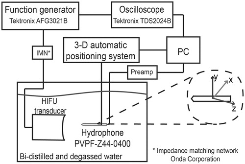
HIFU radiator was spherically curved and had a 2 MHz nominal frequency (model 2-20-20/1, Onda). For characterisation purposes, the transducer driving signal was configured at 10 Vpp/25 cycles sinusoidal burst with 10 Hz repetition rate in order to preserve hydrophone performance [Citation16]. A function generator (model AFG3021B, Tektronix, Beaverton, OR) was used to excite the transducer at its operating frequency: 1.965 MHz. Data collected with the hydrophone was stored in a PC for further radiation pattern reconstruction.
The transducer output pressure was calculated from the RMS voltage (Vrms) data acquired by the hydrophone during acoustic characterisation at low power (∼390 mW). In order to do so, the free-field spatial peak temporal average intensity (Ispta) values were determined by using the relationship
(1)
where ρ is the density of the medium, c is the propagation speed and S is the hydrophone sensitivity (0.125 V/MPa, in this case). Non-linear propagation was neglected after verifying that the signals recorded by the hydrophone at the focus did not present non-linearities. The fast Fourier transform (FFT) of these signals confirmed that the second and third harmonics of them were attenuated below −80 dB at the transducer operating frequency. At low power, the Ispta at focal point in free field was 17.18 W/cm2. By linear extrapolation, the Ispta estimated during experiments ranged from 220 W/cm2 up to 880 W/cm2.
FEM software was used to solve the time-harmonic wave equation from a spherically concave radiator. In order to simplify the complexity of the model, the problem was reduced to 2D axial symmetry geometry. The time-harmonic acoustic wave equation is given by
(2)
where p is the acoustic pressure (Pa), ω is the angular frequency (rad/s), and cs is the sound propagation speed (m/s). This equation can be used to calculate the radiation patterns for axis-symmetric apertures by using FEM without restrictions on the uniformity of the radiating distribution [Citation17].
depicts the geometry of the HIFU transducer proposed for the modelling. Concavity depth h was 3.72 mm; it was calculated from a 10-measure average done with a digital caliper (Mitutoyo, Kanagawa, Japan). shows the geometrical parameters (which are given by the manufacturer) used for the numerical model. As the propagating medium is considered as near to lossless, the sub-domain was configured as water with density ρ = 1000 kg/m3 and sound speed c = 1500 m/s at 25 °C.
Figure 2. 2D axis-symmetric FEM geometry used to model the acoustic propagation in water. The subdomain represents the propagating medium, water. Boundary 1 is the symmetry axis, boundaries 2 and 3 were configured as the impedance condition, and boundaries 4 and 5 were set as a rigid baffle and as the acoustic radiator, respectively. Radiator radius is 10 mm.
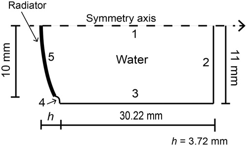
Table 1. HIFU transducer nominal characteristics given by the manufacturer.
According to , boundary 1 was considered as the symmetry axis. Boundaries 2 and 3 were configured with acoustic impedance condition modelled by the equation
(3)
where n is the unit vector normal to the boundary, ∇ p is the normal derivative of the pressure, ρ0 is the density of the medium, and Z is the acoustic impedance of the boundary (Z = ρc), which has the same value of that of the propagating medium in order to diminish wave reflections [Citation17]. Boundary 4 acted as a hard wall which considers the piezoelectric element inside a rigid baffle which has no normal velocity [Citation17–20]. Finally, boundary 5 was configured as the acoustic pressure source of a continuous signal with uniform amplitude of 30,060 Pa (pressure value calculated from acoustic characterisation) and 1.965 MHz operating frequency.
FEM mesh consisted of 10 triangular elements per wavelength (λ/10) in the propagating medium, i.e. 294,977 elements. The model was solved for finer meshes up to 20 elements per wavelength to make a convergence test of the result and the relative error obtained was 0.0003%. By using coarser meshes, e.g. six elements per wavelength, the relative error can be 0.015%. The solution time for λ/20 mesh was 24 min (8.84 GB physical memory/9.85 GB virtual memory) and for λ/6 mesh was 25 s (1.28 GB physical memory/1.46 GB virtual memory). The FEM models were solved by means of the software COMSOL Multiphysics 4.4 (COMSOL, Burlington, MA) in a workstation with 64 GB RAM and 3 GHz 4-core processor.
In order to compare the simulated data with measured acoustic patterns of the radiator, contours at 1/3 of maximum pressure, full width at half maximum (FWHM) pressure and full length at half maximum (FLHM) pressure were obtained. In this way, contours, at −3 dB and −6 dB pressure decay, were traced in both transversal and axial focal zones [Citation21]. The comparison between data was made by means of three parameters: (1) form factor fc, (2) ellipsoidal shape ratio Er, and (3) mean Euclidean distance.
Form factor fc is defined as the relation between the intersection area of two lines, A and B, and the total area below those lines, fc = (A∩B)/(AUB) [Citation22]. This factor computes the interdependence or association degree between two variables, similar to a correlation coefficient R [Citation22]. Due to the focus ellipsoidal shape produced by a HIFU beam [Citation13], it was possible to obtain a percentage of similarity between both focal zones, the experimental and the simulated. The ellipsoidal shape ratio Er shows the likeness between two ellipsoidal contours by obtaining the quotient between the minor and major axis in each ellipse. Euclidean distance between two points A1(x1,y1) and A2(x2,y2) indicates the metric difference that exists between two trajectories to be compared. Therefore, the mean Euclidian distance and its standard deviation were calculated for each pair of contours in xy- and xz-planes.
Hybrid conical applicator design based on FEM modelling
A 10% acrylamide concentration for the polyacrylamide gel was selected for its appropriated sound and bulk properties [Citation4] as coupling medium. Low density polyethylene had an acoustic impedance of 1.79 MRayl [Citation23], which was relatively close to water (1.5 MRayl) and soft tissue values (liver, 1.69 MRayl). Attenuation coefficient for low density polyethylene presented a linear response as a function of frequency, around 10 dB/cm at 2 MHz [Citation23]. The acoustic properties of the distinct working materials suggested a good acoustic coupling among them. All these characteristics make them suitable for efficient haemostasis applications.
depicts the proposed HIFU haemostasis hybrid device. A low density polyethylene hollow cone filled with polyacrylamide was attached to the HIFU transducer to adequately deliver the ultrasonic energy to the target. Cone geometry and dimensions were defined in order to scarcely interfere with the HIFU transducer 3D pressure pattern. Therefore, two acoustic field propagation models were done: 1) for the cone immersed in water and 2) for the cone haemostasis application.
Figure 3. Hybrid applicator proposal for acoustic haemostasis and FEM geometry for field modelling. (A) Low density polyethylene (LDPE) cone filled with polyacrylamide (PAA) gel as the acoustic coupling medium to deliver ultrasound energy to the target. (B) Acoustic propagation modelling for the applicator. Boundaries 1 and 2 were set as the symmetry axis. Boundaries 3–5 were configured as the liver impedance condition, and boundaries 6–10 were set as air impedance condition to simulate a haemostasis application. Boundaries 6–10 were configured as the water impedance condition for further comparison with the acoustic characterisation of the applicator. Boundary 11 represents the transducer surface.
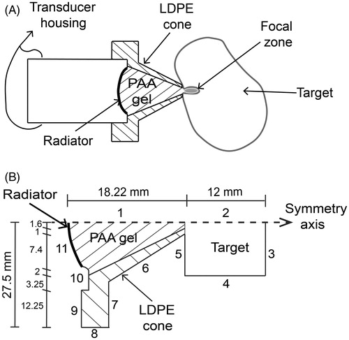
The acoustic propagation modelling for the cone immersed in water case was made in order to observe possible field differences in comparison to measurements. shows the FEM geometry used for the acoustic field modelling of the applicator and its dimensions; while acoustic properties of the selected materials taken from [Citation4,Citation23–25] are shown in . Boundaries 1 and 2 were configured as the symmetry axis. Medium geometry conditions were defined as water acoustic impedance at boundaries 3 to 9. Boundary 10 was configured as a rigid baffle, simulating the transducer housing. Boundary 11 was defined as the acoustic pressure source (p0 = 30,060 Pa). The model was solved for meshes up to 20 elements per wavelength and the relative error obtained between λ/10 and λ/20 was 0.01%. By using coarser meshes, e.g. six elements per wavelength, the percentage relative error could be 0.23. The resulting mesh for λ/10 contained 242,588 triangular elements.
Table 2. Acoustic properties of the materials used for the applicator.
Based on the geometry shown on , the acoustic field for the haemostasis application case was modelled. FEM conditions at boundaries 3 and 4 were determined with impedance condition (liver acoustic impedance). Boundaries 5 to 9 were established as air impedance condition, and boundary 10 simulated a rigid baffle (normal velocity = 0). Finally, the pressure source (p0 = 30,060 Pa) was associated to boundary 11. As before, the relative error for λ/20 was 0.14% and for λ/6 was 1.57%; by taking as reference the solution for λ/10, the resulting mesh had 228,731 triangular elements.
Experimental resources
The conical applicator proposed here requires a 10% polyacrylamide gel as an acoustic coupling medium. A liver phantom was fabricated with 7% polyacrylamide gel and 9% bovine serum albumin in order to visually detect the HIFU focus due to the protein denaturation. The gel fabrication was made according to the protocol described by Choi et al. [Citation26] and Lafon et al. [Citation27]. Cone inner volume (10.85 mL) was determined before gel fabrication. For the liver phantom, a total volume of 20 mL of gel was fabricated.
The cone design was made to be perfectly matched with the transducer housing geometry. The low density polyethylene cone was attached to the transducer with four screws. The polyacrylamide solution was injected with a syringe into the cone by making a little pressure with the needle against the inner wall of the cone. The liquid polyacrylamide was poured slowly to ensure absolute geometric matching. After several trials and by verifying by removing the plastic shell of the conical gel, it was observed that this technique was the best to eliminate air bubble formation. After gel polymerisation, water drops were applied to the cone tip to keep it hydrated. The applicator was preserved for further use.
The HIFU haemostatic hybrid applicator was acoustically characterised in order to obtain the radiation pattern next to the cone tip. Similarly to the HIFU field characterisation, the applicator was fixed inside a tank filled with bi-distilled and degassed water. The hydrophone was placed at 1 ± 0.2 mm from the applicator tip. The scan was carried out with a 3D automatic positioning system in order to acquire the data needed to obtain the field distribution (see ).
The temperature dependence of sound speed through the proposed materials was measured in the temperature interval of 20–60 °C. The speeds of sound for the coupling medium and the liver phantom were measured by using the pulse-echo method with a two-needle–reflector system [Citation28]. The needle-reflector system was placed in parallel to a plane transducer (model 120-0204-S, 2.25 MHz Harisonic); both the reflectors and the transducer were fixed at the same mechanical support. Afterwards the needles were inserted into the gel and the whole system was immersed in a thermostatic bath (model TU-20D Tempunit, Techne, Bibby Scientific, Burlington, NJ) filled with bi-distilled degassed water. The thermostatic bath regulated the water temperature and a mercury thermometer (resolution of 0.1 °C, Brannan, Cleator Moor, UK) was used to verify it. For the low density polyethylene, a cylindrical sample of this material was used instead of the needle-reflector and its own plane faces were used as reflectors. The speed of sound was calculated by maximum peaks time difference.
In an ultrasonic transmission it is very important to assure a good impedance matching. A high impedance difference between its two opposite sides means that almost all the energy is being reflected into the associated electrical and mechanical transmission line. Under these conditions the incoming signal would be mixed with the resulting reflected one, thus creating a standing wave in the transmission line. The relation between the two signals of minimum and maximum voltage is called the standing wave ratio (SWR). For instance, a 1:1 SWR means that there is no reflected energy. Hence, the SWR is an index of the electrical coupling system.
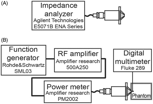
For the SWR measurement the HIFU transducer was excited with a continuous sine wave at very low power (500 mV) and also with 20 W. In the first case, an impedance analyser (model E5071B ENA Series, Agilent Technologies, Santa Clara, CA, see ) was used. In the second case a power meter (model PM2002, Amplifier Research, Souderton, PA) was placed between the excitation signal and the HIFU transducer in order to measure the incident and reflected powers (see ). Impedance coupling tests were performed with the hybrid probe emitting in both the air and the liver phantom.
Figure 4. SWR and induced temperature measurement. (A) SWR measurement at low power with the hybrid applicator radiating in air. (B) SWR measurement during experimentation to assure electrical coupling. Temperature increment measurement during experiments with a thermocouple placed at the focus.
After the SWR was measured at low power, the hybrid applicator tip was applied to the liver phantom in order to induce a thermal lesion on it. Coupling gel was added between the phantom and the said tip to eliminate possible air gaps. A thermocouple embedded into the phantom recorded the temperature increments at the focus with a digital multimeter (model 289, Fluke, Everett, WA); even though this method could induce errors due to viscous heating artefacts [Citation29]. The HIFU haemostasis applicator was excited with sinusoidal continuous signals (from 1–20 W with increments of 5 W) for approximately 120 s, and centred at the transducer operating frequency. Exposure time was chosen according to the reported average time needed to achieve haemostasis [Citation2,Citation8].
Ex vivo experimentation was done using fresh chicken liver. Samples were horizontally attached to the lower middle part of the tip. As mentioned above, coupling gel was added to the applicator tip. The powers applied to drive the hybrid applicator were 10 W, 15 W and 20 W with an approximate exposure time of 120 s.
Results
Modelled vs. measured HIFU acoustic field distributions
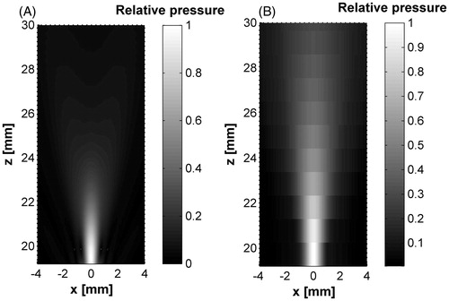
The experimental acoustic field distributions for the HIFU transducer were obtained in the propagation and transversal planes. shows both simulated and measured fields behaviours. Modelled focal zones showed good concordance with the acoustic characterisation data in both planes. Transverse planes (at the highest intensity point) showed a focal diameter near to 1 mm. The transducer nominal focal distance was 20 mm, whereas the experimental value was measured at 20.72 ± 0.24 mm, and the simulated focus appeared at 19.79 mm.
Figure 5. Modelled and measured acoustic radiation patterns of the HIFU transducer. (A) HIFU acoustic fields over propagation xz-plane from FEM model. (B) Experimental measurement in xz-plane. (C) xy-plane pressure at focus (∼20 mm) by FEM simulation. (D) Transversal plane pressure at focus by acoustic characterisation. All data were normalised.
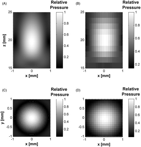
shows the axial pressure distributions for both measured and simulated data. It can be seen that the maximum pressure reached around 620 kPa at ∼20 mm. The relative error between both absolute maximum pressures was 0.742%. On the other hand, the FLHM in pressure curves, for both measured and simulated data, were 8.46 mm and 6.98 mm, respectively. The difference between both FLHM values was only of 1.47 mm.
Figure 6. Measured and simulated data comparison for z-axis and sectional planes in the HIFU transducer. (A) Axial pressure distribution measured and simulated for the transducer acoustic field in water. Measured data were obtained from hydrophone scans starting at 2 mm from the edge of the housing. (B) Transversal plane contours at focus (∼20 mm). (C) Propagation plane contours at focal zone. Contours data were normalised.
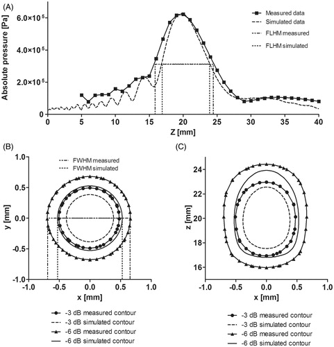
Data comparison was based on form factor fc, ellipsoidal shape ratio Er and mean Euclidean distance, as mentioned above. Normalised pressure fall contours at −3 dB and −6 dB in the xz- and xy-planes were determined in order to calculate these parameters. shows a comparison between the areas simulated and measured for each contour, and a summary of the percentage values calculated for the three parameters.
Table 3. Enclosed areas and percentage values between normalized −3 dB and −6 dB pressure contour in the acoustic fields (measured and simulated).
shows the −3 dB and −6 dB pressure contours measured and simulated for the transducer at the transversal and axial focal zones. An acceptable agreement in the shape of focuses was obtained according to the ellipsoidal relation between the contours (see ). FWHM in pressure for both measured and simulated data were 1.35 mm and 1.05 mm, respectively. The difference between both FWHM values was small: 0.3 mm.
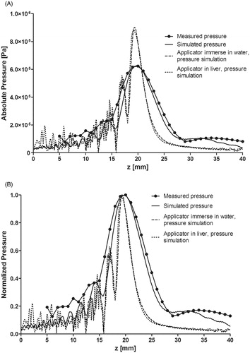
shows the absolute pressure distribution for measured data, and three simulation cases: radiator, applicator immersed in water and a haemostasis application case. After including the applicator in the simulations, the focus length was shortened and the maximum pressure was increased to 133% of the value without the applicator. shows the normalised pressure distribution for the four cases. Certain pressure peaks appear after placing the applicator into the simulations while the focus was slightly displaced towards the transducer face, probably due to impedance difference at the cone boundaries.
Figure 7. Pressure distribution along beam path from measured and simulated data. (A) Absolute values of the pressure distribution with only the HIFU radiator, and the haemostatic applicator simulation when it was immersed in water and with extracorporeal usage. (B) Normalised pressure distribution of the measured and simulated data.
Results for the hybrid conical applicator
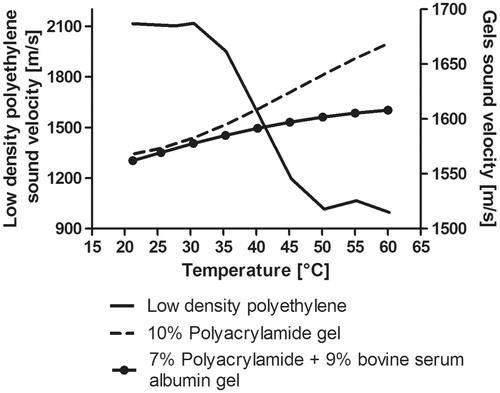
The temperature dependence of sound speed through the tested materials is shown in . The first material, polyacrylamide gel, was fabricated to be used as an ultrasonic coupling medium; its sound speed at 20 °C was 1568.4 m/s, and 1668.9 m/s at 60 °C. The liver phantom had a sound speed of 1562.1 m/s at 25.5 °C and 1608.1 m/s at 60 °C. The sound speed of low density polyethylene was 2115.1 m/s at 20 °C and 996.92 m/s at 60 °C. Polyacrylamide-based gels had an increasing response of sound speed according to temperature increase; meanwhile low density polyethylene sound speed response was opposite to that of the gels, i.e. the sound velocity decreased when the temperature increased. This behaviour could produce an impedance mismatch in the hybrid cone when over-passing 40 °C.
Figure 8. Temperature dependence of sound speed measured for the gels and the low density polyethylene. Left vertical axis: Sound speed temperature dependence for the low density polyethylene material (used for the cone). Right vertical axis: Temperature dependence of the 10% polyacrylamide gel (coupling medium) and 7% polyacrylamide +9% bovine serum albumin gel (liver phantom).
A hybrid haemostasis applicator acoustic pattern in water was modelled (see ). Moreover, the applicator prototype was characterised in order to obtain its spatial acoustic distribution. shows the normalised radiation patterns for the hybrid applicator starting from the probe tip. It can be seen that the radiation pattern in the acoustic characterisation was larger than that of the simulation results.
Figure 9. Hybrid applicator acoustic pattern from the cone tip. (A) Modelled acoustic field, (B) measured acoustic field. Some pressure beam variation can be seen between the modelled and measured fields which could be due to the non-ideal lateral radiations and the effective acoustic coupling between the materials: low density polyethylene, 10% polyacrylamide gel and water.
Acoustic field differences are closely related to the problem idealisation done for the FEM simulation. Coupling between materials, spurious applicator vibrations [Citation30,Citation31], and different temperature dependence of the sound speed for each material could produce slight differences in the patterns. Non-ideal ultrasound propagation, non-ideal material vibrations, phantom density changes, for example, should be considered in further research. Nevertheless, it is clear that the FWHM, FLHM and absolute pressure values in both the preliminary simulated here and the measured acoustic fields for our device have a reasonably good concordance, as shown in . The difference between measured and simulated FWHM was 0.3 mm and 1.47 mm for the FLHM, which is sufficient for our current aim in this work; i.e. an initial validation of our new design.
Experimental heating and SWR measurements
shows the experimental set-up for the temperature measurements within the phantom. The maximum temperature reached (Tmax) was 43.4 °C after 122 s when the applicator was driven at 10 W and 88.7 °C after 85 s at 20 W. For all power cases, the average initial temperature Ti of the phantom was 18.5 °C. The temperature increment (ΔT = Tmax -Ti) was 24.9 °C at 10 W and 70.2 °C at 20 W. As described before, SWR measurement at low power was useful to determine the hybrid applicator coupling at the transducer operating frequency. HIFU transducer SWR was 2.0; SWR from the whole hybrid applicator was 1.53 and the SWR after placing the liver phantom at the applicator tip was 1.35. Average SWR obtained from electrical power meters during experimentation was 1.31. summarises the electrical power measurements, exposure time, and temperature increments obtained from phantom experimentation.
Figure 10. Experimental set-up for induced temperature measurement inside the liver phantom and ex vivo experimentation. (A) Hybrid applicator set-up for temperature measurement in the liver phantom. (B) Hybrid applicator set up for ex vivo experimentation. (C) HIFU effects in chicken liver at 10 W. (D) HIFU effects in chicken liver at 20 W.
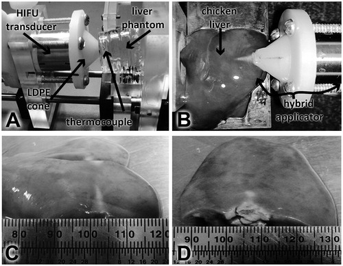
Table 4. Electrical power, SWR and temperature measurements in phantom experimentation.
Ex vivo experimentation was carried out for the five electrical driving powers proposed in the temperature measurements in the phantom; damage was easily observed even with only 10 W driving power. shows the set-up for this purpose; the lesion formed in the liver sample presented a pattern consistent with the distribution of the acoustic pressure. shows the thermal damage in the liver sample after 120 s for a 10 W driving signal. Transversal size of the lesion was ∼4 mm and its length was ∼13 mm. HIFU effects in chicken liver at 20 W can be observed in ; the lesion transversal size was ∼12 mm and its axial length was ∼10 mm. It can be seen that the area of the induced damage was larger after the electrical power was increased while the sonication time stayed as stated before.
Average SWR measured at low power for the (hybrid applicator–chicken liver) set-up was 1.3. From measurements obtained during experimentation, the SWR was 1.33 at 10 W, 1.2 at 15 W and 1.35 at 20 W. Reflected power in all cases was less than 0.5 W. These results and phantom experimentation (see ) data confirm the good performance and haemostasis viability of the low-power device developed.
Discussion
One of the purposes of the development of this technique was to obtain a device that could be used both inside the operating room and in ambulatory attention. Therefore, it was important to develop an applicator which could attain high energy transference efficiency through a biocompatible coupling material. The achievement of a low power prototype for haemostasis would make it suitable for its portability. In this work, the design of a hybrid applicator for haemostasis was based on the results of acoustic propagation simulation. Temperature and SWR measurements demonstrated that we obtained an applicator of better efficiency and lower electrical driving power than the prototypes developed by Martin et al. [Citation3], Prokop et al. [Citation4], Vaezy et al. [Citation5], and Zderic et al. [Citation10].
The impact on the level of ultrasonic transmission produced by the coupling performance between a material and the HIFU transducer is one of the main problems to solve in order to design conical haemostasis applicators. By means of FEM modelling, the acoustic field simulation of a concave transducer was solved. The materials chosen for the conical applicator proposed here are low density polyethylene filled with a 10% polyacrylamide gel. Both materials present acoustic properties that diminish the ultrasonic transmission losses along the applicator. Moreover, first approximation heating modelling suggested that the temperatures at the tip of the applicator (low density polyethylene-polyacrylamide gel) could raise a reasonable value between 40–50 °C when the maximum temperature at focus reaches 89 °C.
Some small differences between FEM simulations and experimental acoustic patterns were mainly due to the different resolution used to obtain the acoustic field. shows that the pressure distribution from the measured and modelled data had a close relation in respect to the higher intensity spot location. Also, the ellipsoidal relation showed similarities over 87%, and mean Euclidean distance was 0.18 ± 0.022 mm at the transversal plane and 2.33 ± 1.25 mm at the axial plane. The differences between FWHM and FLHM values were 0.3 mm and 1.47 mm, respectively.
Moreover, FEM modelling was done under ideal conditions in order to solve the problem with a moderate calculation effort. Additionally, the model can give more details than the conventional experimental characterisation, with a reasonable calculation time (less than 1 min). However, the measured maps have mechanical restrictions caused by the 3D positioning system. Other non-ideal aspects that were not considered in the model and could emerge during experimentation are, for example, transducer non-uniform vibrations, possible radiations of spurious vibrations from the peripheral transducer zones [Citation17,Citation30,Citation31]. In the modelling, for example, it was assumed that the radiation curvature was entirely spherical, and that it radiated homogeneously into the medium. Besides, its transient response was not included in the stationary regime simulations.
Conical geometry has been defined in order to attain the desired radiation pattern. As can be seen in , the axial pressure distribution from FEM simulations including the applicator converged at the transducer nominal focal distance. The resulting focus depth with the applicator was smaller than that of the transducer radiation pattern. Some pressure variations before the focal distance in the haemostasis application simulation could be due to acoustic impedance changes in the phantom–cone–air boundaries. Moreover, the possible presence of bubbles inside the polyacrylamide gel could produce both non-uniform acoustic and heating distributions within the cone. In further research, heating patterns inside both the applicator and the phantom should be explored.
Haemorrhage control effectiveness by using a surgical haemostasis treatment depends on both length and depth of the wound. Therefore, it is desirable to achieve haemostasis in the shortest time. FEM modelling and experiments were carried out to analyse the pressure distribution in water and haemostasis application. The focal temperature measured in a liver phantom was performed by taking into account a similar treatment time reported by Brentnall et al. [Citation2]. Furthermore, it would be convenient to test the hybrid haemostasis applicator during in vivo experiments, in order to get a supplementary evaluation of the prototype performance.
Conclusion
The feasibility study of a low power hybrid applicator for haemostasis usage was presented in this work. The applicator was designed and developed from numerical data obtained by means of our acoustic propagation simulations. SWR measurements obtained during experimentation confirmed the good energy transference in the complex system formed by transducer–applicator–sample(phantom/liver). In fact, the average reflected power measured was less than 0.5 W. Temperature and SWR measurements demonstrated that we obtained an applicator of better efficiency and lower electrical driving power than other prototypes. These results encourage us to test the low power haemostasis applicator presented in this work with additional in vivo trials in order to get a more efficient, fully tested device able to be used in the operation room. The modelling of some spurious effects, possible non-linear aspects and heating distribution could be addressed during further research.
Acknowledgements
The authors acknowledge the CINVESTAV-IPN for all the facilities given to develop this work and the invaluable assistance of José Hugo Zepeda Peralta and Rubén Pérez Valladares during the experimentation stages.
Declaration of interest
R.M.V. acknowledges CONACYT (Mexico) for fellowship number 219341 and the ‘Ultrasonic Systems and Technologies Laboratories (ITEFI-CSIC)’ for a scientific stay in Madrid related to this work. The authors acknowledge the funding given by the ECOS-ANUIES-CONACYT M10-S02 programme, the CONACYT-F-SALUD 201590 project, CONACYT-F-SALUD 201256 and the Joint Cooperation Fund Mexico–Uruguay (SRE-AUCI) 2012–2013. The authors alone are responsible for the content and writing of the paper.
References
- Vaezy S, Zderic V. Hemorrhage control using high intensity focused ultrasound. Int J Hyperthermia 2007;23(2):203–11
- Brentnall MD, Martin RW, Vaezy S, Kaczkowski P, Forster F, Crum L. A new high intensity focused ultrasound applicator for surgical applications. IEEE Trans Ultrason Ferroelectr Freq Control 2001;48:53–63
- Martin RW, Vaezy S, Proctor A, Myntti T, Lee JBJ, Crum LA. Water-cooled, high-intensity ultrasound surgical applicators with frequency tracking. IEEE Trans Ultrason Ferroelectr Freq Control 2003;50:1305–17
- Prokop AF, Vaezy S, Noble ML, Kaczkowski PJ, Martin RW, Crum LA. Polyacrylamide gel as an acoustic coupling medium for focused ultrasound therapy. Ultrasound Med Biol 2003;29:1351–8
- Vaezy S, Vaezy S, Starr F, Chi E, Cornejo C, Crum L, et al. Intra-operative acoustic hemostasis of liver: Production of a homogenate for effective treatment. Ultrasonics 2005;43:265–9
- Vaezy S, Martin R, Yaziji H, Kaczkowski P, Keilman G, Carter S, et al. Hemostasis of punctured blood vessels using high-intensity focused ultrasound. Ultrasound Med Biol 1998;24:903–10
- Vaezy S, Martin R, Crum L. High intensity focused ultrasound: A method of hemostasis. Echocardiogr J Cardiovasc Ultrasound Allied Tech 2001;18:309–15
- Vaezy S, Noble ML, Keshavarzi A, Paun M, Prokop AF, Cornejo C, et al. Liver hemostasis with high-intensity ultrasound: Repair and healing. J Ultrasound Med 2004;23:217–25
- Vaezy S, Martin R, Keilman G, Kaczkowski P, Chi E, Yazaji E, et al. Control of splenic bleeding by using high intensity ultrasound. J Trauma-Injury Infect Crit Care 1999;47:521–5
- Zderic V, Keshavarzi A, Noble ML, Paun M, Sharar SR, Crum LA, et al. Hemorrhage control in arteries using high-intensity focused ultrasound: A survival study. Ultrasonics 2006;44:46–53
- Goertz DE. An overview of the influence of therapeutic ultrasound exposures on the vasculature: High intensity ultrasound and microbubble-mediated bioeffects. Int J Hyperthermia 2015;31:134–44
- Shaw CJ, ter Haar GR, Rivens IH, Giussani DA, Lees CC. Pathophysiological mechanisms of high-intensity focused ultrasound-mediated vascular occlusion and relevance to non-invasive fetal surgery. J R Soc Interface 2014;11:20140029
- Haar GT, Coussios C. High intensity focused ultrasound: Physical principles and devices. Int J Hyperthermia 2007;23:89–104
- Martinez R, Vera A, Leija L. Portable and tunable continuous wave driver from 1 MHz to 10 MHz for HIFU transducers. PAHCE 2011;2011:122–6
- Martinez R, Vera A, Leija L. Finite element HIFU transducer acoustic field modeling evaluation with measurements. PAHCE 2012;2012:101–4
- Shaw A, Ter Haar GR. Requirements for measurement standards in high intensity focused (HIFU) ultrasound fields. Teddington (UK): National Physical Laboratory, Institute of Cancer Research, 2006
- Gutiérrez MI, Calás H, Ramos A, Vera A, Leija L. Acoustic field modeling for physiotherapy ultrasound applicators by using approximated functions of measured non-uniform radiation distributions. Ultrasonics 2012;52:767–77
- Hutchins DA, Hayward G. The radiated field of ultrasonic transducers. In: Thurston RN, Pierce AD, eds. Physical Acoustics. London: Academic Press, 1990, pp. 1–80
- Kino GS. Acoustic Waves: Devices, Imaging, and Analog Signal Processing. Engelwood Cliffs, (NJ): Prentice-Hall, 1987
- Rodriguez FJ, Ramos A, San Emeterio JL, Riera E. Influencia de las condiciones de contorno en la radiación ultrasónica impulsional de un transductor de inmersión. An Física 1993;89:25–44
- Teja JL, Vera A, Leija L. Acoustic Field Comparison of High Intensity Focused Ultrasound by using Experimental Characterization and Finite Element Simulation. Boston, MA: Proceedings of the 2013 COMSOL Conference, 2013
- Moreno-Baron L, Cartas R, Merkoci A, Alegret S, del Valle M, Leija L, et al. Application of the wavelet transform coupled with artificial neural networks for quantification purposes in a voltammetric electronic tongue. Sensors Actuators B Chem 2006;113:487–99
- He P, Zheng J. Acoustic dispersion and attenuation measurement using both transmitted and reflected pulses. Ultrasonics 2001;39:27–32
- Azhari H. Appendix A: Typical Acoustic Properties of Tissue. Basics of Biomedical Ultrasound for Engineers. Hoboken, (NJ): Wiley, 2010, pp. 313–14
- Selfridge AR. Approximate material properties in isotropic materials. IEEE Trans Sonics Ultrason 1985;32:381–94
- Choi MJ, Guntur SR, Lee KL, Paeng DG, Coleman A. A tissue mimicking polyacrylamide hydrogel phantom for visualizing thermal lesions generated by high intensity focused ultrasound. Ultrasound Med Biol 2013;39:439–48
- Lafon C, Kaczkowski PJ, Vaezy S, Noble M, Sapozhnikov OA. Development and characterization of an innovative synthetic tissue-mimicking material for high intensity focused ultrasound (HIFU) exposures. IEEE Ultrason Symp 2001;2:1295–8
- Lopez-Haro S a., Vera A, Leija L. Evaluation of an ultrasonic propagation speed measurement system in the temperature range from 20 °C to 45 °C. PAHCE 2010;2010:85–9
- Maruvada S, Liu Y, Pritchard WF, Herman BA, Harris GR. Comparative study of temperature measurements in ex vivo swine muscle and a tissue-mimicking material during high intensity focused ultrasound exposures. Phys Med Biol 2012;57:1–19
- Azbaid A, Ramos A, Pérez-Valladares R, Calas H, Leija L. Preliminary analysis and simulation of the influence of radiations from the rim of therapeutic transducers in the irradiated acoustic field. PAHCE 2010;2010:121–5
- Azbaid A, Ramos U, Ruiz U. Approaching the possible origin of non-ideal radiations in ultrasonic thermal therapy coining from the applicators housing and modifying the expected radiation patterns. PAHCE 2013;2013:1–6