
Abstract
Purpose In pulmonary veins (PVs) isolation (PVI), radiofrequency (RF) energy is often used to create a linear lesion for blocking the accessory conduction pathways around PVs. By using transient finite element analysis, this study compared the effectiveness of phase-shift mode (PsM) ablation with bipolar mode (BiM) and unipolar mode (UiM) in creating a continuous lesion and lesion depth in a 5-mm thick atrial wall. Materials and methods Computer models were developed to study the temperature distributions and lesion dimensions in atrial walls created through PsM, BiM, and UiM. Four phase-shift angles – 45°, 90°, 135°, and 180° – were considered in PsM ablation (hereafter, PsM-45°, PsM-90°, PsM-135°, and PsM-180°, respectively). Results At 60 s/30 V peak value of RF voltage, UiM and PsM-45° did not create an effective lesion, whereas BiM created a lesion of maximum depth and width approximately 1.01 and 1.62 mm, respectively. PsM-135° and PsM-180° not only created transmural lesions in 5-mm thick atrial walls but also created continuous lesions between electrodes spaced 4 mm apart; similarly, PsM-90° created a continuous lesion with a maximum depth and width of nearly 4.09 and 6.12 mm. Conclusions Compared with UiM and BiM, PsM-90°, PsM-135° and PsM-180° created continuous and larger lesions in a single ablation procedure and at 60 s/30 V peak value of RF voltage. Therefore, the proposed PsM ablation method is suitable for PVI and linear isolation at the left atrial roof for treating atrial fibrillation.
Introduction
Background
Atrial fibrillation (AF) is the most common cardiac arrhythmia in the general population. AF morbidity continuously increases with age. The common symptoms of AF include unpleasant and irregular heartbeats, impaired haemodynamic response caused by loss of atrioventricular synchrony, and vulnerability to thromboembolic complications. Thus, a successful AF treatment has three positive consequences: it restores the sinus rhythm, normalises cardiac haemodynamics, and alleviates the vulnerability to thromboembolism.
In the past, common therapies for AF were anti-arrhythmic drugs or the surgical maze procedure. However, both these approaches may entail high recurrence and severe injury during open chest surgery. Circumferential pulmonary vein isolation (PVI) and continuous linear ablation in the atrium have been demonstrated to be highly effective and reliable interventions against drug-resistant refractory AF. Conventionally, PVI is performed through point-to-point ablation using unipolar RF energy guided by an electromagnetic navigation system (Carto™, Biosense Webster, Diamond Bar, CA, or Ensite™, St Jude Medical, St. Paul, MN) for reducing radiation exposure. This RF ablation technique delivers a sinusoidal voltage from the active electrode to the dispersive electrode and creates a point lesion slightly larger than the size of the active electrode tip. In conventional unipolar ablation continuous lesions can be created by performing a series of discrete point ablation procedures, which requires a skilled operator; consequently, these procedures are often time intensive. Moreover, AF may recur because of incomplete linear lesion formation (i.e. presence of gaps), resulting in partially recovered accessory conduction pathways. Therefore, developing specialised RF ablation procedures that facilitate the easy creation of continuous lesions in the region of the ostium of the PVs is essential for complete PV isolation.
The phase-shift angle RF ablation technique has recently been clinically investigated for treating AF, and the first related clinical result for PVI was published by Wieczorek et al. [Citation1]; they reported that the phase-shift angle RF energy used in the PVI procedure was safer and that the procedure was substantially shorter compared with the conventional procedure [Citation2]. Spitzer et al. [Citation3] conducted several clinical studies in which they compared the success rate and effectiveness of point-to-point ablation and multi-electrode phase RF ablation in 539 patients. Bulava et al. [Citation4] performed a randomised comparison between phase-shift angle RF ablation and point-to-point ablation for AF and reported similar clinical success rates for both procedures.
A review of relevant literature revealed that no finite element model has yet been developed to comparatively study the effectiveness of phase-shift ablation (PsM), bipolar ablation (BiM), and unipolar ablation (UiM) in creating continuous lesions; in particular, the role of the phase-shift angle has not been investigated. In this paper, by using transient finite element analysis we established computer models to compare the effectiveness of the three ablation modes in creating a continuous linear lesion. In addition, for determining the desirable lesion depth in PVI, we analysed the relationship between the initial phase angle and lesion size in PsM ablation.
Methods
Phase-shift ablation
Most existing computer models of cardiac ablation use the quasi-static electrical equation to resolve the electro-thermal coupled problem. In this quasi-static approach, the direct current (DC) voltage is applied to the finite element model of the catheter electrode [Citation5,Citation6], meaning that the quasi-static method imitates the RF voltage as a root mean squared value (DC); hence, this method cannot be used to numerically determine the influence of phase angle on lesion formation. In this study the quasi-static method is replaced by the transient approach for relatively more realistically investigating the effect of phase-shift angle on lesion formation. Three elements of RF voltage (amplitude, phase angle, and frequency) are loaded to the finite element model for the catheter electrodes. Therefore, the transient approach can simulate the effect of phase-shift angle between RF sources on cardiac ablation. The transient finite element analysis and the principle of phase-shift angle ablation are elucidated in the text that follows.
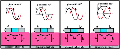
In contrast to conventional ablation, the phase-shift RF technique simultaneously delivers a pair of RF voltages at the same frequency and constant amplitude but different initial phase angle to the adjacent active electrodes [Citation7–10]. In our study the phase-shift angles between the two RF sources are adjusted in the range 45–180° in a step size of 45°. The phase-shift angle between the two RF sources simultaneously induces a voltage gradient in the adjacent active and dispersive electrodes, leading to the simultaneous flow of both bipolar and unipolar current in the myocardium, as illustrated in . The bipolar current (iab), which can create continuous lesions, flows between the active electrodes, whereas the unipolar current (ia or ib), which can create deep lesions, flows between each pair of active and dispersive electrodes. Through this method, we can control the amplitude of bipolar and unipolar current by varying not only the RF voltage amplitude but also the phase-shift angle; this means that we can adjust the delivery of bipolar and unipolar energy for creating lesions with the desired depth as well as continuous lesions in a single ablation procedure. Furthermore, compared with the conventional approach (BiM and UiM), the PsM approach can easily create continuous and deep lesions in the ostium of the PVs.
Figure 1. Four kinds of phase shift ablation modes (PsM-45°, PsM-90°, PsM-135°and PsM-180°) with a phase shift angle range of 45–180° in 45° step sizes.
Principle of unipolar and bipolar power control
As shown in , active electrode ‘a’ is set at Va(t) = A sin ω t, and active electrode ‘b’ is set at Vb(t) = A sin (ω t + ϕ); the dispersive electrode is grounded. According to the basic circuit principle and trigonometric relationship, the bipolar voltage between the active electrodes is
(1)
Therefore, the bipolar voltage amplitude can be controlled by varying the phase-shift angle. The biggest advantage of PsM ablation is the coexistence of bipolar and unipolar voltages: the bipolar energy creates continuous lesions, and the unipolar energy ensures adequate lesion depth.
In PsM ablation, bipolar energy and unipolar energies can be adjusted in a single ablation procedure. According to the basic circuit principle, the unipolar and bipolar power can be determined using EquationEquations (2)(2) and Equation(3)
(3) , respectively:
(2)
(3)
where Rui and Rbi represent the unipolar and bipolar impedances, and A and 2Asin ϕ/2 are the amplitudes of the unipolar and bipolar RF voltage, respectively.
According to EquationEquations (2)(2) and Equation(3)
(3) , we know that the ablation effect (or thermal injury) is related to the amplitude and phase of the RF sources and has nothing to do with frequency. Therefore we reduced the frequency of ablation voltage from 450 kHz (period ≈ 2.2 μs) to 0.5Hz (period = 2 s) for saving simulation time. These equations clarify that bipolar power changes with the phase-shift angle, whereas unipolar power remains constant. The bipolar power can be adjusted from 0 to 4 (Rbi/Rui) times the unipolar power as the phase-shift angle changes from 0° to 180°. To create lesions of the desired depth through PsM ablation, the unipolar power can be varied by adjusting the RF amplitude. Similarly, a specific phase-shift angle can be set to deliver adequate bipolar power for creating continuous lesions.
Bioheat equation
The physical phenomenon for the coupled thermal-electric problem is governed by the Pennes bioheat transfer equation [Citation11]:
(4)
Where T, ρ, c, λ, and q are the temperature, density, specific heat, thermal conductivity, and power density, respectively, and Qb and Qm represent the blood perfusion and metabolic heat, respectively. The metabolic heat production per volume term Qm is ignored in our study because it is smaller than the other terms. We also ignored the blood tissue and blood perfusion, as was the case in Schutt et al. [Citation12]. The power loss produced by the blood flow is modelled by means of forced thermal convection coefficients in the electrodes–blood interface and endocardium–blood interface.
The electrical field problem in the myocardium is solved using the Laplace equation:
(5)
whereσ is the electrical conductivity of myocardium andV is the electric potential.
Construction of the computer model
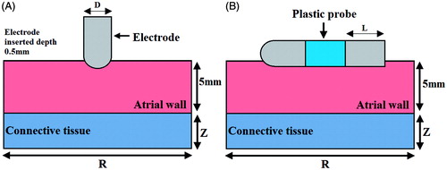
We developed two-dimensional ablation models and used them to represent the three ablation modes. depicts the two models for cardiac ablation (not to scale). To model UiM ablation, the electrode catheter tip was placed perpendicular to the tissue surface, as shown in ; to model BiM and PsM, the multi-electrode catheter, which includes the two active electrodes and a plastic probe, was placed horizontally on the endocardium, as shown in . A fragment of the connective tissue and the atrial wall was considered in the model [Citation13]. Because the atrial wall thickness ranges from 1.2 to 6.5 mm [Citation14], we constructed an atrial wall of thickness 5 mm.
Figure 2. The geometry of the computational model (not to scale). The thickness of the atrial wall is 5 mm. Electrode diameter D = 2.31 mm (7 Fr), electrode length L = 4 mm, insertion depth 0.5 mm and electrode spacing 4 mm.
Model dimensions Z and R were calculated through a sensitivity analysis to avoid boundary effects, and the adequate spatial and temporal resolutions were estimated using convergence tests. The maximal temperature (Tmax) in the tissue after 60 s of ablation was used as the control parameter in the sensitivity and convergence tests. First, a tentative spatial and temporal resolution was considered to determine the appropriate Z and R. We then equally increased Z and R. When the difference in the Tmax between consecutive simulations was less than 0.5%, we considered the dimensions obtained in the preceding step to be adequate. The dimensions were determined separately for each ablation mode. Finally, by using convergence tests and the same control parameter, we determined the adequate spatial and temporal resolution. The values determined were as follows: Z = R = 50 mm, grid size = 0.3 mm, and time step = 0.05 s for BiM and PsM; Z = R = 90 mm, grid size = 0.5 mm, and time step = 0.05 s for UiM.
In this paper we used ANSYS 14.0 for solution and Tecplot 360 EX 2015 for post-processing.
Material characteristics
lists the characteristics of the materials considered in the numerical model [Citation13,Citation15]. The electrical and thermal conductivity of the myocardium was modelled using the temperature-dependent piecewise function [Citation16]. As the temperature increased to less than 100 °C, the electrical conductivity first increased exponentially (1.5%/°C) and then decreased by a factor of 10 000 between 100 °C and 105 °C, whereas the thermal conductivity increased linearly by 1.2%/°C up to 100 °C, following which it remained constant at temperatures exceeding 110 °C.
Table 1. Thermal and electrical characteristics of the elements of the numerical models.
Boundary condition
illustrates the electrical and thermal boundary conditions of the models. In PsM ablation (), a constant zero voltage at the border (mimicking the electrical performance of the dispersive electrode) and two RF voltages with a phase difference of ϕ were applied to the active electrodes. In BiM ablation (), one active electrode was set at Va(t) = A sin ω t, and the other was set at zero voltage to ensure that the electrical currents were forced to flow between the active electrodes. In UiM ablation (), the border of the model was fixed at 0 V (dispersive electrode), and the active electrode was set at Va(t) = A sin ω t.
Figure 3. Electrical and thermal boundary conditions of the models: (A) phase shift mode, (B) bipolar mode and (C) unipolar mode.
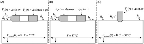
The thermal boundary condition was a constant temperature of T = 37 °C at the border of all three models. The cooling effect produced by blood flow inside the atrium was modelled using two forced thermal convection coefficients – 708 and 3636 W/m2K – for the endocardium–blood (hb) and electrode–blood (he) interfaces, respectively [Citation12].
Assessment of the thermal injury
Although tissue injury is the result of several complex mechanisms, thermal lesions created in the atrial wall can be reasonably approximated using an isotherm of 50 °C [Citation17].
Results
Comparison of the three ablation modes
presents the temperature distributions and the shapes of the lesion in the atrial wall for the three ablation modes. To compare ablation efficacy of three modes under the same electrical and time conditions, the simulation time, the peak value and the frequency of voltage were fixed at 60 s, A = 30 V, and 0.5 Hz, respectively. In the PsM mode, the phase-shift angle of the two RF sources was adjusted from 45–180° in 45° steps. The thermal injury was approximated using the thermal damage borderline: the isotherm of 50 °C, which outlines the width and depth of the lesions. lists the maximum depth and width of the lesions created in the three ablation modes.
Figure 4. Temperature distribution in the tissue after 60 s of RF ablation across 5 mm wall thickness and 4 mm catheter spacing, considering three modes of ablation: (A) unipolar mode, (B) bipolar mode, and (C∼F) phase shift angle ablation PsM-45°, PsM-90°, PsM-135°, PsM-180°. The solid black line is the thermal damage border.
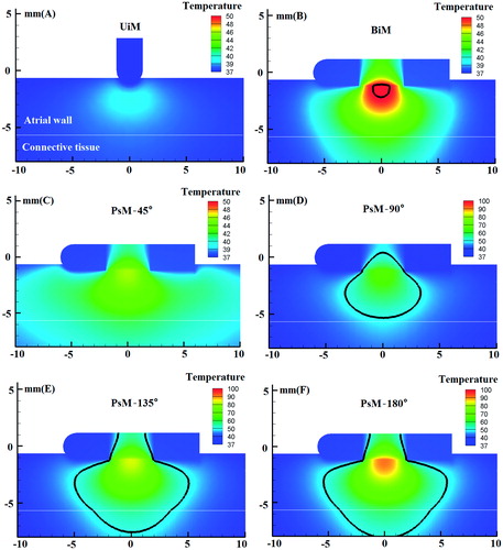
Table 2. Lesion dimensions for three modes of RF ablation: PsM mode, BiM mode and UiM mode.
Because of the low RF voltage (30 V peak value) applied to the active electrode and the blood cooling effect modelled using the forced thermal convection coefficients, UiM ablation failed to create an effective thermal lesion in the atrial wall, and the maximum temperature in the tissue was only 39.55 °C ().
In BiM ablation (), a 2.38-mm wide gap in the tissue surface led to incomplete isolation. The shape of the thermal injury was symmetrical. Among all the modes, BiM ablation yielded the smallest lesion area: the maximum lesion depth and width were only 1.01 and 1.62 mm, respectively.
The lesion dimensions in PsM ablation () differed significantly from those obtained through UiM and BiM ablation. The outstanding finding was that PsM ablation, except PsM-45°, not only created continuous lesions but also created lesions with adequate depth. In PsM-45°, a continuous lesion was not created because the bipolar energy was only a minor part of the total energy and because of the low RF voltage (30 V peak value). However, because the phase-shift was set to 90° at the same low voltage, a continuous and deep lesion was expected because of the simultaneous flowing of bipolar and unipolar currents in the myocardium. As the phase-shift angle varied from 135° to 180°, the proportion of bipolar energy and therefore the maximum lesion depth and width increased, and transmural lesions were generated in the 5-mm thick atrial wall.
Current density distribution in the three ablation modes
During ablation the RF power absorbed by the tissue is directly converted into heat and is proportional to the square of the current density. In this study we also investigated the current density distribution. presents the current density distribution in the three ablation modes at an ablation time of 0.56 μs (ωt = π/2). In this simulation we set the simulation time at 2.22 μs with time step 0.01 μs and the RF frequency was set at 450 kHz for investigating the current density distribution.
Figure 5. Current density distribution in the tissue considering three modes of ablation UiM, BiM and PsM.
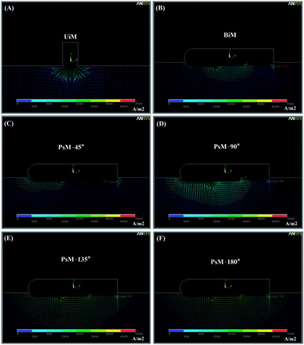
In UiM ablation () the current only flows from the active to the dispersive electrode; therefore the current density is concentrated around the electrode tip. Because a low voltage is applied to the active electrode, the current density around the electrode is low, which leads to the creation of ineffective lesions in this region. Therefore, transmural lesions could not be created through UiM ablation at 30 V peak value of RF voltage.
In BiM ablation the current only flows between the active electrodes (i.e. only bipolar current flows); therefore the current density is concentrated between the electrodes () and is less than those in PsM-90°, PsM-135°, and PsM-180°. Therefore, BiM ablation can create (small and teardrop-shaped) lesions only in the inter-electrode space.
In PsM ablation, unipolar and bipolar currents flow simultaneously in the myocardium because of the phase-shift angle between the RF sources. Therefore, during ablation, current densities are present not only around the catheter space but are distributed in the deeper areas as well. The current density distribution obtained shows that the current density distribution increases with the phase-shift angle (). Through PsM ablation, adequately deep linear lesions were easily generated in a single ablation procedure at a low voltage and an appropriate phase-shift angle.
Discussion
The main objective of this study was to compare the effectiveness of PsM ablation with the effectineness of BiM and UiM ablation in creating a continuous lesion for PVI. The results demonstrated that PsM ablation created larger lesions than do UiM and BiM at a low RF voltage (30 V peak value). Moreover, PsM-135° and PsM-180° created transmural lesions in 5-mm thick atrial walls. Some theoretical studies have concluded that unipolar ablation can create transmural lesions on 1–3-mm thick myocardium but at high ablation voltage and power, for example, at 42.5 V amplitude and 35 W [Citation13,Citation18].
Circumferential ablation around both ipsilateral PVs may be necessary for successfully treating paroxysmal AF and a cornerstone for the ablation of persistent AF supplemented by strategies for further substrate modification, such as creating linear lesions and atrial defragmentation [Citation19,Citation20]. The results of our computer modelling demonstrate that compared with UiM and BiM ablation, PsM ablation can more easily create continuous or linear lesions at low ablation voltage in atrial tissue. Shin et al. [Citation21] clinically assessed the safety and effectiveness of a novel irrigated multi-electrode catheter for PVI. In their study, unipolar energy was delivered simultaneously in the antral region of the PVs from the nMARQ catheter (Biosense Webster, Diamond Bar, CA) to create 10 discrete lesion points [Citation21]. This multichannel RF ablation technique is superior to and is faster than the single ablation technique for PVI, but the orientation of the circular catheter must be changed for complete PVI. By contrast, circumferential lesions can be created easily around PVs with minimal or no catheter movement if phase-shifted RF voltage is applied to the multi-electrode catheter. The results of PsM simulation () reveal that the proportion of bipolar energy increases with the phase-shift angle, and a continuous lesion can be created easily between the electrode spacing. These findings are consistent with those of Wijffels et al., who studied ablation effect by varying the ratios of bipolar energy to create linear lesions in an in vivo porcine experiment [Citation22]. Complications of AF ablation, such as oesophageal fistula and PV stenosis, may occur due to the undesirable extension of thermal damage [Citation23,Citation24]. Therefore, a suitable phase-shift angle is essential in PsM for delivering the energy to the target region without excessive peripheral thermal damage to sensitive areas.
The results demonstrate that the lesion shape can be predicted and thus designed according to the anatomical location. For example, in PsM ablation, the lesion area grows larger as the phase-shift angle increases and the lesion is teardrop-shaped, whereas in BiM ablation the lesion is limited to the region between the electrodes and the lesions are limited in depth and width. In addition, we found that the lesions are symmetrical in all three ablation modes. The lesion area and size were similar in PsM-135° and PsM-180° because the delivered bipolar and unipolar energy is almost identical in these modes.
Study limitations
This study has certain limitations. To compare the effect of ablation in different ablation modes, the same simulation parameters, including ablation time and RF voltage amplitude, were applied to all ablation modes in the finite element analysis; however, this resulted in the tissue temperature not reaching 50 °C in UiM and PsM-45° ablation (). Moreover, we used a non-irrigated catheter to perform cardiac ablation. To create complete transmural lesions or deeper lesions in the thick atria, irrigated catheters should be used [Citation25].
In this study the peak value of RF voltage was fixed at 30 V for the entire ablation duration. However, in clinical application, the power delivery protocol is usually based on a constant temperature algorithm, where a voltage boundary condition on the active electrode is adjusted to maintain a constant electrode tip temperature [Citation26]. Furthermore, studying PsM ablation at different energy modalities, such as damped pulses, non-damped pulses, and constant current amplitude, are expected to yield useful results [Citation27–29].
To obtain comprehensive results, the phase-shift angle setting should be further refined, rather than using only four angles (45°, 90°, 135°, and 180°), as was the case in this study.
The blood flow was modelled using a fixed convection coefficient on the electrode–blood and endocardium–blood interface, which is only representative of a constant blood flow rate, but in clinic applications the blood flow rate varies with the heart diastolic and systolic variables [Citation30]. Therefore, temperature distribution in tissue region varies slightly because of the varying blood flow rate in one cardiac cycle.
Conclusion
The simulation results demonstrate that PsM-90°, PsM-135°, and PsM-180° can create large continuous lesions at 30 V peak value of RF voltage in a single ablation procedure, and that the bipolar voltage can be controlled by varying the phase-shift angle. Therefore, PsM ablation is suitable for complete PVI and linear isolation at the left atrial roof for treating AF.
Disclosure statement
This work received financial support from the Shanghai Engineering Research Centre of Assistive Devices, China, grant no. 15D Z2251700, and the Shanghai Science and Technology Committee Support Program, China, grant no. 13DZ1941802. The authors alone are responsible for the content and writing of the paper.
References
- Wieczorek M, Hoeltgen R, Brueck M, Bandorski D, Akin E, Reza Salili A. Pulmonary vein isolation by duty-cycled bipolar and unipolar antrum ablation using a novel multi-electrode ablation catheter system: First clinical results. J Interv Card Electr 2010;27:23–31.
- Wieczorek M, Hoeltgen R, Tajtaraghi S, Lawrenz W, Lukat M. Pulmonary vein re-isolation for atrial fibrillation using duty-cycled phased radiofrequency ablation: Safety and efficacy of a primary 2:1 bipolar/unipolar ablation mode. J Interv Card Electr 2013;36:55–60.
- Spitzer S, Karolyi L, Weinmann T, Scharfe F, Rämmler C, Otto T, et al. Multielectrode phased radiofrequency ablation compared with point by point ablation for pulmonary vein isolation outcomes in 539 patients. Res Rep Clin Cardiol 2014;5:11–20.
- Bulava A, Hanis J, Sitek D, Osmera O, Karpianus D, Snorek M, et al. Catheter ablation for paroxysmal atrial fibrillation: A randomized comparison between multielectrode catheter and point-by-point ablation. Pacing Clin Electrophysiol 2010;33:1039–46.
- Mulier S, Jiang Y, Wang C, Jamart J, Marchal G, Michel L, et al. Bipolar radiofrequency ablation with four electrodes: Ex vivo liver experiments and finite element method analysis. Influence of inter-electrode distance on coagulation size and geometry. Int J Hyperthermia 2012;28:686–97.
- Berjano EJ. Theoretical modeling for radiofrequency ablation: State-of-the-art and challenges for the future. Biomed Eng Online 2006;5:1–17.
- Lau M, Hu B, Werneth R, Sherman M, Oral H, Morady F, et al. A theoretical and experimental analysis of radiofrequency ablation with a multielectrode, Phased, duty-cycled system. Pacing Clin Electrophysiol 2010;33:1089–100.
- Tungjitkusolmun S, Haemmerich D, Cao H, Tsai JZ, Bin Choy Y, Vorperian VR, et al. Modeling bipolar phase-shifted multielectrode catheter ablation. IEEE Trans Biomed Eng 2002;49:10–17.
- Sherman ML (inventor). RF ablation apparatus and method using unipolar and bipolar techniques. USA patent 2001/0008967.
- Sherman ML (inventor). RF Energy delivery system and method. USA patent 2008/0281322.
- Pennes HH. Analysis of tissue and arterial blood temperatures in the resting human forearm. J Appl Physiol 1948;1:93–122.
- Schutt D, Berjano EJ, Haemmerich D. Effect of electrode thermal conductivity in cardiac radiofrequency catheter ablation: A computational modeling study. Int J Hyperthermia 2009;25:99–107.
- Perez JJ, D’Avila A, Aryana A, Berjano E. Electrical and thermal effects of esophageal temperature probes on radiofrequency catheter ablation of atrial fibrillation: Results from a computational modeling study. J Cardiovasc Electr 2015;26:556–64.
- Ho SY, Sanchez-Quintana D, Cabrera JA, Anderson RH. Anatomy of the left atrium: implications for radiofrequency ablation of atrial fibrillation. J Cardiovasc Electr 1999;10:1525–33.
- Gonzalez-Suarez A, Trujillo M, Koruth J, D'Avila A, Berjano E. Radiofrequency cardiac ablation with catheters placed on opposing sides of the ventricular wall: Computer modelling comparing bipolar and unipolar modes. Int J Hyperthermia 2014;30:372–84.
- Trujillo M, Berjano E. Review of the mathematical functions used to model the temperature dependence of electrical and thermal conductivities of biological tissue in radiofrequency ablation. Int J Hyperthermia 2013;29:590–7.
- Nath S, Lynch C, Whayne JG, Haines DE. Cellular electrophysiological effects of hyperthermia on isolated guinea pig papillary muscle. Implications for catheter ablation. Circulation 1993;88:1826–31.
- Berjano EJ, Hornero F. Thermal-electrical modeling for epicardial atrial radiofrequency ablation. IEEE Trans Biomed Eng 2004;51:1348–57.
- Eitel C, Hindricks G, Sommer P, Gaspar T, Kircher S, Wetzel U, et al. Circumferential pulmonary vein isolation and linear left atrial ablation as a single-catheter technique to achieve bidirectional conduction block: The pace-and-ablate approach. Heart Rhythm 2010;7:157–64.
- O’Neill MD, Wright M, Knecht S, Jais P, Hocini M, Takahashi Y, et al. Long-term follow-up of persistent atrial fibrillation ablation using termination as a procedural endpoint. Eur Heart J 2009;30:1105–12.
- Shin D, Kirmanoglou K, Eickholt C, Schmidt J, Clasen L, Butzbach B, et al. Initial results of using a novel irrigated multielectrode mapping and ablation catheter for pulmonary vein isolation. Heart Rhythm 2014;11:375–83.
- Wijffels MCEF, Van Osterhout M, Boersma LVA, Werneth R, Kunis C, Hu B, et al. Characterization of in vitro and in vivo lesions made by a novel multichannel ablation generator and a circumlinear decapolar ablation catheter. J Cardiovasc Electr 2009;20:1142–8.
- Ravenel JG, McAdams HP. Pulmonary venous infarction after radiofrequency ablation for atrial fibrillation. Am J Roentgenol 2002;178:664–6.
- Martinek M, Bencsik G, Aichinger J, Hassanein S, Schoefl R, Kuchinka P, et al. Esophageal damage during radiofrequency ablation of atrial fibrillation: impact of energy settings, lesion sets, and esophageal visualization. J Cardiovasc Electr 2009;20:726–33.
- Gopalakrishnan J. A mathematical model for irrigated epicardial radiofrequency ablation. Ann Biomed Eng 2002;30:884–93.
- Jain MK, Wolf PD. Temperature-controlled and constant-power radio-frequency ablation: What affects lesion growth? IEEE Trans Biomed Eng 1999;46:1405–12.
- Goldberg SN, Stein MC, Gazelle GS, Sheiman RG, Kruskal JB, Clouse ME. Percutaneous radiofrequency tissue ablation: Optimization of pulsed radiofrequency technique to increase coagulation necrosis. J Vasc Interv Radiol 1999;10:907–16.
- Berjano EJ, Alio JL, Saiz J. Modeling for radio-frequency conductive keratoplasty: implications for the maximum temperature reached in the cornea. Physiol Meas 2005;26:157–72.
- Zhang B, Moser MA, Zhang EM, Luo Y, Zhang W. Numerical analysis of the relationship between the area of target tissue necrosis and the size of target tissue in liver tumours with pulsed radiofrequency ablation. Int J Hyperthermia 2015;31:715–25.
- Tungjitkusolmun S, Vorperian VR, Bhavaraju N, Cao H, Tsai JZ, Webster JG. Guidelines for predicting lesion size at common endocardial locations during radio-frequency ablation. IEEE Trans Biomed Eng 2001;48:194–201.