Abstract
An increasing number of proton therapy facilities are being planned and built at hospital based centers. Most facilities are employing traditional dose delivery methods. A second generation of dose application techniques, based on pencil beam scanning, is slowly being introduced into the commercially available proton therapy systems. New developments in accelerator physics are needed to accommodate and fully exploit these new techniques. At the same time new developments such as the development of small cyclotrons, Dielectric Wall Accelerator (DWA) and laser driven systems, aim for smaller, single room treatment units. In general the benefits of proton therapy could be exploited optimally when achieving a higher level in accuracy, beam energy, beam intensity, safety and system reliability. In this review an overview of the current developments will be given followed by a discussion of upcoming new technologies and needs, like increase of energy, on-line MRI and proton beam splitting for independent uses of treatment rooms.
Proton therapy is becoming increasingly more accepted as a successful treatment in radiation oncology, which goes together with an increase of choices and types of commercial systems. There is also a shift in the type of (potential) customers that would like to employ proton therapy. After the period in which pioneering centers and groups related to nuclear physics accelerator laboratories have been exploiting the possibilities and techniques for proton therapy, today one clearly observes that proton therapy seems to have become mature enough to be applied in centers solely devoted to patient treatments, rather than to technological development.
It is evident that the operational specifications for a proton therapy facility in such centers will be very similar to those of a conventional photon treatment unit. The high investment costs of a proton therapy facility causes new centers to be very demanding with respect to financial aspects (limit of investment costs, reduced operational costs, short delivery times, high capacity/throughput), which leaves little or no room for risky adventures with new technology, not even mentioning the related additional certification procedures. In addition to that, one should not forget that the commercial products have required huge investments by companies who have taken severe risks concerning the necessary technological developments. Therefore the currently available and certified products are, crudely said, rather conservative systems, based on technology developed in the pioneering period of 1970–2000. Currently only a few laboratories and some major centers are developing new techniques. Also it should be mentioned, that most of the companies have underestimated the effort and time needed for development, realization, certification and reliable implementation of proton therapy. Especially the step from “proven technology” to a reliable, safe and certified treatment facility has appeared to be very demanding. Consequently, the burden involved with changing an existing product seems to be so large, that this has led to a reluctance to modify existing equipment accordingly.
Parallel to the currently emerging multi-room facilities employing established technology, there is a clear increase of interest in single room facilities. This is motivated by the much lower financial threshold to start proton therapy at all and potentially encourages the application of proton therapy in more numerous smaller centers, instead of being restricted to a few large multi-room facilities.
Does this maturity of proton therapy mean that major technological developments in proton therapy, once implemented, have almost reached their final goal, i.e. are we approaching the technological limits?
The three major branches of development that are currently being pursued are: 1) improvement of treatment logistics and patient throughput; 2) further development of current beam delivery technology with equipment upgrades in small (affordable) steps and 3) the quest for a “cheap”, stand alone, single treatment room facility. In this review, after a brief overview of the current and emerging dose delivery methods and accelerators, we will discuss several of the developments in the last two branches. In addition to that, we will also point out possible next steps in technology, aimed at a further increase of the benefit and potentials of proton therapy.
Possibilities of different beam delivery techniques
Since the beam emerging from the accelerator is small in diameter and has a narrow Bragg peak, beam spreading systems have been developed. The two major methods to spread the beam in the transverse plane are schematically shown in and are usually referred to as (passive) scattering and (active) pencil beam scanning. Both methods are extensively described in, for example references [Citation1–4].
Figure 1. The two methods to spread the beam in the transverse plane: scattering (left) and pencil beam scanning (right).
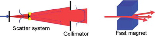
The scattering technique enlarges the beam in the transversal direction by guiding it through one (single scattering) or two (double scattering) pieces of material that deflect the particle trajectories due to multiple Coulomb scattering. The spreading of the Bragg peak over a certain depth is performed by means of a rotating wheel, which is placed in the beam with its rotation axis parallel to the beam direction. The water equivalent thickness of the wheel is similar as the maximum water equivalent extension in depth of the target volume. At the radius where the beam crosses the wheel, the thickness varies along the circumference of the wheel. A rotation of the wheel will thus modulate the range of the protons over the tumor thickness. The distal edge of the spread out Bragg peak is shaped to the distal edge of the target volume by means of a bolus or range compensator. A collimator, mounted just before the patient, defines the transversal shape of the dose distribution. The modulation wheel, collimator and eventual bolus are specific to each angle of beam incidence. Further, it should be noted that the energy modulation and range shifting acts on the total beam cross section, which is designed to coincide with the tumor cross section, projected in the beam direction. Along particle tracks that cross the tumor where it is thinner than the maximum thickness, healthy tissue just in front of the tumor receives the same dose as the tumor [Citation5].
The scattering technique is the most widely employed method. It is relatively robust against organ motion and the beam delivery system can be quite simple in principle.
Pencil beam scanning offers the best flexibility for shaping the dose distribution [Citation5]. Apart from a reduced integral dose with respect to scattered beams, robust field patching as well as intensity modulation are possible [Citation6–8]. Other advantages of pencil beam scanning are the efficient use of the beam (all protons arriving at the gantry entrance are stopped in the target; no losses on collimators) and beam time (no time is lost for changing components like bolus or collimator).
When “painting the dose” with a pencil beam, the lateral displacement of a pencil beam is performed by fast scanning magnets, sometimes together with a orthogonal table motion (e.g. for PSI's Gantry 1 [Citation3]). The depth dimension is covered by changing the beam energy. This can be done by inserting range shifter plates into the beam, just before the patient (such as for Gantry 1 at PSI), or by setting the energy of the beam before it enters the gantry, for example by choosing the appropriate energy at every spill from a synchrotron [Citation4] or with a degrader at the exit of a cyclotron [Citation9]. With the last two methods, the beam line magnets and respective power supplies must be designed to follow these fast changes. In all double scanning systems (i.e. where magnetic scanning is used in both lateral dimensions) the time needed to change energy is the dominating factor that determines the total time needed for volume (re)scanning.
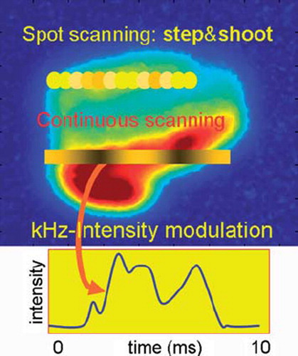
Pencil beam scanning (see ) can be performed by discrete spot scanning (developed and implemented in Gantry 1 at PSI [Citation3], and at GSI, Darmstadt (D) [Citation4]) or in a continuous mode. In discrete mode, the pencil beam is aimed sequentially at a list of locations in the target volume, where the prescribed dose is applied. In contrast, for continuous scanning the beam is swept along a trajectory in the transversal plane and in parallel the beam intensity is varied according to a time-dependent pattern prescribed for this trajectory. This last method is in development at PSI [Citation10,Citation11] but not used in clinical practice yet.
Figure 2. In the “step and shoot” method of pencil beam scanning the beam is aimed at sequential volume elements. When continuous scanning is used, the beam is swept along a contour or a line, while varying the beam intensity.
Spot scanning is being applied now at PSI, HIT in Heidelberg (with carbon ions), RPTC in Munich, MD Anderson Cancer Center in Houston and at the Francis Burr Proton Therapy Center in Boston. In addition, it is being clinically implemented at several facilities currently under construction. The current limitation of this method is its sensitivity to organ motion. Due to the time dependence of the dose application, an interplay with organ motions can occur, giving rise to hot and cold spots in the dose distribution [Citation12]. There are, however, several ways one could deal with this problem [Citation13–17]:
a) Gating: The beam is applied only when the target is at a well defined place, e.g. during a specific phase of the respiration cycle [Citation18,Citation19]. This is dependent on a good correlation between the trigger signal and the real position of the target volume.
b) Fast rescanning: The whole target volume is painted multiple times a minute [Citation10–12] such that motion effects will be averaged out, but at a cost of a larger treated volume. This technique requires increased scanning speeds in order to be effective.
c) Tumor tracking or adaptive scanning: The position and eventual energy of the pencil beam is corrected for a displacement of the target volume on-line [Citation20]. Again, it is critical for this that the relation between the trigger and actual target location is well known, but also that the varying influences of the traversed tissue on the pencil beam characteristics can be modeled.
For each of these approaches there are various possibilities and implementation methods and also combinations of the above methods are possible in principle. Beam gating is already in use in Houston, at HIMAC in Chiba (Japan) and at the Proton Medical Research Center in Tsukuba (Japan). Fast scanning is being developed at PSI and techniques necessary for tumor tracking are being investigated at HIT. Common to all methods is the need for high scanning speeds.
Consequences of new dose application techniques for the accelerator and beam lines
The two commonly used accelerator types are the synchrotron and the cyclotron [Citation21]. The synchrotron is a ring in which particles are injected from a pre-accelerator, and then stored and accelerated to a desired energy. Once this energy has been reached, the particles are slowly extracted and sent to a treatment room. This period of actual beam in the treatment room can typically last several seconds. When not all particles in the ring are used, the remaining particles are decelerated after the extraction has been stopped and dumped. This cycle (spill) is repeated for each required energy.
A cyclotron is one big magnet in which the particles are accelerated to a fixed energy, dependent on the design of the cyclotron. The particles are extracted from the cyclotron and sent to a degrader, in which they are slowed down to the desired energy. The degrader consists of a variable amount of material, usually graphite, and is followed by a collimation system and magnetic analyzer, to select the appropriate energy and energy spread of the beam that is transported to the treatment room. The beam from the cyclotron can be regarded as a continuous stream of particles. The beam intensity must be (and can be) sufficient to compensate the loss of protons in the collimation system behind the degrader. Since beam losses are high [Citation22] in this degrading and collimation process, activation of these components must be dealt with by proper material choices and local shielding.
As experience has demonstrated during several decades and at several centers, both accelerator types are appropriate for passive scattering. For pencil beam scanning, however, application of the synchrotron is currently limited to discrete spot scanning (step and shoot; in some cases without switching the beam off when moving to the next spot). The cyclotron, therefore, seems to be more suitable for advanced scanning techniques due to its continuous and stable beam and its almost unlimited flexibility in beam intensity [Citation21,Citation23]. Furthermore, it has been demonstrated at PSI that changing the beam energy with the degrader can be done in less than 100 ms. This is now routinely exploited for the further development of fast volume scanning. Encouraging possibilities to enable fast pencil beam scanning with volumetric repainting have also been demonstrated [Citation24].
Continuous scanning techniques can be grouped into event driven and time driven methods. In event driven systems the beam intensity is more or less fixed or just taken as it comes from the accelerator. The speed of the pencil beam motion depends on the necessary voxel dose and is eventually corrected for the actual beam intensity. Although one can allow certain beam intensity fluctuations, too large or too fast fluctuations are however difficult to compensate by the speed of the scanning magnets alone.
The time driven method is therefore generally faster. Here the scanning magnets change their fields at a fixed speed and the beam intensity is set as a function of the position of the pencil beam. Rapid (within ms) and accurate (few percent) intensity changes are an essential requirement for fast scanning. As such, unexpected fluctuations or interruptions in the beam intensity or a pulsed beam are not desired.
With a cyclotron, different possibilities for continuous scanning are being investigated. One can vary the arc current of the internal ion source in the cyclotron center, or deflect the beam away from a collimator aperture near the center of the cyclotron. With the latter method, which is pursued at PSI and shown in , beam intensity can be adjusted at a few percent accuracy within 50 μs.
Figure 3. With a fast acting electrostatic deflector plate in the center of the cyclotron the beam can be deflected and partially intercepted by a vertical limiting collimator. The voltage on the plates is used to regulate the beam intensity extracted from the cyclotron [Citation23].
![Figure 3. With a fast acting electrostatic deflector plate in the center of the cyclotron the beam can be deflected and partially intercepted by a vertical limiting collimator. The voltage on the plates is used to regulate the beam intensity extracted from the cyclotron [Citation23].](/cms/asset/ee4c5f05-9a3f-4a1c-a7b1-1ae212d1ceaf/ionc_a_582513_f0003_b.jpg)
For such beam delivery systems, the new dose application techniques impose rigorous changes with respect to the currently used systems. Beam monitoring (intensity and 2/3 D pencil beam position information), fast beam control, fast power supplies and laminated beam line magnets (to allow rapid energy changes), appropriate beam optics (same optics at each energy, so easily scalable magnet settings), a rigorous limitation of the amount of material in the last part of the beam path to obtain a narrow beam (<10 mm FWHM in air at all energies) and an advanced safety system need to be implemented. Since there is little time for a feedback on beam optics errors (beam size or beam position), the beam optics must be designed to be very robust and more or less independent of the beam energy. This facilitates also on-line checks to guarantee a safe dose delivery.
New accelerator developments
Apart from the developments mentioned above, several commercial companies are proposing proton therapy facilities consisting of a single accelerator and beam delivery system. This would then resemble the situation in conventional photon therapy, with independent units at each treatment room. The investment costs of a single room facility are obviously much less than those of a multi-room facility. However, although this would certainly allow an easier (and cheaper) start with proton therapy, if multiple treatment rooms are required, single room solutions are expected to be more expensive.
The required and achieved technological innovations, however, are very interesting and challenging.
Small cyclotrons
Already in 1989 Henry Blosser [Citation25] proposed a single room system, consisting of a small 250 MeV cyclotron, mounted on a rotating gantry. The use of superconducting (SC) magnets would allow an increase of the magnetic field of the cyclotron, so that a smaller machine radius can be achieved. However, since SC magnets are very likely to quench when the coil is deformed, the coil design (stiffness and cooling) is quite challenging. The 30 MeV SC cyclotron at the neutron therapy facility in Detroit [Citation26] demonstrates that it is possible to operate such a cyclotron and its cryogenic equipment in a rotating system.
The first SC-cyclotron of 250 MeV has been based on a NSCL design and has been built by ACCEL (now Varian Medical), in collaboration with PSI [Citation23,Citation27]. Although this cyclotron has not been designed for mounting on a rotating gantry, the possibility of a scale reduction has been demonstrated. With a magnetic field strength of 3.8 T, the outer diameter has been reduced from 5 m in a cyclotron with normal conducting coils to a diameter of 3.5 m. The weight (100 tons) of a SC cyclotron is less than half of one with conventional coils. A resonant extraction scheme is used to obtain an extraction efficiency of 70–80%, which is quite an achievement given the very small turn separation at the extraction energy. A further reduction in size is possible by increasing the magnetic field to 5 T or even 9 T [Citation28,Citation29]. Such proposed cyclotrons have superconducting coils and are very small (<2 m in diameter and about 20 tons), so that mounting on a rotating gantry is possible in principle. At such strong fields, however, several problems need to be solved. First of all, the small dimensions and the small radius of the inner turn that the protons make when leaving the ion source, necessitate small RF-structures and small apertures. Also the orbit separation at extraction is very small, so that high beam losses at extraction are likely, causing activation of the machine. The strong magnetic field highly saturates the iron, so that vertical focusing of the beam in the cyclotron is no longer possible with the techniques normally used in high energy cyclotrons. Therefore very compact cyclotron systems are based on the ‘old’ synchrocyclotron concept, but using more modern RF technology and more sophisticated magnet designs. A synchrocyclotron, however, operates as a pulsed machine with a repetition frequency of typically 1 kHz which limits the applicability of the different pencil beam scanning methods outlined above.
Still River Systems () has built a SC synchrocyclotron mounted on a gantry for a single treatment room facility. The 250 MeV beam is used directly for treatment. Beam energy is adapted with range shifters and modulator wheels and the beam is spread by means of a passive scattering system. There is no beam analysis and there are no magnets in the beam path, which yield compromises on the distal fall off of the dose distribution. Also measures must be taken to reduce dose due to activation and the neutron background delivered to the patient caused by proton interactions with the degrader, modulator and collimator(s). Alternatively, IBA has proposed a single treatment room design, shown in , consisting of a static small synchrocyclotron, which is coupled to a degrader and a dedicated gantry. A beam analysis system is integrated in the beam optics of the two dimensional (2D) scanning gantry.
Figure 4. Compact cyclotron systems from Still River Systems (left) and IBA (right), allowing a proton therapy machine in a single treatment room [Citation28,Citation29].
![Figure 4. Compact cyclotron systems from Still River Systems (left) and IBA (right), allowing a proton therapy machine in a single treatment room [Citation28,Citation29].](/cms/asset/2eb24648-a191-4264-afe8-94450b605d4b/ionc_a_582513_f0004_b.jpg)
Despite the very sophisticated technologies used in the new compact cyclotrons, several compromises are unavoidable. However, it is interesting to evaluate such compromises, and investigate whether this is really a disadvantage in routine operation of a single room facility. For example, due to the lower amount of extracted protons per day in a single treatment room machine, a low extraction efficiency will cause less activation of the machine than it would do in a multi-room facility. On the other hand, the neutron background associated with these beam losses must carefully studied and considered.
New synchrotrons
Ideas for rapid cycling synchrotrons are based on fast extraction schemes: after reaching the energy the full beam is extracted and sent to the treatment room [Citation31]. With a high repetition rate (spills with variable energy at 30 Hz) and strong focusing, a high dose rate scheme with typically 109 protons per bunch has been reached. The machine is not small, however: 10 m × 5 m plus an injector. This scheme is applicable for spot scanning in principle. However, since all protons leave the machine at once, no feedback is possible on the applied dose. This means that the number of protons in the ring, as well as the eventual transmission losses, must be well controlled.
In the Italian TERA project, the design of a compact synchrotron has been studied [Citation30]. The maximum energy of 200 MeV protons is achieved in a ring of 2.2 m diameter, equipped with 4 T dipoles. The ring is injected with 12 MeV negative hydrogen ions, which enter the ring after stripping. The technology of pulsing these magnets with 3.5 ms, 180 kA pulses is also proposed for a compact gantry design. As far as we are aware however, no prototype has been built.
The company PROTOM is proposing a small synchrotron, 6 m in diameter, using a 1 MeV injector. Unlike traditional synchrotrons, the machine does not use sextupole magnets and has a simpler beam injector. The synchrotron can vary the beam energy up to 330 MeV and is small enough to fit into one room. A prototype of the synchrotron is being developed at MIT's Bates Linear Accelerator Center, but to date hardly any detail has been revealed on the performance [Citation32].
At KEK, Japan, [Citation33] a design of a 3.6 m diameter synchrotron has been developed, employing strong (3 T) dipoles. As the magnet saturates heavily at the high excitation level, the maximum current of the dipole is as large as 200 kA for a single turn coil. Supplying this current in a short time (rep. rate <10 Hz) implies that the current from the power supply should be provided by the discharge of a capacitor. Injection is proposed by means of N2 gas or a carbon foil, stripping 2–3 MeV H− ions.
For a synchrotron, typically one has to wait one or two seconds until the next spill reached a different beam energy. But, faster changes of the energy [Citation34] are now being studied at HIMAC. By carefully changing the magnet current and simultaneous deceleration during the slow extraction process, the energy of the extracted beam can be varied within a spill. This would make such synchrotrons more suitable for rapid scanning techniques than traditional designs.
FFAG accelerators
The Fixed Field Alternating Gradient (FFAG) accelerator is essentially a synchrocyclotron which uses a stronger focusing concept, realized by splitting up the magnet in separate sector magnets having an alternating magnetic field [Citation35,Citation38,Citation39]. The sector magnets are designed to include very strong, alternating gradients, which makes the magnet design process very complicated. The RF-frequency varies at a typical repetition rate of up to a kHz, similar to a synchrocyclotron. The cavity and RF-generator are more complicated, however, due to the much stronger electric fields required. The major advantage of FFAG's is the very large acceptance of beam energy and emittance, which is useful in particle physics applications that need reacceleration of reaction products.
FFAG's have been investigated as potential sources for proton or carbon ion therapy for many years [see e.g. Citation36,Citation37,Citation39,Citation41]. For proton therapy, the possible advantages of an FFAG may be its capacity to achieve higher beam intensities than synchrocyclotrons, and the possibility to switch off the RF when the required energy has been achieved which allows extraction at arbitrary energies [Citation37,Citation41]. On the other hand, FFAG's are not small (radius 7–8 m), can have a weight of 100–200 tons and need a ∼10 MeV injection system in addition. This can be a cyclotron [Citation41] or another FFAG [Citation36]. The most promising type of FFAG is complex to design, to build and to operate and also needs complex RF amplifiers. Apart from the rapid energy change (to date not proven in any working machine) it is not yet clear what other advantages the FFAG would offer compared to a cyclotron. However, FFAG-type beam optics, based on very strong alternating gradients, could be of interest for beam transport systems in a gantry [Citation40]. The large momentum acceptance of the optics may prevent the need of changing magnetic fields when changing beam energy. This could speed up the energy modulation considerably.
New accelerator concepts
Dielectric Wall Accelerators.
In linear accelerators, the required length is determined by the maximum achievable strength of the electric RF field. Currently, typical values of 10–20 MV/m can be achieved. Due to various associated structures that need to be included in an accelerating structure, additional length is needed and the effectively obtainable average acceleration field is thus reduced to only a few MV/m. One method to increase the maximum possible electric field is based on application of new types of insulators in accelerating structures. With normal insulators the maximum electric field strength is limited by spark formation. Along the surface of the insulator a spark typically develops due to electrons that repeatedly bombard the surface thus creating an electron avalanche. To obtain a very strong accelerating field one can prevent the development of a spark by shortening the time that the field is present. For conventional insulators a shortening of the high voltage pulse from 1000 ns to 1 ns yields an increase of the surface break down field from 5 to 20 MV/m. Also, new castable dielectrics and a new insulator configuration have pushed this limit up to 100 MV/m [Citation42]. This high gradient insulator (HGI) is made of a stack of floating conductors sandwiched between sheets of insulators. A Dielectric Wall Accelerator (DWA) can be constructed by stacking rings of HGI material and insertion of conducting sheets at frequent intervals along the stack. Each of these sheets is connected to a high voltage switching circuit (Blumleins). When these laser driven switches are closed, an electric field is produced on the inner side of the HGI ring. By successive closing of the switches along the stack, the region of strong electric field is shifted along the stack and protons traveling in phase with this wave will be accelerated through these rings.
During 3 ns pulses, one has achieved this high accelerating field in small HGI samples [Citation43]. This would allow an accelerator design of about 2 m length (+ion source, injection system, scanning magnets, monitoring system) for 200 MeV protons, as shown in . The advantage of such a short linac would be the possibility to build a single room treatment unit by mounting this DWA on a tomotherapy-type of device.
Figure 5. Principle of operation of the Dielectric Wall Accelerator [Citation42]. A traveling high gradient field is created by switching high voltages on electrodes that are sandwiched between High Gradient Insulators.
![Figure 5. Principle of operation of the Dielectric Wall Accelerator [Citation42]. A traveling high gradient field is created by switching high voltages on electrodes that are sandwiched between High Gradient Insulators.](/cms/asset/fad7f4e9-751c-47f3-aa21-732cfc14a653/ionc_a_582513_f0005_b.jpg)
The DWA is pulsed with a repetition frequency of several tens of Hz. Energy variation per pulse can be achieved by using only the appropriate amount of switches.
The key components for a DWA are operating at the limit of current technology: high gradient vacuum insulators, high bulk breakdown strength dielectrics for pulse forming circuits and switches that operate at high voltage. Therefore, in this challenging project there are still many obstacles to overcome [Citation44] and the achieved repetition rate of several tens of Hz is still too slow for scanning. As in all linac based systems, the beam energy depends on the electric field through which the protons are moving. Thus, if this field is not as requested, due for instance to sparks or faulty switches, this will result in an incorrect energy. Given the short pulse times, this cannot be corrected. A very important aspect for proton therapy with respect to the ion source is the safe and accurate control of the large amount of protons per pulse and beam suppression. These topics are still part of the developments of the proton source [Citation45]. In summary, although experience with prototype components has shown that the DWA concept is feasible, experience has shown that substantial additional time is needed until a clinical system has been achieved.
Laser driven accelerators.
Laser and light transmission components can be installed in normal rooms, without the need of heavy concrete shielding. Compared to beam line magnets, the laser and optic components are typically small, light and easy to maintain. This makes the use of lasers to generate energetic proton beams for proton therapy very interesting. Also, scanning the light beam would in principle provide opportunities for pencil beam scanning [Citation46].
Several methods are currently being studied to accelerate protons by means of strong laser pulses [Citation47]. At the moment most experience has been obtained with the TNSA (Target Normal Sheet Acceleration) method [Citation48]. As shown in , a high intensity laser irradiates the front side of a solid target, saturated with hydrogen. A plasma is created due to the energy absorption in the foil and electrons in this plasma emerge from the rear surface. This induces strong electrostatic fields, which accelerate the protons out of the rear surface of the target.
Figure 6. A laser driven accelerator is based on a high power laser pulse, impinging on a target doped with hydrogen atoms. The laser light accelerates the electrons out of the foil, so that an electric field is created that pulls out protons from the foil.
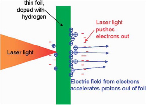
The highest proton energies observed in this method so far are about 20 MeV [Citation49]. This has been achieved with a laser power intensity of 6 × 10¹⁹ W/cm2 and a pulse length of 320 fs. Extrapolation of model calculations to deliver a 200 MeV beam, indicates that the needed laser power would be 1022 W/cm2, at which no experimental results have yet been obtained. The energy spectra of the protons emerging from the foil, however, show a broad continuum [Citation50], which is not suitable for proton therapy. Energy selection systems using dipole magnets and apertures are needed to select protons with the desired energy. In order to prevent this inefficient process, it is proposed [Citation51] to insert a suitably formed scattering material at the location in the analyzing system where the particles are separated in space depending on their energy. Monte Carlo simulations show that configurations can be found that transmit energy spectra that naturally produce spread out Bragg peaks within one laser shot. The method is very sensitive to the initial parameters of the proton beam, however.
An alternative method uses radiation pressure acceleration (RPA) [Citation52]. Here the light pressure of a laser pulse incident on a foil accelerates the whole foil as a plasma slab. Simulations predict that the RPA method can provide higher proton energies and less energy spread than TNSA. However, the RPA method faces even more technological challenges.
Even though the field is developing very fast [Citation53], it is expected that it will still take many years to develop a laser driven medical facility for proton therapy [Citation54,Citation55].
Next steps in the developments of advanced proton therapy
In order to allow a full exploitation of the possibilities of proton therapy, several currently accepted boundaries must be crossed. In this section, we will outline the next steps in the technological developments of proton therapy that we consider of most importance: high accuracy, high energy, high intensity, high safety and high reliability.
Although proton therapy is regarded as a treatment with maximum precision, there are nevertheless some limiting factors as to the precision that can be reached in clinical practice. These can be categorized into: uncertainties in the exact position of the tumor and neighboring critical structures on a day-to-day basis, uncertainties in the exact range of the protons in the patient and limitations in the lateral penumbra of the applied pencil beam. As will be discussed below, these issues can be dealt with by increasing the accuracy of soft tissue imaging and the possibility to increase the proton energy to approximately 350 MeV. A high intensity is a prerequisite to increase the speed of the dose application, which is advantageous for the dose delivery precision in moving targets.
The increase of dose delivery speed immediately raises the issue of safety. The control, monitoring and interruption possibilities need to be based on new concepts and novel instrumentation. Last but not least, the devices must work reliably. A low reliability of the equipment will lead to many interruptions and errors in the dose application process.
High accuracy: On-line soft tissue imaging
Improvement of geometrical accuracy can be achieved with improvement of imaging techniques themselves as well as the use of imaging techniques during the application of the dose. At PSI's Gantry-2 a provision is made for x-ray imaging in a direction parallel to the proton beam [Citation11]. This will yield images similar to the classical “beam's eye view” during proton irradiation, and with on-line fluoroscopy one can verify the location of bony tissue during the treatment.
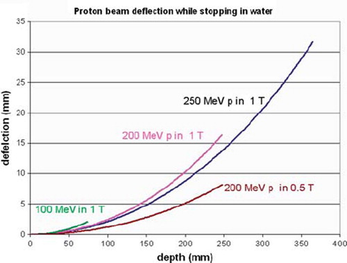
For soft tissues, however, the best imaging modality is MRI. Integration of MRI with photon therapy is being investigated by several groups [Citation56]. This underlines the need for a similar high quality soft tissue imaging for proton therapy, as suggested by Raaymaakers et al. [Citation57]. Since the protons are deflected by the magnetic field of the MRI, its integration has implications for the dose distribution. However, currently achievable “open MRI” magnets provide both an open access to the patient and a sufficient image quality at 0.2–0.5 T. As shown in , in such a field protons of 200 MeV are only deflected by 8 mm at the end of their 25 cm range. This shift is easy to implement in a treatment planning program.
Figure 7. The deflection of a proton beam in a magnetic field, typical for a MRI.
Also on a micrometer scale the dose distribution is hardly changed. The energies of the electrons recoiling after a proton interaction is low (<keV), so that their range is limited. This means that the deflection of the electrons has an almost negligible effect on the dose distribution. It should be investigated, however, whether a slightly larger LET and thus RBE could occur due to the more concentrated dose deposition caused by the curvature (radius <0.1 mm) of the electron paths.
At the technological side the most challenging investigations are on the mutual interactions between the magnetic fields of the MRI and of the beam transport magnets and how these can be compensated, as well as the effect of magnetic fields on beam monitoring systems.
High energy
A facility with the possibility to increase the proton energy to ∼350 MeV offers possibilities for proton radiography at all locations, as well as novel therapeutic opportunities. Proton radiography can be used for range verification of the protons in tissue.
Uncertainty in CT-Hounsfield calibrations as well as possible artifacts in the CT image reconstruction lead to an uncertainty in the calculation of proton range. This uncertainty limits the flexibility in the choice of incident beam angles. Due to the risk of inadvertently over-shooting into critical structures, treatment planners normally avoid using beam angles at which the Bragg peak is supposed to stop just before a critical structure.
In proton radiography the proton stopping power is directly calculated from the measured energy loss of protons (see ) traversing the patient [Citation58–60]. When extending this method with tomography techniques, a three dimensional (3D) stopping power map can be reconstructed [Citation61] with a dose to the patient of only a few mSv. Since for all incident angles the proton range must be larger than the path length through the patient, the usual maximum proton energy of 230–250 MeV must be increased with another 100 MeV.
Figure 8. A proton radiograph of a phantom of the head [Citation58].
![Figure 8. A proton radiograph of a phantom of the head [Citation58].](/cms/asset/4a0499a6-7b06-4e21-a4e4-e3e0072fea71/ionc_a_582513_f0008_b.jpg)
Also for therapy applications high energy can be advantageous. It is a common misconception that, compared to photons, protons generally provide sharper penumbras laterally to the delivered field direction. For many clinical circumstances this is not correct. Although collimated proton beams are somewhat sharper than photons to about 10 cm depth, beyond this depth collimated photon beams will generally provide a sharper penumbra. Although much effort is spent on reducing the phase space of the pencil beam, and sharpening the edges of a scattered beam by collimators, Multiple Coulomb scattering will lead to the larger penumbra at depths beyond 10 cm. This issue can be extremely important when treating around highly sensitive critical organs like the brain stem and/or spinal cord and where one does not trust the exact position of the distal fall-off for reasons discussed before.
High energy protons, however, can be of advantage in this respect. Proton therapy with 1000 MeV is being performed at Petersburg Nuclear Physics Institute in Russia. Their motivation to take advantage of the sharp penumbra [Citation62] is supported by the observation of a negligible increase of the lateral penumbra in tissue. Calculations of the lateral spread of a 350 MeV proton beam, show a transverse penumbra which is almost comparable with the one of carbon ions. In the calculated lateral beam sizes (sigma) of different beams is shown as a function of depth in water. The initial beam size is assumed to have a Gaussian shape, with a sigma of 1 mm. Such a beam size can easily be achieved by a low emittance beam, obtained after proper collimation [Citation63].
Figure 9. The lateral beam size (sigma) of proton beams of different energies as a function of depth in water. When entering the water the beam size has a Gaussian shape with a standard deviation (sigma) of 1 mm. The “virtual” standard deviations of photon beams from a “Gamma knife” and of a “Cyber knife” are indicated as black dots. These are derived from published penumbra data of photon beams [Citation64,Citation65]. The typical width of these beams is about 4 mm and indicated with the dashed vertical arrow.
![Figure 9. The lateral beam size (sigma) of proton beams of different energies as a function of depth in water. When entering the water the beam size has a Gaussian shape with a standard deviation (sigma) of 1 mm. The “virtual” standard deviations of photon beams from a “Gamma knife” and of a “Cyber knife” are indicated as black dots. These are derived from published penumbra data of photon beams [Citation64,Citation65]. The typical width of these beams is about 4 mm and indicated with the dashed vertical arrow.](/cms/asset/1d482c51-4631-438f-83bb-5191854a3e47/ionc_a_582513_f0009_b.jpg)
The ability to irradiate with proton energies of 350 MeV would thus be of great advantage when treating small tumors that are surrounded by multiple, relatively small critical organs (i.e. in the cranium and along the spinal column).
For comparison, lateral penumbras equivalent to about 0.6 mm sigma at 5 cm depths have been reported as being possible with photon beams in the Gamma knife [Citation64], but only after a modification that as far as we know has never been implemented clinically. However, it should anyway be noted that the smallest ‘pencil beam’ size that can be applied with the Gamma knife is 4 mm and this lateral spread adds to this, as indicated with the dashed line in . Similar figures for the Cyber knife result in lateral penumbras equivalent to sigmas of about 1.5 mm [Citation65]. From , it is clear that the additional scatter due to multiple Coulomb scatter for 350 MeV beams at 5 cm depth will only be about 0.2 mm, so considerably smaller than that of the (optimized) Gamma knife and Cyber knife. In addition to that, a small phase space of the proton beam will bring the potential advantage of having initial pencil beams as small as 1 mm (sigma in air).
Of course, protons of 350 MeV will not stop in the patient, but will ‘shoot-through’. Although the dose advantage of a stopped beam will be lost, it should be noted that the integral dose advantage of protons reduces as tumor volume reduces. When normal Bragg peak irradiations are performed, for example to treat small intracranial or paraspinal tumors, there may be no great advantage from protons through integral dose alone. However, if the lateral penumbra around these small tumors is improved by using higher energies, there could be great advantage in more precise conformation of the dose.
Currently, at PSI plans are being developed to add a linear accelerator to the existing beam transport system, in which the energy of the protons could be boosted from 250 up to 350 MeV. As with the LIBO proposal [Citation66], the final energy can be regulated by switching the amount of active cavities. Of course, the eventual use of 350 MeV protons will have implications on gantry design. However, the ongoing developments of superconducting magnets may be helpful in this respect.
High intensity
A disadvantage of the use of a degrader is the large fraction of lost beam [Citation22]. The most straight forward method is to compensate this by increasing the beam intensity from the cyclotron. At PSI the extracted beam intensity is 150 nA for Gantry-1, 200–500 nA for Gantry-2 and raised to 800 nA for the eye treatments at 70 MeV. But there are also other advantages of a high intensity. For the dose application, a high intensity offers opportunities for multiple volumetric painting. Also a high speed in combination with accurate target position monitoring will enable a more precise dose application in case of moving targets. At PSI this development is clearly visible in the increase of scanning speed. At Gantry-1 (20 years old) this is on average about 50 Hz, at Gantry-2 it will be about 200 Hz for discrete spot scanning and equivalent to about 1 kHz for line scanning. A reduction of treatment time with at least a factor 5 is therefore expected.
A very big advantage with respect to the efficient utilization of a multiple room facility would be the situation where the treatment rooms are independent from each other, i.e. that one does not have to wait with the irradiation until the treatment in another room has finished. This can be avoided when a high intensity beam is continuously available, as possible with a cyclotron. The beam for a certain area is split off from the rest of the beam, degraded and analyzed separately and used for treatment. Intensity control can be done with a fast sweeper magnet in the split off beam, followed by a collimator. Recent developments in gantry design [Citation29] indicate the possibility of integrating a beam analyzing system on the gantry. Beam splitting requires a facility with a slightly different layout compared to the current standard layout and also the investment costs will be a little bit higher, due to the multiple degraders and additional shielding requirements. However, in a facility of four rooms as shown in , this could enable an increase of the throughput by a factor 2 and the optimal number of rooms per facility could also be higher than the currently accepted optimum of three to four. The cyclotron must however be capable of delivering a proton beam of 1–1.5 μA continuously during the treatment day. At such high continuous beam currents, high extraction efficiency is of utmost importance.
Figure 10. A possible layout of a proton therapy system using a continuous high intensity beam, which is split at septum magnets following defocusing quadrupole magnets. Kicker magnets controlling beam on/off and intensity per gantry room are indicated with “k”. Each treatment room has its own degrader and beam analysis system (“Energy Selection System”, ESS, possibly to be included in the gantry optics). This method allows complete independence of the treatment rooms with respect to each other. In this respect the experience until 2005 at PSI has shown that a safe patient treatment operation is possible with a beam that has been split off from 2 mA proton beam of 590 MeV [Citation3].
![Figure 10. A possible layout of a proton therapy system using a continuous high intensity beam, which is split at septum magnets following defocusing quadrupole magnets. Kicker magnets controlling beam on/off and intensity per gantry room are indicated with “k”. Each treatment room has its own degrader and beam analysis system (“Energy Selection System”, ESS, possibly to be included in the gantry optics). This method allows complete independence of the treatment rooms with respect to each other. In this respect the experience until 2005 at PSI has shown that a safe patient treatment operation is possible with a beam that has been split off from 2 mA proton beam of 590 MeV [Citation3].](/cms/asset/9eefdada-a2e1-459a-a386-f66e0c0ffcc5/ionc_a_582513_f0010_b.jpg)
High safety
The increase of dose rate, fast switching between treatment rooms and fast energy switching has increased the need for more inherent safe systems. Beam transport optics can be designed such that the beam optics is not dependent on beam energy, and that small errors do not immediately lead to dangerous situations. The concept currently used at PSI, for example, has decoupled beam optics at the entrance of each area (or gantry). At this location a collimator is located, as well as some beam diagnostics. A misalignment of the beam yields a lower dose rate only, but no displacement of the beam spot at the gantry isocenter. Also wrong beam energies or other errors are recognized by transmission measurements.
The high dose rates and dynamic dose application methods require fast, accurate and position sensitive monitoring systems in the nozzle. These requirements are often in conflict with specified simplicity and the small amount of material allowed in the beam path. In general much more need of redundancy is required to guarantee a safe dose delivery.
High reliability
High reliability is, of course, a specification that one would always like to be fulfilled. Working with many interruptions is not desirable for many reasons. The proposed high dose rates, however, impose an additional reason to have a system with high reliability. In case of failures, the safety systems can interrupt the beam and bring the machine in a safe state. The speed of the delivery process may yield an increase in the uncertainty in the actually given last dose and in the location of this last dose. In order to minimize the consequences of such possible errors, the probability that they occur should be low, i.e. the reliability of the machine should be high.
A high level of safety can often lead to an increase in the frequency of beam trips, due to interlock signals from safety systems. Setting too strict limits, will lead to over-reactions of the safety system. Apart from unwanted excessive downtime of the machine having a potential impact on patient throughput, an undesirable or even dangerous situation can occur when such frequently occurring interlock signals are bypassed. Although bypassing of interlock signals is never appreciated or intended, history has shown in general that frequent quick resets or neglecting of recurring unserious errors can lead to delivery errors. Therefore an inherent safe and reliable system design is the only way to allow an increase in complexity of the proton therapy treatments.
Conclusions
On a short term, the currently available proton therapy systems can still be improved considerably by extending their possibilities to fast pencil beam scanning. Parallel to these natural improvements, new accelerator concepts are being developed, aiming to reduce system size, such that a proton therapy machine could fit into a single treatment room. Two such initiatives based on small cyclotrons are claimed to be close to implementation. Other developments are not so well documented yet (e.g. small synchrotron), or are in a stage where there is still a long way to go from the proof of principle to a clinical system (e.g. DWA) or are still in a fundamental research phase (e.g. laser driven systems).
All new developments are often presented as big steps forward, solving “all” problems of proton therapy, stressing the advantages (size, costs) and promise unrealistic optimism in the time it will take for clinical implementation.
These optimistic views may be necessary to obtain funding of these interesting and necessary developments, but as a potential user, one should be very critical about such new developments and cheap solutions. One should ask whether the new systems provide at least the same quality as we have now and, if yes, what advantages the new systems would bring and when they can realistically be implemented in routine clinical use. Until now the step from “proven technology” to reliable and safe operation with a certified system has proven to be largely underestimated.
We have listed “five highs” that could give a boost in the possibilities and quality of proton therapy on a longer term. These and the above mentioned developments indicate that proton therapy technology is an evolving discipline and that many interesting developments are in the pipeline.
Declaration of interest: The authors report no conflicts of interest. The authors alone are responsible for the content and writing of the paper.
Related Research Data
References
- Koehler AM, Schneider RJ, Sisterson JM. Flattening of proton dose distributions for large field radiotherapy Med Phys 1977;4:297–301.
- Gottschalk B. Passive beam spreading in proton radiation therapy. Available from: http://huhepl.harvard.edu/∼gottschalk/
- Pedroni E, Bacher E, Blattmann H, Boehringer T, Coray A, Lomax AJ. The 200 MeV proton therapy project at PSI: Conceptual design and practical realization. Med Phys 1995; 22:37–53.
- Haberer T, Becher W, Schardt D, Kraft G. Magnetic scanning system for heavy ion therapy. Nucl Instr Meth A 1993; 330:296–305.
- Goitein M, Lomax AJ, Pedroni ES. Treating cancer with protons. Phys Today 2002;55:45–50.
- Lomax AJ. Intensity modulated methods for proton therapy. Phys Med Biol 1999;44:185–205.
- Lomax AJ, Boehringer T, Coray A, Egger E, Goitein G, Grossmann M. Intensity modulated proton therapy: A clinical example. Med Phys 2001;28:317–24.
- Lomax AJ, Pedroni E, Rutz HP, Goitein G. The clinical potential of intensity modulated proton therapy. Z Med Phys 2004;14:147–52.
- Schippers JM, Dölling R, Duppich J, Goitein G, Jermann M, Mezger A, . The SC 250 MeV cyclotron and beam lines of PSI's new protontherapy facility PROSCAN. Nucl Instr Meth B 2007;261:773–6.
- Schippers JM. Scanning techniques for cancer therapy with hadrons – a domain of cyclotrons. Proceedings of the 19th International Conference on cyclotrons and their applications; 2010 Sep 6–10; Lanzhou, China. 2010.
- Pedroni E, Bearpark R, Böhringer T, Coray A, Duppich J, Fors S, . The PSI Gantry 2: A second generation proton scanning gantry. Z Med Phys 2004;14:25–34.
- Phillips MH, Pedroni E, Blattmann H, Boehringer T, Coray A, Scheib S. Effects of respiratory motion on dose uniformity with a charged particle scanning method. Phys Med Biol 1992;37:223–33.
- Lomax AJ. Intensity modulated proton therapy and its sensitivity to treatment uncertainties 2: The potential effects of inter-fraction and inter-field motions. Phys Med Biol 2008;53:1043–56.
- Seco J, Robertson D, Trofimov A, Pagansetti H. Breathing interplay effects during proton beam scanning: Simulation and statistical analysis. Phys Med Biol 2009;54:N283–94.
- Lambert J, Suchowerska N, McKenzie DR, Jackson M. Intrafractional motion during proton beam therapy. Phys Med Biol 2005;50:4853–62.
- Paganetti H, Jiang H, Trofimov A. 4D Monte Carlo simulation of proton beam scanning: Modelling of variations in time and space to study the interplay between scanning pattern and time-dependent patient geometry. Phys Med Biol 2005;50: 983–90.
- van de Water S, Kreuger R, Zenklusen S, Hug EB, Lomax AJ. Tumour tracking with scanned proton beams: Assessing the accuracy and practicalities. Phys Med Biol 2009;54: 6549–63.
- Hiramoto K, Umezawa M, Saito K, Tootake S, Nishiuchi H, Hara S, . The synchrotron and its related technology for ion beam therapy. Nucl Instr Meth B 2007;261:786–90.
- Yamada S, Honma T, Kanazawa M, Kitagawa A, Kouda S, Kumada M, . HIMAC and medical accelerator projects in Japan. Proceedings of the Asian Particle Accelerator Conference; 1998 Mar 23–27; Tsukuba, Japan. 885–9.
- Saito N, Bert C, Chaudri N, Gemmel A, Schardt D, Durante M, . Speed and accuracy of a beam tracking system for treatment of moving targets with scanned ion beams. Phys Med Biol 2009;54:4849–62.
- Schippers JM. Beam delivery systems for particle radiation therapy. Rev Acc Sci Tech 2009;2:179–200.
- van Goethem MJ, van der Meer R, Reist HW, Schippers JM. Geant4 simulations of proton beam transport through a carbon or beryllium degrader and following beam line. Phys Med Biol 2009;54:5831–46.
- Schippers JM, Anicic D, Dölling R, Mezger A, Pedroni E, Stamsnijder L . Proceedings of the 18th International Conference on cyclotrons and their applications; 2007 Oct 1–5; Catania, Italy. Rifuggiato D, Piazza LAC. Catania, Italy: INFN-LNS; 2008. 300–2.
- Hug E, Timmermann B, Pedroni E, Meer D. Converging missions on cancer treatment at the Center for Proton Therapy (CPT). PSI, Villigen; 2008, 56–8.
- Blosser H, Burleigh R, Johnson D, Kuo T, Marti F, Vincent J, . Medical accelerator projects at Michigan state university. Proceedings of Particle Accelerator Conference, Chicago (Ill), USA, March 20–23, 1989. Accelerator Science and Technology. IEEE 1989;2:742–6.
- Maughan RL, Powers WE, Blosser HG. A superconducting cyclotron for neutron radiation therapy. Med Phys 1994; 21:779–85.
- Schillo M, Geisler A, Hobl A, Klein HU, Krischel D, Meyer-Reumers M, . Compact superconducting 250 MeV proton cyclotron for the PSI PROSCAN Proton Therapy Project. Proceedings of the 16th International Conference on cyclotrons and their applications; East Lansing (Mi), USA, May 13–17, 2001. 37–9.
- Still River Systems, Littleton (MA), USA, 2011. Available from: http://www.nim.nih.gov/bsd/uniform_requirements.html.
- IBA, Louvain la Neauve, Belgium, 2011. Available from: http://www.iba-protontherapy.com/proteus-one.
- Picardi L, Ronsivalle C, Vignati A, Silvestrov G, Vsevolozskhaya T, Bartolini R, . Preliminary design of a very compact protosynchrotron for proton therapy. Proceedings of the European Particle Accelerator Conference; London, Great Britain, June 27-July 1, 1994. 2607–9.
- Peggs S, Barton D, Beebe-Wang J, Cardona J, Brennan M, Fischer W, . The rapid cycling medical synchrotron, RCMS. Proceedings of the European Particle Accelerator Conference; 2002. 2754–6.
- Protvino (Moscow), Russia, PROTOM, 2010. Available from: http://www.protom.ru/
- Endo K, Egawa K, Fang Z, Mizobata M, Teramoto A. Development of high field dipole and high current pulse power supply for compact proton. Proceedings of the European Particle Accelerator Conference; Paris, France, June 3–7, 2002. 1071–3.
- Iwata Y, Furukawa T, Mizushima K, Noda K, Shirai T, Takeshita E, . Multiple-energy operation with Quasi-DC extension of flattops at HIMAC. Proceedings of the 1st International Particle Accelerator Conference: IPAC'10; 2010 May 23–28; Kyoto, Japan. MOPEA008 79–81.
- Symon KR, Kerst DW, Jones LW, Laslett LJ, Terwilliger KM. Fixed-field alternating-gradient particle accelerators. Phys Rev 1956;103:1837–59.
- Keil E, Trbojevic D, Sessler AM. Fixed field alternating gradient accelerators (FFAG) for fast hadron cancer therapy. Proceedings of Particle Accelerator Conference; 2005 May; Knoxville, TN, USA. 1667–9.
- Antoine S, Autin B, Beeckman W, Collot J, Conjat M, Forest F, . Principle design of a protontherapy, rapid-cycling, variable energy spiral FFAG. Nucl Instr Meth A 2009; 602:293–305.
- Craddock MK, Symon KR. Fixed field alternating gradient accelerators. Rev Acc Sci Tech 2008;1:65–97.
- Trbojevic D. FFAGs as accelerators and beam delivery devices for ion cancer therapy. Rev Acc Sci Tech 2009;2:229–51.
- Trbojevic D, Gupta R, Parker B, Keil E, Sessler AM. Superconducting non-scaling FFAG gantry for carbon/proton cancer therapy. Proceedings of Particle Accelerator Conference; 2007. 3199–201.
- Peach K, Cobb J, Yokoi T, Gardner I, Edgecock R, Poole M, . PAMELA – A model for an FFAG based hadron therapy machine. Proceedings of Particle Accelerator Conference; Albuequerque (NM), USA, June 25–29, 2007 THPMN076. 2880–2.
- Caporaso GJ, Sampayan S, Chen Y-J, Harris J, Hawkins S, Holmes C, . Compact accelerator concept for proton therapy. Nucl Instr Meth B 2007;261:777.
- Caporaso GJ, Chen Y-J, Sampayan S, Akana G, Anaya R, Blackfield D, . Status of the Dielectric Wall Accelerator. Proceedings of Particle Accelerator Conference; Vancouver (BC), Canada, May 4–8, 2009 TH3GAI02.
- Caporaso GJ, Chen Y-J, Sampayan S. The Dielectric Wall Accelerator. Rev Acc Sci Tech 2009;2:253–63.
- Chen Y-J, Guethlein G, Caporaso G, Sampayan S, Akana G, Anaya R, . Compact proton injector and first accelerator system test for compact proton dielectric wall cancer. Proceedings of Particle Accelerator Conference; Vancouver (BC), Canada, May 4–8, 2009 TU6PFP094.
- Ma CM, Veltchev I, Fourkal E, Li JS, Luo W, Fan J, . Development of a laser-driven proton accelerator for cancer therapy. Laser Phys 2006;16:639–46.
- Tajima T, Habs D, Yan X. Laser acceleration of ions for radiation therapy. Rev Acc Sci Tech 2009;2:201–28.
- Wilks SC, Langdon AB, Cowan TE, Roth M, Singh M, Hatchett S, . Energetic proton generation in ultra-intense laser–solid interactions. Phys Plasmas 2001;8:542–9.
- Fuchs J, Antici P, d'Humières E, Lefebvre E, Borghesi M, Brambrink E, . Laser-driven proton scaling laws and new paths towards energy increase. Nature Phys 2006;2:48–54.
- Malka V, Fritzler S, Grillon G, Chambaret J-P, Antonetti A, Hulin D, . Practicability of protontherapy using compact laser systems. Med Phys 2004;31:1587–92.
- Schell S, Wilkins JJ. Modifying proton fluence spectra to generate spread-out Bragg peaks with laser accelerated proton beams. Phys Med Biol 2009;54:N459–66.
- Robinson APL, Zepf M, Kar S, Evans RG, Bellei C. Radiation pressure acceleration of thin foils with circularly polarized laser pulses. New J Phys 2008;10:013021, 1–13.
- Ledingham K. Desktop accelerators going up? Nature Phys 2006;2:11–2.
- Ma CM, Maughan RL. Point/Counterpoint. Within the next decade conventional cyclotrons for proton radiotherapy will become obsolete and replaced by far less expensive machines using compact laser systems for the acceleration of the protons. Med Phys 2006;33:571–3.
- Linz U, Alonso J. What will it take for laser driven proton accelerators to be applied to tumor therapy? Phys Rev ST Accel Beams 2007;10:094801–1:8.
- Lagendijk JJ, Raaymakers B, van der Heide U, Bakker C, Raaijmakers A, Vulpen M, . In Room Magnetic Resonance Imaging Guided Radiotherapy (MRIgRT). Med Phys 2005;32:2067.
- Raaymakers BW, Raaijmakers AJE, Lagendijk JJW. Feasibility of MRI guided proton therapy: Magnetic field dose effects. Phys Med Biol 2008;53:5615–22.
- Schneider U, Pedroni E. Proton radiography as a tool for quality control in proton therapy. Med Phys 1995;22:353.
- Pemler P, Besserer J, de Boer J, Dellert M, Gahn C, Moosburger M, . A detector system for proton radiography on the gantry of the Paul-Scherrer-Institute. Nucl Instr Meth A 1999;432:483–95.
- Mumot M, Algranati C, Hartmann M, Schippers JM, Hug E, Lomax AJ. Proton range verification using a range probe: Definition of concept and initial analysis. Phys Med Biol 2010;55:4771–82.
- Schulte RW, Bashkirov V, Loss Klock MC, Li T, Wroe AJ. Density resolution of proton computed tomography. Med Phys 2005;32:1035–46.
- Abrosimov NK, Yu A, Gavrikov EM, Ivanov DL, Karlin AV, Khanzadeev NN, . 1000 MeV proton beam therapy facility at Petersburg Nuclear Physics Institute Synchrocyclotron. J Phys: Conf Ser 2006;41:424–32.
- Van Luijk P, Bijl HP, Coppes RP, van der Kogel AJ, Konings AWT, Pikkemaat JA, . Techniques for precision irradiation of the lateral half of the rat cervical spinal cord using 150 MeV protons. Phys Med Biol 2001;46:2857–71.
- Guerrero M, Allen Li X, Ma L. A technique to sharpen the beam penumbra for Gamma Knife radiosurgery. Phys Med Biol 2003;48:1843–53.
- Wilcox EE, Daskalov GM. Evaluation of GAFCHROMIC EBT film for CyberKnife dosimetry. Med Phys 2007; 34:1967.
- Amaldi U, Braccini S, Puggioni P. High frequency linacs for hadrontherapy. Rev Acc Sci Tech 2009;2:111–31.