Abstract
Background. Tumor motion during radiotherapy delivery can substantially deteriorate the target dose distribution. A promising method to overcome this problem is dynamic multi-leaf collimator (DMLC) tracking. The purpose of this phantom study was to integrate a wired electromagnetic (EM) transponder localization system with DMLC tracking and to investigate the geometric accuracy of the integrated system. Material and methods. DMLC tracking experiments were performed on a Trilogy accelerator with a prototype DMLC tracking system. A wired implantable EM transponder was mounted on a motion stage with a 3 mm tungsten sphere used for target visualization in continuous portal images. The three dimensional (3D) transponder position signal was used for DMLC aperture adaption. The motion stage was programmed to reproduce eight representative patient-measured trajectories for prostate and for lung tumors. The tracking system latency was determined and prediction was used for the lung tumor trajectories to account for the latency. For each trajectory, three conformal fields with a 10 cm circular MLC aperture and 72 s treatment duration were delivered: (1) a 358° arc field; (2) an anterior static field; and (3) a lateral static field. The tracking error was measured as the difference between the marker position and the MLC aperture in the portal images. Results. The tracking system latency was 140 ms. The mean root-mean-square (rms) of the 3D transponder localization error was 0.53/0.54 mm for prostate/lung tumor trajectories. The mean rms of the two dimensional (2D) tracking error was 0.69 mm (prostate) and 0.98 mm (lung tumors) with tracking and 3.4 mm (prostate) and 5.3 mm (lung tumors) without tracking. Conclusions. DMLC tracking was integrated with a wired EM transponder localization system and investigated for arc and static field delivery. The system provides sub-mm geometrical errors for most trajectories.
Intrafraction tumor motion in radiotherapy (RT) can occur from respiratory, cardiac and gastrointestinal functions as well as from other patient movements [Citation1]. Tumor motion during beam delivery can substantially deteriorate the target dose distribution as the tumor moves with respect to the beam [Citation2,Citation3]. This presents a significant challenge in treating moving tumors, particularly for hypofractionation, where possible inaccuracies in dose delivery are critical due to the low number of fractions, or for intensity modulated radiotherapy (IMRT), where the beam is specifically shaped to irradiate as little healthy tissue as possible. Several methods have been developed to account for tumor motion during RT; including motion encompassing margins, gated beam delivery and real-time tumor tracking.
A promising method to overcome the problem of tumor motion is real-time tumor tracking, i.e. continuous realignment of the treatment beam and the tumor. Until now, only the robotic Cyberknife system (Accuray Inc., Sunnyvale, CA, USA) is used clinically for tracking [Citation4], but for conventional linear accelerators both couch tracking [Citation5] and dynamic multi-leaf collimator (DMLC) tracking [Citation6–10] have been investigated in phantom studies. Tumor tracking inherently has some latency due to signaling and processing of data, but minimizing latency is imperative to yield good results [Citation6,Citation11]. This is true whether prediction of the tumor motion is used in the tracking procedure (for repetitive motion trajectories, e.g. respiratory tumors) or not (for singular motion trajectories, e.g. prostate) [Citation6]. Tracking requires real-time monitoring of internal organ movements. This has been done by x-ray imaging [Citation7,Citation8,Citation12] and the electromagnetic (EM) transponder system Calypso [Citation13–15]. As of late, wired EM transponder systems are emerging [Citation16,Citation17], that have the potential advantage of being removable post-treatment. In this phantom study we integrate a novel wired implantable EM transponder localization system (RayPilot, Micropos Medical AB, Gothenburg, Sweden) with DMLC tracking and examine the latency and the geometric accuracy of the integrated system.
Material and methods
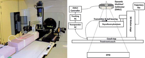
DMLC tracking experiments were performed on a Trilogy accelerator with a PortalVision AS1000 portal imager (Varian Medical Systems, Palo Alto, CA, USA) with a prototype DMLC tracking system. The field aperture was circular with 10 cm diameter and DMLC leaves aligned in the cranio-caudal (CC) direction. Doses of 600 MU (static gantry treatments) or 720 MU (arc treatments) were delivered in 72 s. The beam energy was 6 MV. A wired implantable EM transponder (RayPilot) was used for localization measurement in three dimensions. The EM transponder consists of three parts: a wired transmitter to be placed in the region of interest (ROI), a receiving system placed on the couch, and software that outputs the real-time transmitter position. The EM transmitter was placed on a Styrofoam phantom (see for a visual representation of the experiment setup). The transmitter signal was received by antennae arrays in the table top at a frequency of 30 Hz and was used to generate a three dimensional (3D) transmitter position that was used for DMLC aperture adaption. A tungsten sphere 3 mm in diameter was placed at the tip of the EM transmitter for target visualization in MV portal images, which were acquired continuously at 7.5 Hz by the portal imager system during the experiments. The latency of the integrated tracking system was determined as the time lag between the tungsten sphere motion and the DMLC aperture motion in the portal images for a sinusoidal motion [Citation13].
Figure 1. Left: Photo showing the experiment setup. The tungsten sphere at the tip of the electromagnetic transmitter is marked by the red laser X. Right: Schematic showing the experiment setup. A trajectory file is uploaded to the motion stage on which is mounted a Styrofoam phantom with the electromagnetic transmitter on top. A tracking PC receives the position localization signal from the transponder software and instructs the DMLC to adjust accordingly.
The focus of this study concentrated on prostate and lung tumor motion. Prostate motion was chosen because significant complex motion is seen in some cases [Citation18], and the RayPilot system is initially certified (CE) for clinical RT of the prostate. Although clinical use of the wired transmitter as an implant marker for lung tumors is not likely, lung tumor motions were chosen because they show large motion magnitudes and high frequencies of repetitive pattern, which allowed us to performance test the integrated system with motion predictive tracking as well. The phantom was mounted on a motion stage [Citation19] that was programmed to reproduce four representative lung trajectories and four representative prostate trajectories. The same trajectories have been used in previous studies of DMLC tracking [Citation18], and were carefully selected for their respective difference, motion magnitude and complexity in a database with 160 thoracic abdominal trajectories (46 patients) estimated by a Cyberknife Synchrony system at Georgetown University Hospital, Washington DC [Citation20] and a database with 548 prostate trajectories (17 patients) measured by Calypso EM transponders at M. D. Anderson Cancer Center, Orlando, Florida [Citation21]. For each trajectory, three treatments of 72 s duration were delivered: (1) a 358° arc field; (2) an anterior static field; and (3) a lateral static field.
The DMLC tracking procedure consisted of: (1) a 3D localization estimation signal from the EM transponder; (2) modified linear adaptive filter prediction [Citation22] to account for the tracking system latency (lung only); and (3) adjustment of the DMLC aperture to the resulting estimated 3D target position. The motion prediction algorithm used the last 20 s of measured 3D position as reference data. Thus, for the lung trajectories, localization signals from the EM transponder were acquired for at least 20 s before treatment in order to acquire sufficient training data for motion predictive tracking. No prediction was used for prostate. At least 4 s of additional static transmitter localization data from the EM transponder was generated prior to start of the motion stage during the lung tumor trajectory experiments. The range and spread of the data represent a measure of the stability of the system over the duration of these lung experiments. During all experiments the tracking program generated a log file with the real-time target position as measured by the EM transponder and, for lung tumor trajectories, the predicted target position at beam correction, i.e. accounting for the measured system latency.
Off-line analysis of the transponder localization accuracy
After the experiments, the EM transponder position measurements were compared with the input trajectories for the motion phantom, which were assumed to be the actual target positions. The real-time target position localization error at the time of localization was calculated as the difference between the actual target position and the simultaneous transmitter measurement. For each treatment the root-mean-square (rms) of this error was calculated in the 3D room coordinate system. This position estimation error reflects the localization accuracy of the wired EM transponder system. The target position estimation error at the time of beam correction was calculated as the difference between the actual target position and the estimated target position at the time the DMLC leaves find their new position (i.e. at the time of localization plus latency) either with prediction (for lung tumor trajectories) or without (for prostate). The rms of the 3D target position estimation error at the time of beam correction was determined for each treatment. This target position estimation error reflects the accuracy of the target localization including uncertainties from both the EM transponder and the tracking latency. For the lung tumor trajectories this position estimation error also includes the uncertainty of the prediction algorithm.
Off-line analysis of the tracking accuracy
Continuous portal images were acquired at 7.5 Hz during the experiments in the beam-on periods for independent recording of the tracking process in beam's eye view (BEV) of the treatment beam. After the experiments, the tungsten sphere at the tip of the EM transmitter and the DMLC aperture were segmented in each portal image [Citation23]. The tracking error was calculated for each portal image as the 2D positional difference between the actual target position and the center of the circular DMLC aperture. This tracking error measures the actual 2D beam-target error of the treatment, with all uncertainties combined. The rms of the tracking error was determined for each treatment. The 2D beam-target error as it would have been without tracking was calculated for each portal image as the 2D positional difference between the actual target position and the center of the aperture for a stationary reference field. The rms of the beam-target error without tracking was determined for each treatment.
Results
The stability of the EM transponder during all 12 lung tumor trajectory experiments is shown in . Over a period of time of 60 min, the EM transponder showed very little drift (linear displacement). The measured position of the EM transponder had a very small general drift in the left-right (LR) direction from + 0.2 mm at the beginning of the experiments to -0.1 mm at the end of experiments. The CC and anterior-posterior (AP) directions showed no drift from the start of the experiments to the end of the experiments but were distributed about mean displacements of -0.04 mm and 0.13 mm, respectively. The CC direction was the most accurate with a rms of 0.062 mm while the AP direction displayed most fluctuation with a rms of 0.17 mm.
Figure 2. Stability of the transponder signal. The vertical bars show the range of measured displacement for a static motion stage in a 4 s period prior to all lung tumor trajectory experiments. The 12 vertical bars correspond to the four lung tumor trajectories for each of the three treatment type experiments; arc, static AP, and static lateral.
The tracking system latency was found to be 140 ms.
Localization accuracy of the EM transponder
summarizes the mean rms position estimation errors. shows an example of 3D geometric accuracy for one of the experiments with lung tumor trajectories. The 3D position localization measurements of the EM transponder are seen to be very well correlated with the actual phantom motion. The mean rms of the 3D transponder localization error at the time of localization was 0.53 mm for prostate trajectories and 0.54 mm for lung tumor trajectories. At the time of beam correction, the 140 ms latency had enlarged the mean rms of the localization error to 0.62 mm for prostate trajectories. For lung trajectories the mean rms of the localization error at the time of beam correction, i.e. after prediction, was 0.69 mm. Larger errors in position measurement are seen for large amplitude motion components, e.g. in the CC direction for L2 and L4 and in the LR direction of L3 which has mainly LR motion (see for results and Keall et al. [Citation18] for motion components). Likewise, smaller errors in position measurement are seen for small amplitude motion components with the exception of the AP direction.
Figure 3. Example of 3D geometric accuracy in a tracking experiment of a baseline shifted lung tumor trajectory (L1 in and ) in room coordinates. Shown curves are phantom motion (blue), trajectory as measured by the electromagnetic transponder at the time of localization (red), and trajectory as predicted at the time of beam correction (i.e. after 140 ms). The numbers specify the root-mean-square position estimation error before/after prediction.
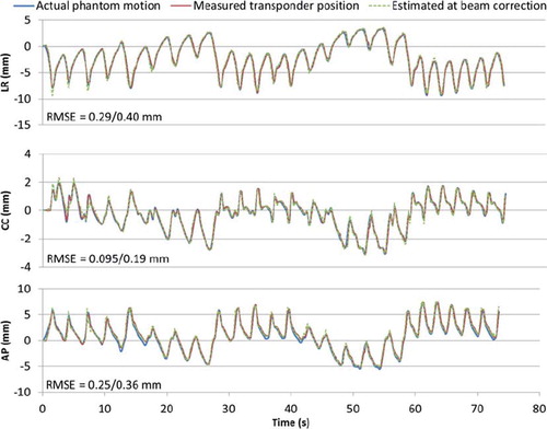
Table I. Results of experiments: mean rms of position estimation errors in mm.
Tracking accuracy using the wired EM transponder
summarizes the rms tracking errors for all the experiments. shows an example of tracking accuracy in beam's eye view of the same experiment as shown in , i.e. an arc treatment with a baseline shifted lung tumor trajectory. The target motion is generally tracked very well, although with a slightly larger displacement due to gantry sag, most notable at about 40 s after treatment start, i.e. when the gantry was at the top of the rotation arc. Larger tracking errors due to gantry sag are also seen in the results for the anterior field in . The error was small compared to the would-be error without tracking, which would be equal to the target displacement (blue line in ). Prostate tumors were tracked equally well but without latency compensation by prediction due to the non-repetitive patterns of prostate tumor motions. The mean rms of the 2D beam-target tracking error was 0.69 mm (prostate) and 0.98 mm (lung tumors) with tracking and 3.4 mm (prostate) and 5.3 mm (lung tumors) without tracking. shows 2D rms errors of all arc experiments for comparison.
Figure 4. Tracking accuracy observed in MV images in the same experiment as shown in . Trajectories are shown for the target (blue), visualized by the shadow of the tungsten sphere on the portal MV images, and for the center of the circular field shaped by the DMLC aperture (red). The green curve is the tracking error, i.e. the difference between the target and the DMLC aperture positions.
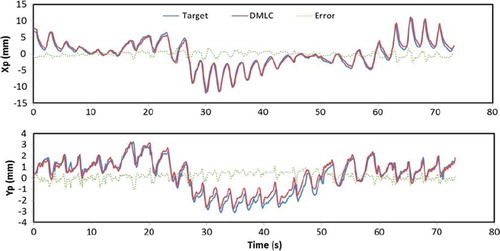
Figure 5. 2D root-mean-square errors with (black circles) and without (gray squares) tracking for arc treatments. Results were similar for static treatments (see ). The 2D rms target localization errors at time of localization and at time of beam correction are also shown. Tumor trajectory labels are explained in .
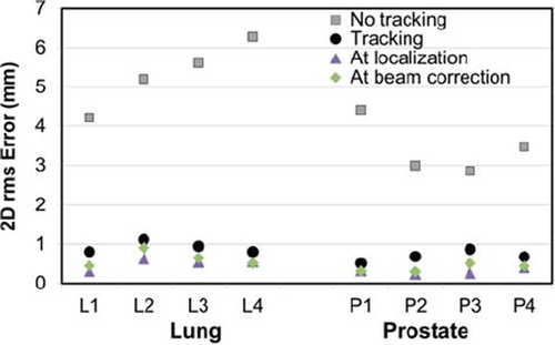
Table II. Results of experiments: rms of tracking errors in mm.
Discussion
We integrated a novel EM transponder localization system with DMLC tracking and investigated it for arc and static field delivery. We examined the latency, the positional measurement drift at no movement, the geometric position localization accuracy, and the tracking accuracy of the integrated system. This phantom study validated the use of the investigated EM localization system with tracking.
The EM transponder proved stable well below 1 mm once set up and placed correctly over the receiving part of the couch top. The integrated EM transponder showed very little drift (0.3 mm) in position measurement in the LR direction and no general drift in the CC and AP directions over a period of 60 min. The CC and AP directions were distributed about mean displacements of -0.04 mm and 0.13 mm, respectively. The AP-direction showed the highest distribution in measured displacements covering displacements from the isocenter between -0.1 mm and 0.5 mm with a rms of 0.17 mm. The AP direction was also the only direction that did not yield mean rms errors below one tenth of a mm for any trajectory (see ), which could perhaps be attributed to less stability in the AP direction. The AP direction is perpendicular to the plane of the receiver antennae which may be the reason for slightly less accuracy in this direction.
The integrated system has a tracking latency of 140 ms, which is slightly faster than the Calypso EM transponder system (150 ms latency) [Citation24] and the optical RPM system (160 ms latency) [Citation23]. While a shorter tracking latency has been reported for the gimbal based VERO system [Citation25], this is the shortest latency reported for DMLC tracking using a standard linac. The investigated localization system is shown to be accurate with a mean rms position localization error of 0.54 mm in three dimensions. Coupled with the short tracking latency, it results in sub-mm rms tracking errors for most tumor trajectories. The Calypso EM transponder system has been shown to produce sub-2 mm tracking errors for moderately varying as well as highly varying respiratory trajectories and sub-1 mm tracking errors for prostate trajectories [Citation13]. The integrated system presented here thus produces tracking errors comparable to those of Calypso. Tracking results of the integrated system studied here are also comparable to those reported in studies of image-based tracking [Citation7,Citation8,Citation12]. However, use of EM transponders for position localization during tracking is attractive since ionizing radiation is avoided.
As the trajectories were chosen due to their respective difference, motion magnitude, and complexity, it is reasonable to assume that the tracking errors presented here represent errors in the upper level, i.e. typical prostate and lung trajectories should result in tracking errors lower than the values presented here. The relatively large circular field aperture in this study allowed for accurate refitting of the field shape even to small target position shifts perpendicular to the DMLC leaves. As a result, a high tracking accuracy was obtained. For more realistic DMLC apertures, e.g. for IMRT, the leaf fitting procedure would lead to additional geometric errors due to the finite leaf width of 5 mm. shows that the short latency, as well as prediction (for lung tumor trajectories only), has contributed very little additional error to the 2D rms error at time of beam correction in comparison with the 2D rms error at time of localization. This is true for all but the high frequency trajectories of both lung and prostate tumors which represent the peak of complexity due to the rapid motion of the target. We would expect 2D rms tracking errors to be comparable to estimated positions at time of beam correction. However, some 2D rms tracking errors are substantially larger (). rms tracking errors exceeding 1 mm were seen in a few cases with very fast target motion along the leaf travel direction (, High frequency lung tumor trajectory L2, Yp direction) or perpendicular to the leaf travel direction (, Mainly LR motion lung tumor trajectory L3, Xp direction, anterior field). The generally larger rms errors for the anterior field direction were caused by gantry sag, which resulted in maximum beam-target deviations for anterior gantry angles (, Yp direction, around 40 s). Online correction for gantry sag and pre-experiment optimization of the DMLC aperture orientation to the dominant tumor motion direction could potentially decrease the maximum error markedly.
Although lung tumor trajectories were used in this study of geometric accuracy of the integrated system, clinical use of a wired transmitter as an implant marker for lung tumors is not likely. The only RayPilot study published so far [Citation17] used transponder insertion in the urethra rather than the intended trans-perineal implantation in the prostate. Further challenges for clinical implementation of the EM transponder with tracking include assurance of static in vivo interfraction transponder position with respect to the tumor and development of quality assurance programs for tracking.
Conclusion
In conclusion, DMLC tracking was integrated with a novel implantable EM transponder localization system and investigated for arc and static field delivery. The EM transponder system showed good stability during experiments. The tracking latency of 140 ms is the shortest reported so far for DMLC tracking on a standard linac. The system provides 0.5 mm geometrical errors for position measurement in three dimensions and sub-mm geometrical tracking errors for most trajectories.
Acknowledgements
We gratefully thank Patrick Kupelian and Katja Langen (M. D. Anderson Cancer Center, Orlando) for the prostate trajectories, Yelin Suh and Sonja Dieterich (Stanford University) for the lung tumor trajectories, Tomas Gustafsson (Micropos Medical AB) for technical information on the Micropos RayPilot system, and Roman Iustin and Andreas Bergqvist (Micropos Medical AB) for modifications of the RayPilot system to allow integration with the tracking program.
This work was supported by NCI Grant R01CA93626 and by research grants from Varian Medical Systems), The Danish Cancer Society, and CIRRO – The Lundbeck Foundation Center for Interventional Research in Radiation Oncology and The Danish Council for Strategic Research.
Declaration of interest: The authors report no conflicts of interest. The authors alone are responsible for the content and writing of the paper.
References
- Keall PJ, Mageras GS, Balter JM, Emery RS, Forster KM, Jiang SB, . The management of respiratory motion in radiation oncology report of AAPM Task Group 76. Med Phys 2006;33:3874.
- Gottlieb KL, Hansen CR, Hansen O, Westberg J, Brink C. Investigation of respiration induced intra- and inter-fractional tumour motion using a standard Cone Beam CT. Acta Oncol 2010;49:1192–8.
- Månsson Haskå T, Honore H, Muren LP, Høyer M, Poulsen PR. Intrafraction changes of prostate position and geometrical errors studied by continuous electronic portal imaging. Acta Oncol 2008;47:1351–7.
- van der Voort van Zyp NC, Prévost J-B, Hoogeman MS, Praag J, van der Holt B, Levendag PC, . Stereotactic radiotherapy with real-time tumor tracking for non-small cell lung cancer: Clinical outcome. Radiother Oncol 2009; 91:296–300.
- D'Souza WD, Malinowski KT, Van Liew S, D'Souza G, Asbury K, McAvoy TJ, . Investigation of motion sickness and inertial stability on a moving couch for intra-fraction motion compensation. Acta Oncol 2009;48:1198–203.
- Poulsen PR, Cho B, Sawant A, Ruan D, Keall PJ. Dynamic MLC tracking of moving targets with a single kV imager for 3D conformal and IMRT treatments. Acta Oncol 2010;49:1092–100.
- Poulsen PR, Cho B, Sawant A, Keall PJ. Implementation of a new method for dynamic multileaf collimator tracking of prostate motion in arc radiotherapy using a single kV imager. Int J Radiat Oncol Biol Phys 2010;76:914–23.
- Poulsen PR, Cho B, Ruan D, Sawant A, Keall PJ. Dynamic multileaf collimator tracking of respiratory target motion based on a single kilovoltage imager during arc radiotherapy. Int J Radiat Oncol Biol Phys 2010;77:600–7.
- Zimmerman J, Korreman S, Persson G, Cattell H, Svatos M, Sawant A, . DMLC motion tracking of moving targets for intensity modulated arc therapy treatment – a feasibility study. Acta Oncol 2009;48:245–50.
- Falk M, af Rosenschöld PM, Keall P, Cattell H, Cho BC, Poulsen P, . Real-time dynamic MLC tracking for inversely optimized arc radiotherapy. Radiother Oncol 2010;94:218–23.
- Poulsen PR, Cho B, Sawant A, Ruan D, Keall PJ. Detailed analysis of latencies in image-based dynamic MLC tracking. Med Phys 2010;37:4998.
- Cho B, Poulsen PR, Sloutsky A, Sawant A, Keall PJ. First demonstration of combined kV/MV image-guided real-time dynamic multileaf-collimator target tracking. Int J Radiat Oncol Biol Phys 2009;74:859–67.
- Sawant A, Smith RL, Venkat RB, Santanam L, Cho B, Poulsen P, . Toward submillimeter accuracy in the management of intrafraction motion: the integration of real-time internal position monitoring and multileaf collimator target tracking. Int J Radiat Oncol Biol Phys 2009;74: 575–82.
- Krauss A, Nill S, Tacke M, Oelfke U. Electromagnetic real-time tumor position monitoring and dynamic multileaf collimator tracking using a Siemens 160 MLC: Geometric and dosimetric accuracy of an integrated system. Int J Radiat Oncol Biol Phys 2011;79:579–87.
- Shah AP, Kupelian PA, Willoughby TR, Langen KM, Meeks SL. An evaluation of intrafraction motion of the prostate in the prone and supine positions using electromagnetic tracking. Radiother Oncol 2011;99:37–43.
- Cherpak A, Serban M, Seuntjens J, Cygler JE. 4D dose-position verification in radiation therapy using the RADPOS system in a deformable lung phantom. Med Phys 2011; 38:179.
- Kindblom J, Ekelund-Olvenmark A-M, Syren H, Iustin R, Braide K, Frank-Lissbrant I, . High precision transponder localization using a novel electromagnetic positioning system in patients with localized prostate cancer. Radiother Oncol 2009;90:307–11.
- Keall PJ, Sawant A, Cho B, Ruan D, Wu J, Poulsen P, . Electromagnetic-guided dynamic multileaf collimator tracking enables motion management for intensity-modulated arc therapy. Int J Radiat Oncol Biol Phys 2011;79:312–20.
- Malinowski K, Noel C, Lu W, Lechleiter K, Hubenschmidt J, Low D, . Development of the 4D Phantom for patient-specific, end-to-end radiation therapy QA. Proceedings of SPIE. San Diego, CA, USA. 2007. 65100E–65100E-9.
- Suh Y, Dieterich S, Cho B, Keall PJ. An analysis of thoracic and abdominal tumour motion for stereotactic body radiotherapy patients. Phys Med Biol 2008;53:3623–40.
- Langen KM, Willoughby TR, Meeks SL, Santhanam A, Cunningham A, Levine L, . Observations on real-time prostate gland motion using electromagnetic tracking. Int J Radiat Oncol Biol Phys 2008;71:1084–90.
- Srivastava V, Keall P, Sawant A, Suh Y. TU-C-M100J-06: Accurate prediction of intra-fraction motion using a modified linear adaptive filter. Med Phys 2007;34:2546.
- Sawant A, Venkat R, Srivastava V, Carlson D, Povzner S, Cattell H, . Management of three-dimensional intrafraction motion through real-time DMLC tracking. Med Phys 2008;35:2050–61.
- Sawant A, Cho B, Poulsen P, Ruan D, Newell J, Petersen J, . Performance analysis of an electromagnetic transponder-based DMLC tracking system for 4D radiotherapy delivery. Int J Radiat Oncol Biol Phys 2009;75(3Suppl 1):S575–6.
- Depuydt T, Verellen D, Haas O, Gevaert T, Linthout N, Duchateau M, . Geometric accuracy of a novel gimbals based radiation therapy tumor tracking system. Radiother Oncol 2011;98:365–72.