
Abstract
At particle therapy facilities with pencil beam scanning, the implementation of a ripple filter (RiFi) broadens the Bragg peak (BP), which leads to fewer energy steps from the accelerator required to obtain an homogeneous dose coverage of the planned target volume (PTV). At the Universitätsklinikum Gießen und Marburg, Germany, a new second generation RiFi has been developed with two-dimensional groove structures. In this work we evaluate this new RiFi design. Methods: The Monte Carlo (MC) code SHIELD-HIT12A is used to determine the RiFi-induced inhomogeneities in the dose distribution for various ion types, initial particle energies and distances from the RiFi to the phantom surface as well as in the depth of the phantom. The beam delivery and monitor system (BAMS) used at Marburg, the Heidelberg Ionentherapiezentrum (HIT), Universitätsklinikum Heidelberg, Germany and the GSI Helmholtzzentrum für Schwerionenforschung, Darmstadt, Germany is modeled and simulated. To evaluate the PTV dose coverage performance of the new RiFi design, the heavy ion treatment planning system TRiP98 is used for dose optimization. SHIELD-HIT12A is used to prepare the facility-specific physical dose kernels needed by TRiP, and for recalculating the physical dose distribution after TRiP optimization. Results: At short distances from the RiFi to the phantom surface fine structures in the dose distribution are observed. For various RiFis, ion types and initial particle energies the distance dmax at which maximum dose inhomogeneity occurs is found and an expression for dmax is deduced. The distance d0.01 at which the dose inhomogeneity is less than 1% is estimated and used as a threshold distance at which dose distributions are considered homogeneous. The MC data are found to agree with analytical expressions for dmax and d0.01; both are inversely related to the angular distribution. Increasing scatter from the beam delivery and monitoring system results in reduced dmax and d0.01. Furthermore, dmax and d0.01 are found to be proportional to the RiFi period λ. Conclusion: Our findings clearly indicate that the dose inhomogeneity induced by RiFis does not add uncertainties to the dose distribution in the clinical setting. The new RiFi design can be used in treatments to obtain homogeneous PTV dose coverage with fewer energy steps while improving lateral penumbra, thereby reducing the required treatment time.
Compared to the passive scattering dose delivery technique, pencil beam scanning can reduce integral dose with respect to scattered beams and make field patching techniques and IMPT possible [Citation1]. For a beam delivery system utilizing pencil beam scanning the spread-out Bragg peak (SOBP) is made by a superposition of multiple Bragg peaks (BP), each located at a specific target depth. The planning target volume (PTV) is thus divided into individually shaped energy slices of different depths. Pristine beams of mono-energetic carbon ions result in very sharp BPs, especially at low penetration depths due to the corresponding low energy straggling. This results in an unreasonably large number of energy steps required to achieve a homogeneous irradiation of the target volume and increases time for dose delivery, as each energy shift may take up to 5 seconds, whereas irradiating the energy slice typically is much faster. Merely reducing the number of energy slices results in inhomogeneities in the dose distribution in the form of dose ripples in the SOBP.
The ripple filter (RiFi) [Citation2] works as a passive energy modulator and reduces this inhomogeneity, so larger energy steps can be applied, shortening the treatment time. A RiFi is a plastic material with variable thickness in the form of periodic groove structures which widens the BP to a smooth Gaussian. The width of the broadened BP is related to the maximum RiFi thickness (the modulation strength). All RiFi-thicknesses stated in this paper are the actual physical thickness of the RiFis. To date, first generation RiFis in the form as described in [Citation2] are and have been applied for patient therapy at the GSI Helmholtzzentrum für Schwerionenforschung, Darmstadt, Germany and the Heidelberg Ionentherapiezentrum (HIT), Universitätsklinikum Heidelberg, Germany. With a similar shape they are used for patient treatment at the CNAO project [Citation3] as well as at the facility HIMAC, Inage, Japan [Citation4]. RiFis can also be applied for proton beams, even if proton BPs by nature have an increased width due to scattering and energy straggling.
One disadvantage of this first generation RiFi is its 1D groove shape which requires a base layer serving no other purpose than holding the filter together. This base layer adds unnecessary scattering (more than required for the intended blur-out effect [Citation2]) which can be avoided.
Recently, at the therapy facility Universitätsklinikum Gießen und Marburg, Germany, a new second generation RiFi has been designed. These filters are 2D in their groove shape and manufactured by the use of stereo lithography (rapid prototyping). The new design combined with the new manufacturing technique makes it possible to improve the groove shapes and increase the maximum thickness of the range modulating part of the RiFi while removing the base layer.
However, the new developments of the 2D RiFi lead to a number of questions: 1) Surface dose inhomgeneities: The placement of a RiFi in the beam path induces fine structures in the dose distribution at target surface (e.g. the skin of the patients) for small distances from the RiFi. The dose fine structures are thought to be caused by a kind of edge scattering effect due to an inhomogeneous scattering strength, which in turn is caused by the alternating thickness of the RiFi; 2) Range inhomogeneities: Second, the alternating loss of particle energy in the RiFi and corresponding alternating particle ranges in the target can result in dose inhomogeneity at the BP for very low distances from the RiFi; 3) SOBP dose inhomogeneities: Third, the question arises how broad can the energy steps be made while still keeping an adequately flat dose distribution in the SOBP; 4) Lateral and distal dose fall-off: Finally, we have investigated the effect of RiFis on the beam penumbra at the surface, inside the target and at the distal edge of SOBPs.
In this paper we shall address these concerns and establish a distance from the RiFi as a function of particle energy where the RiFi does not influence the dose distribution in a negative way, as well as an estimation for the energy step sizes yielding a homogeneous dose coverage in the SOBP.
The Monte Carlo (MC) particle transport code SHIELD-HIT12A [Citation5–8] allows for directly addressing these questions on a microscopic level, while the treatment planning system TRiP98 [Citation9,Citation10] can be used in conjunction with SHIELD-HIT12A in order to generate, recalculate and evaluate SOBPs. In addition to the MC simulation, we also present an analytical description for a simplified case in order to verify our MC findings. Since RiFis are more relevant for ions heavier than protons, the bulk of the simulations are performed with carbon-12 projectiles. Also, this ion is the most widely used heavy ion at particle therapy facilities.
Material and methods
Analytical solution of two-thickness ripple filter
The surface dose inhomogeneities can be calculated by MC simulations as well as analytically (with some limitations). Here we present an analytical evaluation of a simplified 1D RiFi with only two thicknesses and rectangular groove shapes. The two thicknesses yield an angular scattering σα,thick and σα,thin, respectively. The beam direction is the z-direction. With λ as the RiFi period, the propagation and inhomogeneous scattering of the beam after traversing the two- thickness RiFi can be expressed as:
with
where σα is the angular distribution in mrad and σα⋅z is the corresponding spatial distribution in mm. Here, the summation is done over a total number of 21 grooves, i.e. −10 ≤ i ≤ 10. The distance dmax at which maximum surface dose inhomogeneity is seen can be deduced from calculating f(x,z) numerically. The results can approximately be described as:
and the minimum distance d0.01 at which the homogeneity from Equation 1 is better than 0.5%, being 1% for a 2D-RiFi having rectangular steps in both x and y direction, can be approximated by:
The 1% threshold is chosen as a conservative estimate of dose inhomogeneity. Equation 4 stands in relation to the Supplementary material (available online at http://informahealthcare.com/doi/abs/10.3109/0284186X.2012.832834). This rectangular two-thickness RiFi would result in cruder and more pronounced dose fine structures than a real RiFi with Gaussian shaped groove structures. Therefore the expressions presented here are representing the worst case scenario. In addition, it represents the old RiFi-design with 1D groove structure. However, as shall be shown in the discussion section, this analytical model also fits the new 2D design very well.
Beam model
Using blueprints of the Marburg beam line, the beam application and monitoring system (BAMS) is modeled using SHIELD-HIT12A. The BAMS consists of the vacuum exit window, several redundant ion chambers, multiwire proportional counters and the RiFi. It is based on the originally design from GSI, and is currently also in use at Marburg and HIT [Citation11]. An initial angular distribution of 1 mrad beam divergence (ion optics) is used and the beam is focused at the isocenter 108 cm from the RiFi, 140 cm from the beginning of the BAMS. A 2 × 2 cm2 homogeneously scanned field is used, being much larger than the RiFi structure period λ of 0.15 cm. The BAMS has a scattering/straggling effect itself, and should therefore be included in the simulation. The actual beam divergence and energy spread distributions after the BAMS are not in a form for precisely setting up the MC simulation. We think it is more precise to apply the well-established and simpler beam characteristics before the BAMS and simulate the subsequent perturbations of the primary beam. Simulations without BAMS were performed in order to evaluate the importance of the BAMS in regard to the disappearance of RiFi-induced dose inhomogeneities. Also, the calculation without BAMS is more generic and a kind of worst case estimation, for users that have or intend a very thin nozzle. For such simulations, the beam is set to originate 0.1 cm before the RiFi in a vacuum environment. The focus parameter is then adjusted accordingly, so the beam is still focused at the isocenter.
The target is a small water phantom with 5 × 5 cm2 width and varying depth, depending on whether depth-dose curve are needed or not, in order to keep the calculation times short.
Simulations of RiFi-induced surface dose and range inhomogeneities
Surface dose is scored at the water phantom surface orthogonal to the beam axis. A 0.1 mm/bin resolution is used and 3 × 3 cm2 (300 × 300 bins) is scored in the x and y direction with 1 bin in the z direction (direction of the primary beam) with a bin size of 1 mm/bin. The center of the scoring volume is set at the center of the 2 × 2 cm2 field. An integration over the y-direction is performed, yielding dose as a function of 1D, which is used for data analysis (see subsection Depth inhomogeneities in the SOBP). The y-integration improves the quality of the results by reducing the statistical noise; in the last paragraph of subsection Depth inhomogeneities in the SOBP this method is validated for 2D RiFi. The surface dose inhomogeneity is found as a function of the distance from the RiFi to the phantom surface d by use of multiple MC simulations to find d0.01 and dmax. As the phantom is moved the beam is kept focused at the isocenter. The RiFi is kept stationary since it is an integrated part of the BAMS and not moveable. For some values of d, the lateral dose distribution is also recorded not only at the phantom surface, but also at various distances between the phantom surface and the RiFi. The procedures are repeated for a range of different initial particle energies and/or different particle types.
Data sets are obtained for 1D 3 mm thick RiFi as well as for 2D 3.6 and 6 mm thick RiFis. The simulated energy range of the carbon ions is between 80 and 400 MeV/u and the energy range of the protons between 50 and 230 MeV in order to reflect the energies available at the Marburg accelerator. In SHIELD-HIT12A, the RiFi can be implemented and simulated in a similar way as described by [Citation12], and its validity has been verified for the 1D case by [Citation13] against experimental data. External ICRU49 and 73 stopping power tables are used from the open-source stopping power library libdEdx [Citation14,Citation15]. SHIELD-HIT12A can generate depth dose kernels for use in TRiP, making it possible to include additional physical base data than the ones already available in the TRiP library. In this case calculated beam kernels simulating the Marburg beam line are used for TRiP. Five hundred thousand simulated particles are used for each energy step. TRiP then uses these depth-dose kernels to build the SOBPs. Resulting accelerator control files can then in turn be read by SHIELD-HIT12A to recalculate depth dose distributions in arbitrary targets, in this case a water phantom at various distances d. For these calculations 107 particles are simulated.
Oscillating fitting procedure
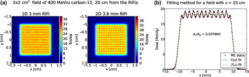
For specific distances d from the RiFi to the phantom surface, fine structures in the surface dose distribution resulting in inhomogeneities from the mean dose are observed at the phantom surface (also called “zebra-burners”). These zebra-burners are shown in for a 400 MeV/u 12C beam and one (1D) RiFi of the first generation compared to a 2D RiFi of the second generation. An oscillating fitting procedure is developed in order to quantify this dose inhomogeneity at the phantom surface as well as at the depth of the phantom. Several strategies are attempted, the most robust method is to fit a product of a non-oscillating F(x) and an oscillating (sinusoidal) function Osc(x) to the lateral dose data.
Figure 1. Simulated dose distribution at the surface of the target scored orthogonal to a 400 MeV/u 12C beam with a distance, d, of 20 cm between the RiFi and the phantom surface is shown in (a). In (b) is presented an example of the fitting method used to find the quantity ΔI/I representing the dose inhomogeneity for this particular case. See Equations 5–9.
F(x) is given as
where x is the lateral position and b, g0, g1 and gσ are the fitting parameters. Here 2b is the size of the field, gσ the steepness of the border, g1 the mean dose level of the field and g0 an offset, normally equal to 0.
In G(x) the Gaussian error function is included:
F(x) then describes the homogeneous superposition of (infinitely narrow) Gaussians, where the center of these superimposed Gaussians are in the range from −b to b. Especially the dose fall-off at the borders of the field is well described by F(x).
The function Osc(x) is given as
In the Supplementary material (available online at http://informahealthcare.com/doi/abs/10.3109/0284186X.2013.832834), it is described that a periodic superposition of shifted Gaussians with a distance larger than σ results in an oscillation at the plateau. The situation of the scattered field from the RiFi can be considered as a series of periodic superpositions of Gaussians with different contributions, different phase shifts and different values of σ but always with the same period λ (compare the example of the simplified two-thickness RiFi in subsection Analytical solution of two-thickness ripple filter). Therefore, if the dose ripple is not too high, the field can be approximated by a superposition of a series of harmonic functions with different phase shifts and amplitudes but having always the same frequency (namely the RiFi period) which results again in a harmonic dose oscillation that is received in the near-field behind the RiFi. This mathematical result is confirmed by the MC-simulations of this work.
In the end F(x) and Osc(x) is connected in the following way:
Then from F(x), the amplitude A gives the percentage difference between the oscillating and the non-oscillating case. This can be directly translated to a value for dose inhomogeneity in the form of:
with Imax being the maximum intensity or the maximum dose value for the MC data set and Imean being the mean value of the dose distribution (excluding the lateral fall-off region) or the maximum intensity of the non-oscillating function. An example of the procedure is presented in .
However, this method is only strictly correct for the 1D RiFi case. For 2D groove structures this method underestimates the overall dose inhomogeneity by a factor of 2. The reason is that for a 2D RiFi we should assume a 2D oscillating fitting function Osc(x,y) = (1 − B cos(x))⋅(1 − B cos(y)). Then, neglecting the B⋅B term, one obtains a minimum and maximum value of 1–2B and 1 + 2B, respectively. This means the size of the ripple is 2B. Using one single bin in the y (or) x direction, corresponds to an integration over all data point in that direction, i.e. f(x) = ∫F(x,y) dy = C(1 − B cos(x)), and one obtains a ripple of only B in size, instead of 2B.
Therefore, as long as the RiFi is symmetric (t(x,y) = t(y,x) with t being the RiFi thickness), one can easily apply the 1D oscillation function Osc(x) and subsequently scale ΔI/I values with a factor of 2 for the 2D RiFis. For the results shown in this paper, this integration and scaling method was used. A fit in 2D is not performed, since when using the integration method (one bin in either the x or y direction) the statistics becomes better.
Spread-out Bragg peak dose inhomogeneities and penumbra
In a cubic water phantom with the lateral side length of 10 cm × 10 cm and various thicknesses, a cubic PTV with the dimensions 5 × 5× 5 cm3 is located at the isocenter. This PTV is large enough to require at least eight energy steps when using the 6 mm thick RiFi and more for the thinner RiFis. The PTV is located at three different phantom depths, starting at 40, 150 and 260 mm respectively, and the phantom thickness is scaled accordingly. The prescribed dose to the PTV is set to 3 Gy physical dose. The TRiP optimized SOBPs are evaluated using the visualization tool PyTRiP [Citation16,Citation17].
For 12C ions, three 2D RiFis are investigated with thicknesses of 3.6, 4 and 6 mm. For each RiFi, three energy step sizes (in mm) are investigated, one of them matching the respective RiFis modulation thickness. For protons the main focus is on the thickest RiFi of 6 mm.
The quality of the SOBPs is evaluated by estimating the deviation from the mean dose due to dose ripples in depth of the PTV. The SOBP ripples have non-periodic behavior, which is why the sinusoidal fit method described earlier cannot be used in this case. Instead for each SOBP the mean dose Imean is found and in each ripple the largest deviation from the mean dose is found. The average deviation is found for all ripples in the SOBP, and the ripple with the highest deviation (typically found at the proximal or distal edge of the SOBP) is recorded. Uncertainties are here estimated to be below 10% of the estimated average deviation from mean dose.
Lateral fall-off is found using standard convention, i.e. the distance from the 80–20% dose level. Lateral fall-off is investigated at the phantom surface and at various depth inside the water phantom. Distal fall-off is determined as well, however, due to the presence of the carbon ion fragmentation tail, the 20% dose level may be located in the fragmentation tail. Therefore the distance between the 90–40% dose levels are applied instead. The same definition for distal fall-off is applied for protons as well for consistency, even if proton beams do not have a fragmentation tail.
Results
Surface inhomogeneities
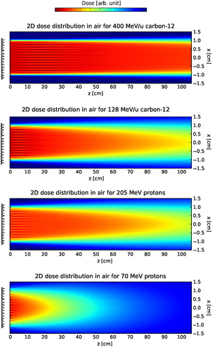
Surface dose inhomogeneities expressed by the characteristic distances dmax and d0.01fit the analytical estimation described earlier. As described earlier, for specific distances d from the RiFi to the phantom surface inhomogeneities from the mean dose are observed at the phantom surface, resulting in zebra-burners. The surface dose fine structures disappears with distance d from the RiFi, as illustrated in for 128 and 400 MeV/u carbon-12 as well as for 70 and 205 MeV protons.
Figure 2. Simulated dose distributions in air between the RiFi and the phantom surface for protons and carbon-12 ion at high and low energies. The fields are 2 × 2 cm2 (used throughout this work.
For all ΔI/I(d) curves shown in one can observe a maximum value of dose inhomogeneity at a certain distance dmax with a decrease to d0.01. shows the dose inhomogeneity as a function of d for simulations with no BAMS and without beam divergence, for simulations without BAMS and with 1 mrad beam divergence and lastly for simulations with BAMS as well as 1 mrad beam divergence. In is shown the dose inhomogeneity at phantom surface as a function of d for two second generation RiFis of 3.6 and 6 mm thickness for various energies of 12C and protons, respectively. The dose inhomogeneity ΔI/I is larger for thicker filters, since more material means a higher amount of scattering. For both carbon ions and protons it can be seen that for all RiFis independent of the thicknesses, dmax is the same value within 5%, which is higher than the noise of the simulations. This was found to be a general tendency. When the BAMS and beam divergence are not included in the simulations however, a difference in dmax of at least 20% is found for the 3.6 mm RiFi compared to the 6 mm RiFi.
Figure 3. Three plots showing dose inhomogeneity, ΔI/I, as a function of the distance, d, between 2D RiFis and the phantom surface. ΔI/I is shown for (a) different configurations as well as for different particle energies with (b) 12C and (c) protons.
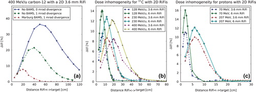
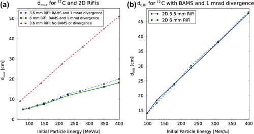
That a value dmax exists fits the analytical expressions (subsection Analytical solution of two- thickness ripple filter). show how dmax is larger for higher initial particle energies, that the dose inhomogeneity is higher for the thicker RiFi and that dmax is lower for protons than for carbon ions. For the same range in water, dmax differs by a factor of approximately 3.5 between proton and carbon ions, as seen by comparing . This corresponds roughly to the difference in the effect of small-angle multiple scattering between protons and carbon ions [Citation18]. It is also found from simulations that dmax is proportional to the particle energy and inverse proportional to the Z/A-fraction of the ions. The found values of dmax and d0.01 are shown for 2D RiFis in , respectively. Linear dependencies of the energy can clearly be seen. In addition, in once more the importance of BAMS and beam divergence in regard to the disappearance of the RiFi-induced dose inhomogeneity is illustrated.
Figure 4. In (a) is shown dmax as a function of particle energy with and without BAMS and beam divergence for 2D 3.6 mm RiFi and with BAMS for 2D 6 mm RiFi. In (b) d0.01 for different 2D RiFi thicknesses is shown.
Range inhomogeneities
Range inhomogeneities in the phantom are only observed for carbon ions at energies below 200 MeV/u and values of d ≤ 15 cm, see also , which illustrates this effect. For protons, no dose inhomogeneity is observed in the depth of the phantom at any distance or energy.
Figure 5. Dose distribution in the water phantom for different RiFi<−> phantom surface distance d for 128 MeV/u carbon-12. The dimensions of the figures are not to scale: One is the typical situation at the isocenter, the other is the extreme (unrealistic) situation where a range inhomogeneity can appear at all.
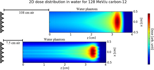
Range inhomogeneity is seen to be higher for a smaller value of d. Values of ΔI/I higher than 40% are seen at the BP distal edge for d < 5 cm for the 6 mm RiFi.
When d< dmax, then the maximum inhomogeneity is found inside the water phantom. This leads to two local maxima of dose inhomogeneity within the water phantom; the first maximum for the fluence (surface) buildup and the other maximum stemming from the range inhomogeneity.
Depth inhomogeneities in the SOBP
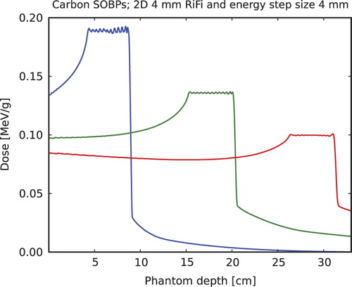
SOBP ripples are evaluated for PTV ranges 50–90, 150–200 and 260–310 mm and for 3.6, 4 and 6 mm 2D RiFis and energy step sizes centered around the modulating strength or thickness of the respective RiFi (in mm). In carbon ion SOBPs with various penetration depths are shown, here only for the 4 mm RiFi with 4 mm energy step sizes. It is found in general that best homogeneity is achieved when the RiFi thickness matches the energy step size. Then, at high penetration depths (> 150 mm), the average inhomogeneity is found to be less than 0.5%, and is below 1% for smaller penetration depths. Maximum ripple deviation for the largest ripple in the SOBP is always below 2% for the 2D RiFi.
Figure 6. SOBPs simulated for 12C and a 50 mm long PTV in depth of a water phantom starting at 40, 150 and 260 mm, respectively, for a 4 mm thick 2D RiFi and energy step sizes equal to this thickness.
The lateral and distal fall-offs are investigated as well, and for carbon ions and protons, the increase in distal fall-off after the SOBP when the thinnest (3 mm) RiFi is used compared to the thickest (6 mm) RiFi is found to be no more than 0.6 to 0.8 mm, depending on penetration depth. In the case of carbon ions, of the lateral fall-off, the relative increase occurring when using a RiFi compared to not using one is found to be about 6–8% for the 3.6 mm and 9–13% for the 6 mm RiFi depending on particle energy.
Discussion
The dose inhomogeneity caused by the introduction of a RiFi disappears with the distance from the RiFi. This is thought to be caused by the combination of two effects: 1) The enlargement by the distance of the edge scattering effect of a single rill; and 2) The “smear-out” of the inhomogeneity by the superposition of many rills. A larger beam width prior to the RiFi due to the BAMS and beam divergence results in a faster “smear-out”.
It is found that both surface and range inhomogeneities in general depends on the initial angular distribution of the beam before hitting the RiFi. This angular distribution is caused by multiple small-angle scattering in the BAMS as well as by the divergence of the beam from the ion optics. A higher effect of scattering means that the dose inhomogeneity is smeared out earlier. As a result the patients can be treated closer to the exit window, but a downside is that a higher amount of scattering also means a higher lateral and distal widening of the beam. In any case, if the patient is positioned at d≥ d0.01, dose ripples in the patient as well as on the skin of the patient are avoided.
The analytical expressions estimating dmax and d0.01 for a two-thickness rectangular step RiFi are found to be close to the MC data obtained in this work. In particular, it is found for the 2D 3.6 mm and 6 mm thick RiFis by the MC analysis that
which is very close to the analytic solution in Equation 3. The small difference in the constant makes sense in the regard that the two-thickness RiFi results in more pronounced structures and is thought to be more aggressive concerning large range inhomogeneities. σα,thick and σα,thin are found by evaluating the angular distributions of the ions immediately behind the thickest and thinnest part respectively, using SHIELD-HIT12A. Only at very low energies of 80 MeV/u, a difference between the MC calculated dmax and Equation 11 of approximately 7% is observed, else they are in good agreement (below 1%). We anticipate that the analytical expression is not entirely valid at very low energies where the amount of multiple scattering is very high. Furthermore, from further MC data (not shown in this paper) it can be postulated that:
which fits the Highland's approximation for multiple scattering [Citation19].
The threshold distance d0.01 agrees with the analytical expression better than a few percent. A fit to the MC acquired data exactly reproduced Equation 4. For instance, at the highest initial proton energy investigated of 230 MeV, d0.01 is 17 cm. This means that in a treatment situation, the patient can be moved as close as 17 cm from the beam exit window, which reduces the generally larger lateral fall-off for pencil beam scanned proton beams. Despite of the fact that because of the ion optics the beam is slightly better focused at the original isocenter, shifting the patient is still favorable because compared to multiple scattering, the ion optics does not play a relevant role for protons. Similarly, d0.01 is found to be 48 cm for 400 MeV/u carbon-12. dmax as well as d0.01 is proportional to the RiFi period λ. A period of 0.15 cm was originally chosen at Marburg as the best solution for the design: λ should not be larger, since then the appearance of lateral dose ripples for low divergent beams could become critical.
For carbon-12 SOBPs it is found in general that energy step sizes equal to the thickness of the respective RiFi should be used. It is the experience of the authors that a RiFi with material of ϱ 1.2 g/cm3 of x mm (with an optimized 2D design) enables x mm range steps (or lower). This is proven even for the classic rill design for 2 and 3 mm (by GSI [Citation2]) and for 4 and 6 mm by the simulations presented in this paper. For protons however, larger energy step sizes can be used while still obtaining an homogeneous dose coverage in the PTV.
For a number of SOBPs, even when the SOBPs in general are smooth and without dose ripples, one or two large singular dose ripples are normally observed at the beginning and/or end of the SOBP. These dose ripples are found to cause a deviation from the mean dose of about 1% and are present in all proton SOBPs at PTV depths of 150 mm and larger. These singular dose ripples are found to be independent of the type of RiFi used and are ascribed to the dose optimization process of the treatment planning system.
The increase in distal fall-off when changing from a 3.6 mm to a 6 mm RiFi is equal for both carbon ions and protons, which is attributed to the high scan spot weight at the end of the proton PTVs, which minimizes the distal fall-off. The increase in lateral fall-off for a first generation RiFi compared to the new second generation RiFi is estimated to be larger for the same energy modulation strength. Therefore one can conclude that moving to the 2D shape, removing the non- modulating base layer of material as well as making the groove shapes sharper and finer, is an improvement of the 1D standard design in regard of beam quality.
In summary the 2D RiFi can help to reduce dose inhomogeneities, allowing the number of energy steps required to build the SOBP to be reduced. For the treatment time, currently a 5 cm thick tumor would require approximately 17 energy shifts which each may take 5 seconds or more to realize, i.e. almost 2 minutes in total including 2 seconds of irradiation time per energy slice. A 6 mm 2D RiFi could potentially reduce this to eight energy steps, allowing treatment times of under 1 minute. Shorter times enable rescanning or respiration gating within an acceptable treatment time. It also improves monitoring of the beam current and position since the particle fluence per energy step increases, improving the signal to noise ratio.
Conclusions
The inclusion of the new 2D RiFi decreases the number of energy steps needed to obtain a homogeneous irradiation of the PTV. For insufficient distances from the RiFi to the phantom surface d, fine structures with the same period as the applied RiFi can be seen in the dose distribution. This effect is thought to be due to multiple scattering effects in the alternating thickness of the RiFi.
The dose inhomogeneity caused by the fine structures increases as a function of RiFi to phantom surface distance d. A maximum is reached at dmax after which the surface dose inhomogeneity decreases until it reaches the clinical acceptable value of 1% at d0.01. dmax is found to be linearly dependent on the initial particle energy and the fraction Z/A of the ions. We have found analytical expressions for dmax and d0.01 which are in agreement with MC simulations of RiFis. dmax as well as d0.01 is proportional to the RiFi period λ, which should be no larger than 1.5 mm. For the GSI beam delivery setup modeled in this work it is found that none of the investigated RiFis influence the dose distribution in a negative way at the isocenter distance. Range inhomogeneities are found for carbon ions below 200 MeV/u which correspond to a range of 9 cm in water. However, it is concluded that the dose inhomogeneity at surface phantom is much more critical than the inhomogeneity in phantom depth. If one avoids the former, the latter is not seen. Spread-out Bragg peaks simulated with RiFis in this work have a satisfactory homogeneous PTV dose coverage as long as the RiFi thickness in water-equivalent path length times 1.2 matches the energy step size. The lateral fall-off for the new second generation RiFi compared to the first generation RiFi is estimated to be smaller for the same energy modulation strength, proving the advantages of the new design.
Thus, future beam facilities featuring active beam delivery methods such as MedAustron [Citation20] and the non-clinical Bio-LEIR facility [Citation21] may benefit from this new RiFi design.
Supplementary material
Download PDF (2.3 MB)Acknowledgments
The authors acknowledge support from the COST Action MP1002 “Nanoscale Insights into Ion Beam Cancer Therapy”. We acknowledge support from ULICE network under the EU framework, contract no. 228436.
Declaration of interest: The authors report no conflicts of interest. The authors alone are responsible for the content and writing of the paper.
References
- Schippers JM, Lomax AJ. Emerging technologies in proton therapy. Acta Oncol 2011;50:838–50.
- Weber U, Kraft G. Design and construction of a ripple filter for a smoothed depth dose distribution in conformal particle therapy. Phys Med Biol 1999;44:2765–75.
- Bourhaleb F, Attili A, Cirio R, Cirrone P, Marchetto F, Donetti M, et al. Monte Carlo simulations of ripple filters designed for proton and carbon ion beams in hadrontherapy with active scanning technique. J Phys Conf Ser 2008;02.
- Furukawa T, Inaniwa T, Sato S, Shirai T, Takei Y, Takeshita E, et al. Performance of the NIRS fast scanning system for heavy-ion radiotherapy. Med Phys 2010;37: 5672–82.
- Bassler N, Hansen DC, Lühr A, Sobolevsky N. SHIELD-HIT12A; 2012. [Internet]. [cited 2013 Aug 16] . Available from: http://www.shieldhit.org
- Hansen DC, Lühr A, Sobolevsky N, Bassler N. Optimizing SHIELD-HIT for carbon ion treatment. Phys Med Biol 2012;57:2393–409.
- Hansen DC, Lühr A, Herrmann R, Sobolevsky N, Bassler N. Recent improvements in the SHIELD-HIT code. Int J Radiat Biol 2012;88:195–9.
- Lühr A, Hansen DC, Sobolevsky N, Palmans H, Rossomme S, Bassler N. Fluence correction factors and stopping power ratios for clinical ion beams. Acta Oncol 2011; 50:797–805.
- Krämer M, Jäkel O, Haberer T, Kraft G, Schardt D, Weber U. Treatment planning for heavy-ion radiotherapy: Physical beam model and dose optimization. Phys Med Biol 2000;45:3299–317.
- Krämer M, Scholz M. Treatment planning for heavy-ion radiotherapy: Calculation and optimization of biologically effective dose. Phys Med Biol 2000;45:3319–30.
- Kraft G, Weber U. Tumor therapy with ion beams. In: Grupen C, Buvat I, editors. Handbook of particle detection and imaging. vol. 1. Heidleberg: Springer; 2011. p 1179.
- Bassler N, Kantemiris I, Engelke J, Holzscheiter M, Petersen JB. Comparison of optimized single and multifield irradiation plans of antiproton, proton and carbon ion beams. Radiother Oncol 2010;95:87–93.
- Herrmann R, Jäkel O, Palmans H, Sharpe P, Bassler N. Dose response of alanine detectors irradiated with carbon ion beams. Med Phys 2011;38:1859–66.
- Toftegaard J, Lühr A, Bassler N. libdEdx; 2010. [Internet]. [cited 2013 Aug 16] . Available from: http://libdedx.sf.net
- Lühr A, Toftegaard J, Kantemiris I, Hansen DC, Bassler N. Stopping power for particle therapy: The generic library libdEdx and clinically relevant stopping-power ratios for light ions. Int J Radiat Biol 2012;88:209–12.
- Bassler N, Toftegaard J. PyTRiP; 2013. [Internet]. [2013 Aug 2013] . Available from: https://svn.nfit.au.dk/trac/pytrip
- Bassler N, Jäkel O, Søndergaard CS, Petersen JB. Dose- and LET-painting with particle therapy. Acta Oncol 2010;49: 1170–6.
- Weber U, Kraft G. Comparisions of carbon ions vs protons. Cancer J 2009;15:325–32.
- Highland VL. Some practical remarks on multiple scattering. Nucl Instrum Methods 1975;129:497–9.
- Griesmayer E, Auberger T. The status of MedAustron. Radiother Oncol 2004;73:S202–5.
- Holzscheiter MH, Bassler N, Dosanjh M, Sørensen BS, Overgaard J. A community call for a dedicated radiobiological research facility to support particle beam cancer therapy. Radiother Oncol 2012;105:1–3.