
ABSTRACT
Background. Adaptive intensity-modulated photon and proton radiotherapy (IMRT and IMPT) of head and neck (H&N) cancer requires frequent three-dimensional (3D) dose calculation. We compared two approaches for dose recalculation on the basis of intensity-corrected cone-beam (CB) x-ray computed tomography (CT) images.
Material and methods. For nine H&N tumor patients, virtual CTs (vCT) were generated by deformable image registration of the planning CT (pCT) to the CBCT. The second intensity correction approach used population-based lookup tables for scaling CBCT intensities to the pCT HU range (CBCTLUT). IMRT and IMPT plans were generated with a commercial treatment planning system. Dose recalculations on vCT and CBCTLUT were analyzed using a (3%, 3 mm) gamma-index analysis and comparison of normal tissue and tumor dose/volume parameters. A replanning CT (rpCT) acquired within three days of the CBCT served as reference. Single field uniform dose (SFUD) proton plans were created and recalculated on vCT and CBCTLUT for proton range comparison.
Results. Dose/volume parameters showed minor differences between rpCT, vCT and CBCTLUT in IMRT, but clinically relevant deviations between CBCTLUT and rpCT in the spinal cord for IMPT. Gamma-index pass-rates were found increased for vCT with respect to CBCTLUT in IMPT (by up to 21 percentage points) and IMRT (by up to 9 percentage points) for most cases. The SFUD-based proton range assessment showed improved agreement of vCT and rpCT, with 88–99% of the depth dose profiles in beam's eye view agreeing within 3 mm. For CBCTLUT, only 80–94% of the profiles fulfilled this criterion.
Conclusion. vCT and CBCTLUT are suitable options for dose recalculation in adaptive IMRT. In the scope of IMPT, the vCT approach is preferable.
During the course of fractionated radiotherapy of head and neck (H&N) cancer, considerable anatomical changes may occur [Citation1] and substantially compromise treatment quality. An adaptation of the planned treatment might, therefore, be necessary [Citation2]. For deciding if and how to adapt, a three-dimensional (3D) dose calculation on the anatomy at the time of adaptation is required.
In photon intensity-modulated radiation therapy (IMRT), the widespread use of repeated cone-beam x-ray computed tomography (CBCT) imaging [Citation3] for patient positioning yields data sets which can also be used to evaluate the daily 3D IMRT dose distribution [Citation4]. This was investigated by several groups using varying degrees of refinement in the conversion of CBCT numbers to electron density [Citation5–13]. Approaches range from using calibration curves (phantom or patient data based) to the application of deformable image registration (DIR). Recently, also intensity-modulated proton therapy (IMPT) has been applied to the treatment of H&N lesions [Citation14,Citation15]. First comparisons of IMPT and IMRT in adaptive treatment scenarios have been published [Citation16,Citation17] and IMPT clinics are beginning to adopt IMRT-inspired CBCT-based image guidance. This opens the door to IMRT-like strategies for treatment adaptation on the basis of dose recalculations. CBCT intensity correction by deforming the planning CT to the CBCT has been shown to enable IMPT dose recalculation to an acceptable level of accuracy on the basis of clinical CBCT images [Citation18]. However, DIR-based methods are relatively complicated and require careful evaluation. To the best of our knowledge there is no evidence in the literature that a simpler intensity correction method is inadequate for IMPT dose recalculation of H&N cases.
This work aims at comparing the DIR-based intensity correction approach to a simpler CBCT to CT intensity rescaling method with population-based calibration curves for dose recalculation in IMPT and IMRT for H&N cancer. For both, IMPT and IMRT, recalculated dose distributions on intensity-corrected CBCT images and a reference replanning CT acquired close in time were compared using dose/volume parameters and gamma-index evaluation. For IMPT, where the concept of range is critical, single field uniform dose (SFUD) distributions were also compared in terms of proton range.
Material and methods
Clinical data
Dose and imaging data from nine patients previously treated with IMRT for H&N cancer, of which six patients had caudally (PCA1–6) and three cranially (PCR1–3) located tumors, were used in this study. For each subject, a planning CT (pCT), a replanning CT (rpCT), and a CBCT was available. The pCT and rpCT included all relevant tumor and normal tissue structures that had been manually delineated by the same physician (high and low dose clinical and planning target volumes (CTV, PTV), parotids, brain stem, spinal cord, chiasm, optical nerves, eyes and eye lenses). CBCT and rpCT were acquired at most three days apart (population median: one day), with the rpCT being taken between 33 and 51 days after the pCT. Details on the patient cases can be found in Supplementary Table I (available online at http://informahealthcare.com/doi/abs/10.3109/0284186X.2015.1061206), including also the target dose prescriptions. pCT and rpCT images (acquired with a Toshiba Aquilion LB scanner) were reconstructed on a 1.074 mm × 1.074 mm × 3 mm grid, CBCT images (acquired with the on-board Elekta Synergy Linac imager equipped with XVI R4.5) on a 1 mm × 1 mm × 1 mm grid.
CBCT intensity correction
The first CBCT intensity correction approach is based on DIR of the pCT to the CBCT, yielding a so-called virtual CT (vCT). A Morphons algorithm [Citation19,Citation20] has been used following the approach described and validated in [Citation18,Citation21] with only slight modifications: the initial alignment of the CBCT and pCT not only included a translational registration but also allowed for rotations, mimicking patient positioning with a modern 6-degrees-of-freedom table. This rigid registration was performed on a region of interest (ROI) containing the spine from the first to the sixth vertebrae for PatCA1–6 and the skull for PatCR1–3. Regions outside the CBCT field-of-view (FOV) were stitched with the corresponding pCT data in order to simulate a clinical adaptation scenario where a rpCT is not available.
The second intensity correction approach uses a population-based CBCT intensity rescaling. The CBCT image was aligned to the pCT applying the same rigid registration as during the vCT generation. Regions outside the CBCT FOV were again stitched with the pCT data. CT numbers were sampled at various points from both, the original pCT and the aligned CBCT, in the air outside the patient, the air inside the airways, fatty tissue, muscle, brain tissue (only PatCR1–3), soft and hard bone. These data were used to generate a CBCT to pCT Hounsfield number lookup table (HLUT) that was applied for CBCT intensity correction, yielding a so-called CBCTLUT. Due to varying CBCT intensities within the FOV, it was found necessary to establish separate HLUTs for patients with caudally and cranially located lesions by sampling HLUT points in muscle, fat and bony structures either in the neck (PatCA1–6) or the skull-base region (PatCR1–3). The applied HLUTs are shown in Supplementary Figure 1 (available online at http://informahealthcare.com/doi/abs/10.3109/0284186X.2015.1061206).
Registration: rpCT
To enable dose recalculation on the rpCT images, considered as reference in our study, they were aligned to the corresponding pCT by a rigid registration including translation and rotation, focusing on similar ROIs as used in the pCT to CBCT registration. Manual tuning of the final rigid registrations yielded corrections smaller than 1 mm.
Treatment planning and data evaluation
A research version of a commercial treatment planning system (TPS) (RayStation 4.6, RaySearch Laboratories, Stockholm, Sweden) was used to generate IMRT and IMPT plans for each patient on the basis of the pCT. The original clinical IMRT plans were used as templates and we aimed at reproducing equivalent dose distributions in terms of dose/volume parameters. The organ at risk (OAR) dose/volume constraints used for treatment planning are summarized in Supplementary Table II (available online at http://informahealthcare.com/doi/abs/10.3109/0284186X.2015.1061206). The clinical IMRT plans consisted of a simultaneous integrated boost (SIB) with two dose levels (see Supplementary Table I available online at http://informahealthcare.com/doi/abs/10.3109/0284186X.2015.1061206) in 25–32 fractions, followed by a sequential boost with five 2 Gy fractions. The boost phase was not considered in this work. Between nine (for caudal H&N lesions) and 11 (for cranial lesions) beam angles have been used in IMRT. The IMPT plans used a four-field arrangement for the caudal cases (45°, 90°, 270° and 315°; 90° and 270° blocked in shoulder area), and a three-field arrangement for the cranial cases (0°, 100° and 260°; 0° blocked in nasal/buccal cavity). A constant proton RBE (relative biological effectiveness) of 1.1 was considered throughout the study and results will be given in terms of RBE-weighted dose. For probing the proton range, SFUD plans have additionally been generated on the rpCT using a single gantry angle (see Supplementary Table I available online at http://informahealthcare.com/doi/abs/10.3109/0284186X.2015.1061206) and aiming at covering the high dose PTV. By using the rpCT for SFUD optimization, dose distributions with sharp gradients on the considered CT images could be obtained. For the SFUD plans, a dose grid with 1 mm instead of 3 mm axial spacing was employed to yield higher resolution range probing.
For dosimetric comparison of the CBCT intensity correction approaches, IMRT and IMPT plans were recalculated on the rpCT, vCT and CBCTLUT images using built-in TPS functionalities. The contours from the rpCT were copied to the aligned vCT and CBCTLUT images for dose/volume parameter evaluation. Due to the low elapsed time between rpCT and CBCT acquisitions, no contour correction was required except for the patient outline, which was updated on the vCT and copied to the CBCTLUT due to differences in the shoulder region by stitching the pCT. We recorded high and low dose PTV D95 and V95, spinal cord and brain stem D2, as well as parotid Dmean for all recalculated dose distributions. For PatCR1-3, the optical nerve, chiasm and eye D2, as well as the eye lens Dmean were additionally considered. The vCT and CBCTLUT dose distributions were also compared to the reference rpCT dose distribution by means of a 3D global gamma-index analysis using (3%, 3 mm) criteria and considering voxels with a single fraction dose above 1 Gy.
For proton range evaluation, the rpCT-based SFUD plans have been recalculated on the vCT as well as the CBCTLUT and the proton ranges, defined as distances from the patient surface to the 80% dose fall-off in beam's eye view (BEV), have been compared to that of the rpCT dose distribution.
Results
Registration
Compared to the reference rpCT, a good agreement of bony structures, internal air cavities and outer contour was observed for the vCT and the CBCTLUT. Differences between the two intensity correction methods arise close to the skull base and, in particular, between the shoulders of the patients. Here, the CBCT image is affected by severe artifacts and shadowing (see Supplementary Figure 2, available online at http://informahealthcare.com/doi/abs/10.3109/0284186X.2015.1061206). This cannot be recovered by the applied CT number rescaling, which was found to be only accurate in the spatially restricted region where the population-based CT to CBCT HLUT has been retrieved.
Dose distribution comparison
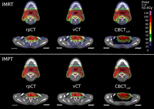
The dose distributions from IMRT and IMPT were found comparable on rpCT, vCT and CBCTLUT in regions where the CBCT is less affected by artifacts and the used HLUT-based rescaling accurate (see , top rows). In the region between the shoulders, however, the formation of hotspots in the IMRT recalculation and a severe distortion of the IMPT dose pattern are observed (see , bottom rows). The proton ranges are not correctly preserved, resulting in a considerably increased dose to the spinal cord for patients with an anteriorly positioned PTV (see Supplementary Figure 3, available online at http://informahealthcare.com/doi/abs/10.3109/0284186X.2015.1061206).
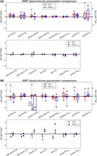
The dose/volume parameters of the recalculated 3D IMRT dose distributions were found close to the rpCT values for vCT and CBCTLUT, as illustrated in . Most parameters were found to agree within 1 Gy (considering the total dose of the SIB treatment phase), indicating no clinically relevant differences between the two intensity correction approaches in this respect. In IMPT, larger differences of the dose/volume parameters with respect to the rpCT were found for both intensity correction techniques (see ). Typically, deviations are below 4 Gy and similar for vCT and CBCTLUT, except for the spinal cord where differences up to 20 Gy emerge for the CBCTLUT.
In terms of the gamma-index analysis, slightly enhanced pass-rates for the vCT with respect to the CBCTLUT were observed for the caudal H&N cases (91–97% against 85–93%) in IMRT (). For the cranial cases, an equal performance was found. In IMPT, gamma-index pass-rates were overall smaller with respect to IMRT, particularly for the caudal H&N cases due to more pronounced deviations in the patients shoulder region (cf. Supplementary Figure 4, available online at http://informahealthcare.com/doi/abs/10.3109/0284186X.2015.1061206). Differences between vCT and CBCTLUT pass-rates (76–95% against 74–88%) were larger than in IMRT. For the cranial cases, however, comparable performances of both intensity correction strategies were identified and pass-rates similar to IMRT obtained.
Table I. Gamma-index and proton range pass-rates for vCT and CBCTLUT dose recalculations.
Proton range comparison
The amount of 1D profiles exhibiting a range deviation of less than 3 mm with respect to the rpCT was found increased for the vCT (89–95%) with respect to the CBCTLUT recalculations (80–94%, see ). Differences between both approaches were mainly located close to the skull base and in the shoulder region, were the CBCT intensities are typically reduced due to artifacts. For patients where the high dose PTV was located in regions with reduced artifacts in the CBCT and comparably stable CT numbers (PatCA2–4, see Supplementary Table IV, available online at http://informahealthcare.com/doi/abs/10.3109/0284186X.2015.1061206), only minor differences between vCT and CBCTLUT were identified.
Discussion
In this work, a DIR-based CBCT intensity correction approach (vCT) has been compared to a population-based calibration approach (CBCTLUT) in the context of dose recalculation for adaptive IMRT and IMPT for the first time. The results indicate a comparable performance of both intensity correction techniques in the scope of IMRT. However, although differences in the investigated dose/volume parameters with respect to the rpCT were mostly below 1 Gy, the gamma-index analysis, being more sensitive to local dose changes, pointed out slight inaccuracies in the CBCTLUT recalculation in the shoulder region. Here, the severe shadowing in the CBCT is not recovered by the applied intensity rescaling and the DIR-based approach yields improved agreement to the rpCT dose distribution as it adapts the pCT with its correct CT numbers to the CBCT anatomy. For the cranial cases, the PTV does not extend to this area and very similar gamma-index pass-rates for CBCTLUT and vCT were found.
Due to the steeper dose gradients, the finite particle range and the reduced number of applied beams, differences between vCT and CBCTLUT, and between these two approaches and the reference rpCT are larger in IMPT. While vCT and CBCTLUT provide comparable results for the cranial H&N cases, a notable benefit by using the vCT was found for the caudal H&N cases. In the dose/volume parameter analysis, this was particularly indicated by an improved agreement of the vCT and rpCT spinal cord D2 which could be overestimated to a clinically unacceptable level of up to 20 Gy in the CBCTLUT recalculation. Moreover, the vCT shows enhanced gamma-index pass-rates and improved range agreement, as assessed by the recalculated SFUD proton dose distributions. Even for the cranially located lesions, where very similar gamma-index pass-rates for vCT and CBCTLUT were found, an improved range agreement to the reference was identified for the vCT. The results suggest decreased differences between the investigated CBCT correction approaches for multiple field proton plans, where range deviations are less critical due to overlapping beams from different angles. It should also be mentioned that no correlation between the time elapsed between CBCT and rpCT imaging and the gamma-index pass-rate was found. This is probably due to the fact that anatomical deviations are mainly attributed to positioning uncertainties rather than internal anatomical changes which typically evolve on longer time-scales.
The identified shortcomings of the CBCTLUT approach are strongly related to intrinsic CBCT artifacts, in particular shadowing effects that cannot be corrected for by the HLUT-based intensity rescaling. Dose recalculation accuracy also suffers from variation of CT numbers within the FOV, such that the CBCTLUT can only be accurate in a restricted part of the FOV, often being smaller than the extended target volumes of H&N cancer patients. Separate HLUT scaling tables for different locations of the high dose PTVs are thus deemed necessary. Eventually, major improvements of CBCT intensity rescaling approaches can only be expected from more advanced CBCT instrumentation (e.g. with larger FOV), improved reconstruction techniques with reduced artifacts and more accurate image intensities [Citation22,Citation23] or potentially by application of compressed sensing approaches. Although the CBCTLUT approach is computationally inexpensive, it has to be noted that initial generation of the used HLUT table is a time consuming manual procedure. In future, this procedure could, however, be automated by applying techniques like scale-invariant feature transform [Citation24] to identify matching points in the CBCT and pCT and retrieve the corresponding CT numbers for input to the HLUT. DIR-based CBCT correction approaches, on the other hand, require thorough initial quality control of the applied registration algorithm and of the obtained deformation fields.
Beyond the previously discussed advantages, the DIR approach enables automatic generation of up-to-date structures on the generated vCT by warping the contours delineated on the pCT to the recent patient anatomy of the CBCT [Citation18]. This is a substantial advantage over the CBCT intensity rescaling approach since segmentation on the low-contrast, artifact-prone CBCT images is a challenging, highly time consuming task and since an up-to-date delineation is an indispensable prerequisite for adaptive radiotherapy.
In summary, we have carefully compared DIR- and lookup table-based CBCT intensity correction techniques for IMRT and IMPT of H&N cancers. In IMPT, thorough investigation of the proton range was included in addition to DVH and gamma-index analysis. The DIR-based CBCT correction is deemed a suitable tool to foster adaptive IMRT and IMPT by providing accurate and up-to-date 3D dose recalculations and structures. The simpler population-based scaling approach is considered sufficiently accurate in the context of IMRT, but shows considerable shortcomings in IMPT.
Supplementary material available online
Supplementary Figures 1–4 and Tables I–IV available online at http://informahealthcare.com/doi/abs/10.3109/0284186X.2015.1061206.
ionc_a_1061206_sm9800.pdf
Download PDF (816.3 KB)Acknowledgements
This work was supported by the Federal Ministry of Education and Research of Germany (BMBF), Grant No. 01IB13001 (SPARTA), and by the German Research Foundation (DFG) Cluster of Excellence Munich-Centre for Advanced Photonics (MAP). The authors thank Guillaume Janssens and Jonathan Orban de Xivry for sharing the REGGUI toolkit containing the implementation of the Morphons algorithm. Helpful advice concerning IMPT treatment planning from Silvia Molinelli, Mario Ciocca, Martin Hillbrand, Daniel Koepl, Franz Joachim Kaizer and Barbara Knäusl is gratefully acknowledged. We thank Erik Traneus from RaySearch Laboratories for his support on the RayStation TPS.
Declaration of interest: The authors report no conflicts of interest. The authors alone are responsible for the content and writing of the paper.
References
- Barker JL, Garden AS, Ang KK, O’Daniel JC, Wang H, Court LE, et al. Quantification of volumetric and geometric changes occurring during fractionated radiotherapy for head-and-neck cancer using an integrated CT/linear accelerator system. Int J Radiat Oncol Biol Phys 2004;59:960–70.
- Jensen AD, Nill S, Huber PE, Bendl R, Debus J, Munter MW. A clinical concept for interfractional adaptive radiation therapy in the treatment of head and neck cancer. Int J Radiat Oncol Biol Phys 2012;82:590–6.
- Verellen D, De Ridder M, Tournel K, Duchateau M, Reynders T, Gevaert T, et al. An overview of volumetric imaging technologies and their quality assurance for IGRT. Acta Oncol 2008;47:1271–8.
- Yang Y, Schreibmann E, Li T, Wang C, Xing L. Evaluation of on-board kV cone beam CT (CBCT)-based dose calculation. Phys Med Biol 2007;52:685–705.
- Zhang T, Chi Y, Meldolesi E, Yan D. Automatic delineation of on-line head-and-neck computed tomography images: Toward on-line adaptive radiotherapy. Int J Radiat Oncol Biol Phys 2007;68:522–30.
- Wu Q, Chi Y, Chen PY, Krauss DJ, Yan D, Martinez A. Adaptive replanning strategies accounting for shrinkage in head and neck IMRT. Int J Radiat Oncol Biol Phys 2009;75:924–32.
- Elstrom UV, Wysocka BA, Muren LP, Petersen JB, Grau C. Daily kV cone-beam CT and deformable image registration as a method for studying dosimetric consequences of anatomic changes in adaptive IMRT of head and neck cancer. Acta Oncol 2010;49:1101–8.
- Fotina I, Hopfgartner J, Stock M, Steininger T, Lutgendorf-Caucig C, Georg D. Feasibility of CBCT-based dose calculation: Comparative analysis of HU adjustment techniques. Radiother Oncol 2012;104:249–56.
- Peroni M, Ciardo D, Spadea MF, Riboldi M, Comi S, Alterio D, et al. Automatic segmentation and online virtual CT in head-and-neck adaptive radiation therapy. Int J Radiat Oncol Biol Phys 2012;84:e427–33.
- Zhen X, Yan H, Zhou L, Jia X, Jiang SB. Deformable image registration of CT and truncated cone-beam CT for adaptive radiation therapy. Phys Med Biol 2013;58:7979–93.
- Elstrom UV, Olsen SR, Muren LP, Petersen JB, Grau C. The impact of CBCT reconstruction and calibration for radiotherapy planning in the head and neck region – a phantom study. Acta Oncol 2014;53:1114–24.
- Veiga C, McClelland J, Moinuddin S, Lourenco A, Ricketts K, Annkah J, et al. Toward adaptive radiotherapy for head and neck patients: Feasibility study on using CT-to-CBCT deformable registration for “dose of the day” calculations. Med Phys 2014;41:031703–1–12.
- Moteabbed M, Sharp GC, Wang Y, Trofimov A, Efstathiou JA, Lu HM. Validation of a deformable image registration technique for cone beam CT-based dose verification. Med Phys 2015;42:196–205.
- Frank SJ, Cox JD, Gillin M, Mohan R, Garden AS, Rosenthal DI, et al. Multifield optimization intensity modulated proton therapy for head and neck tumors: A translation to practice. Int J Radiat Oncol Biol Phys 2014;89:846–53.
- Mendenhall NP, Malyapa RS, Su Z, Yeung D, Mendenhall WM, Li Z. Proton therapy for head and neck cancer: Rationale, potential indications, practical considerations, and current clinical evidence. Acta Oncol 2011;50:763–71.
- Simone CB, 2nd, Ly D, Dan TD, Ondos J, Ning H, Belard A, et al. Comparison of intensity-modulated radiotherapy, adaptive radiotherapy, proton radiotherapy, and adaptive proton radiotherapy for treatment of locally advanced head and neck cancer. Radiother Oncol 2011;101:376–82.
- Gora J, Kuess P, Stock M, Andrzejewski P, Knäusl B, Paskeviciute B, et al. ART for head and neck patients: On the difference between VMAT and IMPT. Acta Oncol Epub 2015 Apr 8:1–9.
- Landry G, Nijhuis R, Dedes G, Handrack J, Thieke C, Janssens G, et al. Investigating CT to CBCT image registration for head and neck proton therapy as a tool for daily dose recalculation. Med Phys 2015;42:1354–66.
- Janssens G, Jacques L, Xivry JOd, Geets X, Macq B. Diffeomorphic registration of images with variable contrast enhancement. Int J Biomed Imaging 2011;2011:1–12.
- Knutsson H, Andersson M. Morphons: Paint on priors and elastic canvas for segmentation and registration. In: Kalviainen H, Parkkinen J, Kaarna A, editors. Image analysis. Berlin Heidelberg: Springer; 2005. p 292–301.
- Landry G, George D, Christoph Zl, Josefine H, Guillaume J, Jonathan Orban de X, et al. Phantom based evaluation of CT to CBCT image registration for proton therapy dose recalculation. Phys Med Biol 2015;60:595–613.
- Brock RS, Docef A, Murphy MJ. Reconstruction of a cone-beam CT image via forward iterative projection matching. Med Phys 2010;37:6212–20.
- Elstrom UV, Muren LP, Petersen JB, Grau C. Evaluation of image quality for different kV cone-beam CT acquisition and reconstruction methods in the head and neck region. Acta Oncol 2011;50:908–17.
- Paganelli C, Peroni M, Riboldi M, Sharp GC, Ciardo D, Alterio D, et al. Scale invariant feature transform in adaptive radiation therapy: A tool for deformable image registration assessment and re-planning indication. Phys Med Biol 2013;58:287–99.