Abstract
We set out this study to verify a hypothesis that orbital floor fractures tend to affect wider areas in patients with unilateral complete cleft palate. Using a striking machine, the inferior orbital rims of eight normal skulls (intact skull group) and eight skulls with parts of the maxillas removed to simulate alveolar and palatal clefts (cleft skull group) were impacted. The fractured areas were compared. Models designed using a computer were produced to simulate the skulls of 12 normal people and 12 patients with left unilateral complete cleft palate, and were classified as the intact model group and the cleft model group, respectively. Computer simulation of applying external forces to the inferior orbital rim of each model was performed. Areas where stresses exceeded the bone-yielding threshold were compared. Actual fractured areas were significantly larger in the cleft skull group than in the intact skull group. Theoretical fracture areas were also significantly greater in the cleft model group than in the intact model group. We conclude that orbital floor fractures develop in wider areas in patients with unilateral complete cleft palates, because of the instability of the maxilla on the cleft side.
Introduction
Unilateral complete cleft palate is one of the most commonly observed congenital anomalies. Because of its clinical importance, a wide range of studies concerning its treatment [Citation1–5], morphological analysis [Citation6], diagnosis [Citation7], and aetiology [Citation8], has been reported. Despite extensive research, few studies exist about the risk of facial fracture in patients with unilateral complete cleft palate. The skulls of such patients are asymmetrical, and they lack part of the alveolus and palatal bone. From a biomechanical point of view, asymmetrical structures are fragile ().
Figure 1. Asymmetrical structures are susceptible to external forces (upper row). A building lacking part of its structure (above right) is expected to yield to less force than its intact counterpart (above left). Similarly, skulls with unilateral complete cleft palate are expected to be more susceptible to fractures than intact skulls (lower row).
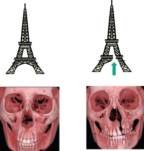
It can be hypothesised that the skulls of patients with unilateral complete cleft palate are susceptible to facial fractures because of the lack of the maxilla and palatal bone. It is therefore possible that when impacts are applied, larger areas will fracture in these skulls than in normal skulls. We conducted the present study to test this hypothesis and focused on orbital wall fractures, as these are among the most common seen in plastic surgery [Citation9–11].
Material and methods
Study of skulls
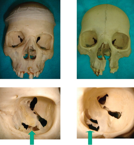
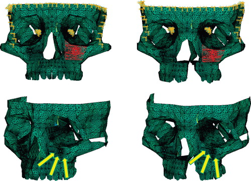
Waterhouse et al. produced orbital floor fractures by dropping a 394 g brass weight on the orbits of human cadavers [Citation12]. Referring to this experimental setting, we have developed an original experimental device (). A 400 g cylindrical brass weight slides inside a steel pipe and strikes objects (, left). The diameter of the weight is close to the internal diameter of the guide pipe, so the weight accurately strikes the region where the end of the pipe is placed (, right). Sixteen skulls were collected and divided into two groups. In the first group (n = 8), the skulls were used for the experiment without alteration. In the second group (n = 8), parts of the maxillas were removed to simulate the skulls in patients with unilateral complete cleft palate (). The groups were termed the intact skull group and cleft skull group, respectively. Impacts were applied to the left infraorbital rim of each skull using the original device, after which cracks developed on the orbital walls. The areas of the regions surrounded by these cracks were defined as actual fracture areas, and were measured. The actual fracture areas were compared with those in the intact skull group and the cleft skull group.
Figure 2. The experimental device used for the actual study. (Left) Each skull is fixed and placed under a stainless steel pipe. (Right above) The pipe is placed so that its lower end matches the inferior orbital rim. (Right below) The brass weight slides inside the pipe and strikes the inferior orbital rim.
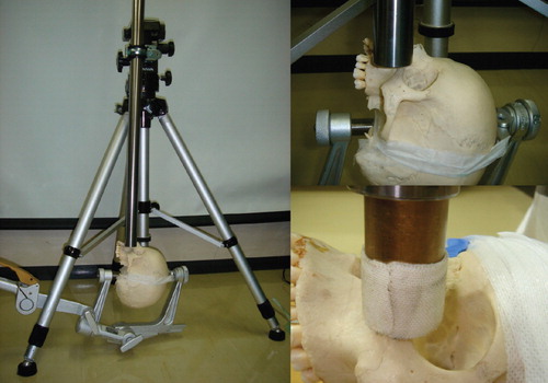
Figure 3. (Above left) Skulls with no deformity were included in the intact skull group. (Above right) Skulls in which the anterior part of the maxilla and hard palate were removed were included in the cleft skull group. (Lower row) Fractures occurring in the two models shown in the upper row. The areas enclosed by the fracture lines were defined as actual fracture areas (marked with arrows), and were measured for each model.
Production of simulation model
Among the patients who visited our hospitals between 2004 and 2008, 24 patients were included in the study. The experiment was first explained to the parents of the 24 patients, and their informed consent for inclusion in the study was obtained. Throughout the study, principles outlined in the Declaration of Helsinki were followed. Of the 24 patients, 12 had a unilateral complete cleft palate on the left side, and the other 12 had no congenital anomalies. All 24 patients had computed tomograms (CT) and computer aided design (CAD) models were produced.
First, CT images were obtained with 0.5 mm thickness (CB Works Hitachi Co., Ibaragi, Japan). They were saved as DICOM files at 300 dots per inch resolution. Then, 40-50 marking points were plotted on each axial slice of the CT to identify the bony components of the image. By connecting the marking points, a three-dimensional model was created. Production of the model and subsequent analysis were performed using structural analysis software (ANSYS 11.0, ANSYS Co., Canonsburg, PA, USA). According to Kopperdahl et al., the relation between the CT density of the bone and its Young's modulus is given as E = −34.7+3230QCT, where E and QCT mean the Young's modulus and CT density, respectively [Citation13]. Young's modulus is a value that indicates the stiffness of a particular material. It is defined as the ratio of stress to strain. For instance, when a stress with the intensity of X (N/m2) is applied to a material with Young's modulus of Y (N/m2), the material's response is compression in the ratio of X/Y.
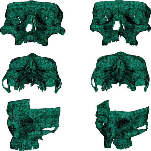
Based on Kopperdahl's formula, the Young's modulus of each skull was calculated and apportioned to the corresponding models. Poisson's ratio for each material was set referring to the data shown in a study by Pan et al. [Citation14]. Poisson's ratio is a value that indicates directional inter-relationships of a material's dynamic behaviour. For instance, when a material with 0.3 Poisson's ratio is expanded by 10% in the x-direction, the material shrinks by 3% in the y- and z-directions. Accordingly, the material properties shown in were apportioned to the corresponding parts of the models. Each model was divided into 110,000 to 128,000 shell elements. The models produced based on the CT images of the normal subjects and patients with cleft palates were classified as the intact model group (n = 12) and the cleft model group (n = 12), respectively ().
Table I. Material properties used for analysis.
Figure 4. Representative models designed by computer viewed from different angles for the intact model group (left column) and cleft model group (right column), respectively.
Application of load
Each model was fixed at its frontal and temporal regions. To simulate the destructive impact on the orbital region, energy was applied to each model. Ahmad et al. showed that 1.54 J were necessary to produce the orbital floor fracture with the buckling mechanism [Citation15]. Taking this into consideration, 1.8 J was applied to the inferior orbital rim of each model ().
Figure 5. Traumatic energy equivalent to 1.8 J was applied on the inferior orbital rims of the computed models of the intact model group (left column) and cleft model group (right column).
Calculation
Theoretical fracture area
As a result of the application of energy, stresses occur on the orbital walls of the models. Theoretically, fracture occurs in the regions where the stresses exceed the yielding stress of the bone. Our previous biomechanical study on skull fractures showed that the mean yielding stress of eight maxillas was 152 MPa [Citation16]. The areas of the regions where the stresses exceeded this value were measured, and were defined as theoretical areas of fracture.
Deviation of maxilla
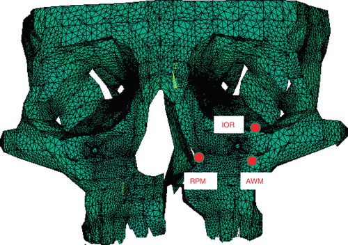
Three marking points were defined on the left side of the maxilla of each model (): IOR = inferior orbital rim; RPM = rim of the pyriform margin; and AWM = anterior wall of the maxilla — the point at which the horizontal plane crossing the RPM and the vertical plane crossing the IOR intersect with each other on the maxilla. The deviations of these three marking points on application of the impact were calculated.
Figure 6. Sites of the three marking points at which deviation was evaluated. IOR=inferior orbital rim; RPM=rim of the pyriform margin; and AWM=anterior wall of the maxilla.
Evaluation
Theoretical fracture area
Theoretical fracture areas were compared between the groups.
Dislocation of bilateral maxilla on loading
With each model, deviations of inferior orbital rim, rim of the pyriform margin, and anterior wall of the maxilla were compared between groups.
Statistical methodology
The actual fracture areas, theoretical fracture areas, and deviations of the marking points all showed skewed distribution. Therefore, the Mann-Whitney U-test was used for the comparison of these items. P-values less than 0.05 were considered statistically significant. All statistical calculations were performed using SPSS Version 10 for Windows (SPSS Inc., Chicago, USA).
Results
Actual skull study
Actual fracture areas were significantly greater (p < 0.0001) in the cleft skull group than in the intact skull group ().
Table II. Actual fracture areas (mm2) (n = 8 in each group).
Theoretical model study
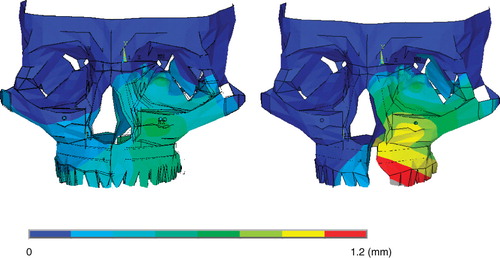
Representative patterns of theoretical fracture areas are shown in ; representative deformity patterns are shown in .
Figure 7. Representative patterns of the theoretical fracture areas (the areas of the regions where the stresses exceed the yield criterion of the bone: marked with red) for the intact model group (left column) and the cleft model group (right column), respectively.
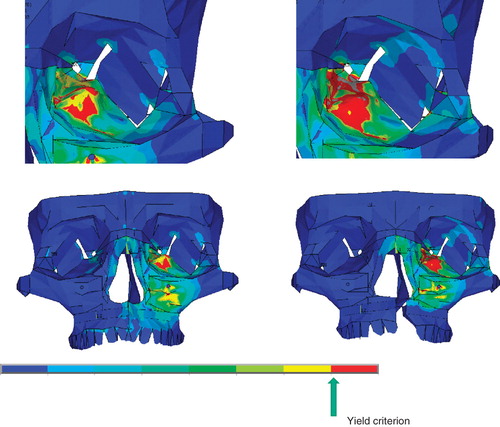
Figure 8. Representative patterns of maxillary deviation for the intact model group (left column) and cleft model group (right column), respectively. The maxilla deviates more in the cleft model group than in the intact model group.
Fracture area
Theoretical fracture areas were significantly greater (p < 0.0001) in the cleft model group than in the intact model group ().
Table III. Theoretical fracture areas (mm2) (n = 12 in each group).
Displacement of the marking points
For all three marking points, the displacements were greater in the cleft group than in the intact group ().
Table IV. Deviations of the marking points on impact (mm).
Discussion
Study background
The present study is to our knowledge the first to examine the relation between unilateral complete cleft palates and fractures of facial bones. Up to now, this relation has probably remained uninvestigated because unlike other related disorders — such as speech impediments and abnormal facial growth — there is no causal relation between unilateral complete cleft palate and fractures of facial bones.
This study was inspired by a question asked by the parents of a child with a unilateral cleft palate. The patient's father asked if he could teach his son martial arts. The father used the expression “cracked skull” for his son's skull, and asked if it was more likely to “split apart” than the skulls of normal children when the face was struck. We looked for evidence but found no answers to his question. Although cleft palate is one of the most common anomalies, it can be seen in only one in 500–1000 live births [Citation17,Citation18]. It is therefore unrealistic to attempt to evaluate the likelihood of fracture of a facial bone in patients with cleft palate by statistical studies.
However, parents of children with cleft palates are deeply concerned about the disability. It is therefore quite reasonable for these parents to ask such questions given by this father. Plastic surgeons dealing with patients with cleft palate have an obligation to answer these questions.
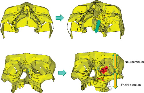
In the study on actual skulls, fractures occurred in larger areas in the cleft skull group than in the intact skull group, which is compatible with the finding of the theoretical model study, where the theoretical fracture areas were greater in the cleft model group than in the intact model group. Patients with unilateral complete clefts tend to develop more serious fractures than people with no abnormalities. The susceptibility of patients with unilateral complete cleft palate to fractures of the orbital floor can be hypothetically attributed to the discontinuity of the maxilla in these patients. The greater posterior deviations of the three marking points in the cleft model group than in the intact model group in the theoretical model study demonstrate the instability of the cleft-side maxilla of the patients with unilateral complete cleft palate. This instability is caused by dynamic independence of the cleft-side maxilla. Due to the lack of continuity between the non-cleft and cleft sides of the maxilla, the cleft-side maxilla deviates with less resistance in the posterior direction in response to external forces. The orbital walls work as the junction between the maxilla and the skull base. Therefore, as the maxilla moves backward, intensified stresses occur at the orbital walls, causing serious fractures there ().
Figure 9. In patients with cleft palate, the maxilla on the cleft side deviates in the posterior direction when impacts are applied (from left column to right column). The orbital walls constitute a junction between the facial cranium and the neurocranium (right below). Intensified stresses therefore occur on the orbital walls as the maxilla on the cleft side moves posteriorly (red regions).
If it is agreed that the discontinuity of the maxilla is the cause of the susceptibility to fractures of the orbital floor, unification of the cleft and non-cleft sides should present less deviation when impacts are applied. Orbital fracture is therefore expected to involve smaller areas. Unification of the two sides can be achieved by inserting a bone graft to fill the cleft — the alveolar bone grafting usually done for patients with alveolar clefts. Although the principal purpose of alveolar bone grafting is correcting the alignment of the alveolus [Citation19–21], it also reduces the risk of fractures of the orbital floor.
The present study focused on orbital fracture. However, in daily practice, plastic surgeons also encounter facial fractures of different types, such as zygomatic fractures or nasoethmoid fractures. The effect of cleft palate on these fractures must be studied further.
Acknowledgements
We thank Thane Doss for linguistic advice. Part of the present research was supported by the Grant for Traffic-Accident Related Clinical Research provided by the General Insurance Association of Japan.
Declaration of interest: The authors report no conflicts of interest. The authors alone are responsible for the content and writing of the paper.
References
- Khosla RK, Mabry K, Castiglione CL. Clinical outcomes of the Furlow Z-plasty for primary cleft palate repair. Cleft Palate Craniofac J 2008;45:501–10.
- Wolford LM, Cassano DS, Cottrell DA, El Deeb M, Karras SC, Goncalves JR. Orthognathic surgery in the young cleft patient: preliminary study on subsequent facial growth. J Oral Maxillofac Surg 2008;66:2524–36.
- Lee CT, Garfinkle JS, Warren SM, Brecht LE, Cutting CB, Grayson BH. Nasoalveolar molding improves appearance of children with bilateral cleft lip-cleft palate. Plast Reconstr Surg 2008;122:1131–7.
- Andrades P, Espinosa-de-los-Monteros A, Shell DH 4th, The importance of radical intravelar veloplasty during two-flap palatoplasty. Plast Reconstr Surg 2008;122:1121–30.
- Sari E, Ucar C, Türk O, Kurtulmus H, Ayberk Altug H, Pocan S. Treatment of a patient with cleft lip and palate using an internal distraction device. Cleft Palate Craniofac J 2008;45:552–60.
- Nagasao T, Miyamoto J, Yasuda S, An anatomical study of the three-dimensional structure of the nasal septum in patients with alveolar clefts and alveolar-palatal clefts. Plast Reconstr Surg 2008;121:2074–83.
- Costello BJ, Edwards SP, Clemens M. Fetal diagnosis and treatment of craniomaxillofacial anomalies. J Oral Maxillofac Surg 2008;66:1985–95.
- Kuriyama M, Udagawa A, Yoshimoto S, DNA methylation changes during cleft palate formation induced by retinoic acid in mice. Cleft Palate Craniofac J 2008;45: 545–51.
- Burm JS. Internal fixation in trapdoor-type orbital blowout fracture. Plast Reconstr Surg 2005;116:962–70.
- Kim KS, Kim ES, Hwang JH. Combined transcutaneous transethmoidal/transorbital approach for the treatment of medial orbital blowout fractures. Plast Reconstr Surg 2006;117:1947–55.
- Dal Canto AJ, Linberg JV. Comparison of orbital fracture repair performed within 14 days versus 15 to 29 days after trauma. Ophthal Plast Reconstr Surg 2008;24:437–43.
- Waterhouse N, Lyne J, Urdang M, Garey L. An investigation into the mechanism of orbital blowout fractures. Br J Plast Surg 1999;52:607–12.
- Kopperdahl DL, Pearlman JL, Keaveny TM. Biomechanical consequences of an isolated overload on the human vertebral body. J Orthop Res 2000;18:685–90.
- Pan X, Qian Y, Yu J, Wang D, Tang Y, Shen G. Biomechanical effects of rapid palatal expansion on the craniofacial skeleton with cleft palate: a three-dimensional finite element analysis. Cleft Palate Craniofac J 2007;44:149–54.
- Ahmad F, Kirkpatrick NA, Lyne J, Urdang M, Waterhouse N. Buckling and hydraulic mechanisms in orbital blowout fractures: fact or fiction? J Craniofac Surg 2006;17:438–41.
- Nagasao T, Miyamoto J, Nagasao M, The effect of striking angle on the buckling mechanism in blowout fracture. Plast Reconstr Surg 2006;117:2373–81.
- Siegel B. A racial comparison of cleft patients in a clinic population: associated anomalies and recurrence rates. Cleft Palate J 1979;16:193–7.
- Croen LA, Shaw GM, Wasserman CR, Tolarová MM. Racial and ethnic variations in the prevalence of orofacial clefts in California, 1983-1992. Am J Med Genet 1998;79:42–7.
- Russell KA, McLeod CE. Canine eruption in patients with complete cleft lip and palate. Cleft Palate Craniofac J 2008; 45:73–80.
- Pradel W, Tausche E, Gollogly J, Lauer G. Spontaneous tooth eruption after alveolar cleft osteoplasty using tissue-engineered bone: a case report. Oral Surg Oral Med Oral Pathol Oral Radiol Endod 2008;105:440–4.
- Dado DV, Rosenstein SW, Alder ME, Kernahan DA. Long-term assessment of early alveolar bone grafts using three-dimensional computer-assisted tomography: a pilot study. Plast Reconstr Surg 1997;99:1840–5.