Abstract
The icosahedral Polio virus capsid consists of 60 copies of each of the coat proteins VP1, VP2, VP3 and myristolyated VP4 (myrVP4). Catalyzed by the host cell receptor the Polio virus enters the host cell via externalization of myrVP4 and the N terminal part of VP1. There are several assumptions about the individual role of both of the proteins in the mechanism of membrane attachment and genome injection. We use the first 32 N terminal amino acids of VP1 and applied molecular dynamics simulations to assess its mechanism of function when attached and inserted into hydrated lipid membranes (POPC). Helical models are placed in various positions in regard to the lipid membrane to start with. As a comparison, the first 33 amino acids of the fusion peptide of gp41 of HIV-1 are simulated under identical conditions. Computational data support the idea that VP1 is not penetrating into the membrane to form a pore; it rather lays on the membrane surface and only perturbs the membrane. Furthermore, this idea is strengthened by channel recordings of both peptides showing irregular openings.
Introduction
Viruses enter the host by making the lipid membrane of the host permeable for their genome. The pathways used for entry are either to generate a pore and eject the viral DNA/RNA through the pore or to fuse viral and host membrane to release the entire interior of the virion into the host cell (Hogle Citation2002). The former strategy is mostly used by so-called naked viruses such as Polio virus and other members of the picornavirus family which wrap their genome with a shell of capsid proteins. The latter strategy is the route of entry for enveloped viruses such as human immunodeficiency virus type-1 (HIV-1), severe acute respiratory syndrome corona virus (SARS-Co) or influenza virus (Earp et al. Citation2005, Kielian and Rey Citation2006, Harrison Citation2008), which protect their genome with a lipid membrane. A common feature in these strategies is to seek the help of membrane active proteins. These proteins attach to the membrane and support the injection or fusion process in an oligomeric form. The injection pathway of Polio virus is investigated in this paper.
Polio virus uses the endocytotic pathway to hijack the host (Brandenburg et al. Citation2007). The capsid of Polio virus consist of 60 copies of each of four proteins VP1, VP2, VP3 and myristolyated VP4 (myrVP4) forming an icosahedral surface which contains the positive-sensed single-stranded RNA of approximately 7.5 kilobases. Each of the first three proteins is adopting an eight-stranded beta-barrel motif with a long N terminus (Bubeck et al. Citation2005). Inside the virion, the N termini of VP1 to VP3 together with myrVP4 form a network which stabilizes the capsid further. During entry, Polio virus binds to the cellular receptors Pvr (polio virus receptor) or CD155. Receptor interaction leads to conformational changes which involve externalization of parts of VP1 (Fricks and Hogle Citation1990) and myrVP4 (Chow et al. Citation1987, Kräusslich et al. Citation1990), changing the virion sedimentation characteristics from 160S to 135S particles when treated with proteases (De Sena and Mandel Citation1976). Both particles interact with lipid membranes altering the permeability (Tosteson and Chow Citation1997). The particular role for VP1 is assumed to be interacting with the membrane (Fricks and Hogle Citation1990) whilst myrVP4 is assumed to alter membrane permeability via the formation of pores (Danthi et al. Citation2003). This has led to the proposal of several potential routes of Polio virus entry (Bubeck et al. Citation2005). It is assumed that VP1 may not only act as linker to the receptor, but is also involved in pore formation forming a pentameric channel and stabilizing the virial capsid on the host membrane. On the other hand, looking at myrVP4, this viral protein seems to have a major role in RNA translocation and could also be a potential candidate forming a channel when assembling into a pentameric unit (see in Bubeck et al. Citation2005). Structural information of VP1 and myrVP4, in contact with the lipid membrane, are lacking to date.
HIV-1 uses the non-covalently linked gp120/gp41 proteins in a trimeric assembly to sense the target cell via gp120 and to support fusion with gp41 (Wyatt and Sodroski Citation1998). Upon interaction with the receptor a CD4 glycoprotein and chemokine co-receptors, CCR5 and CXCR4, gp120 undergoes conformational changes, which expose gp41 towards the cell membrane. During this step a hydrophobic region of approximately 33 N terminal residues called ‘fusion domain’ or ‘fusion peptide’ is able to interact with the host membrane. With estimated 15–20 trimeric units to be housed by the virion (Harrison Citation2008), only a single trimeric unit is suggested to be sufficient for fusion (Yang et al. Citation2006). The fusion peptide is reported to disorder the membrane lowering the energy barrier for membrane fusion (Tristram-Nagle et al. Citation2010). Early FTIR spectroscopic investigations unravel the transformation of the fusion peptide from a β-sheet conformation in solution into a helical motif in the presence of large unilamellar liposomes (Martin et al. Citation1996). NMR spectroscopic measurements (Wang Citation2008) in combination with fluorescence spectroscopy reveal a high helical content of the fusion peptide with an amount of β-sheet content when embedded in SDS micelles (Chang et al. Citation1997). Residues Ala-15 and Gly-16 are pointed out to induce a turn in the helix structure based on molecular dynamics (MD) studies done with structural data derived from NMR spectroscopy. Other studies confirm the helical content in similar experiments for residues Ile-4 up to Ala-22 when measuring a 30-amino acid peptide (Jaroniec et al. Citation2005). Most recent solid state 19-F NMR spectroscopy investigations on the fusion peptide report about irregular structure at the membrane at a very low peptide to lipid ratio (Grasnick et al. Citation2011). Solution NMR spectroscopic measurements confirm β-structure at high protein/lipid ratio (Li and Tamm Citation2007). MD simulations on the first 16 amino acids of the fusion peptide with an initial helical starting structure in the presence of a hydrated lipid bilayer show a tendency to penetrate into the bilayer maintaining the helical motif (Kamath and Wong Citation2002). To mimic surface tension, non-equilibrium MD simulations on dimers of the fusion peptide in a lipid bilayer have been performed (Barz et al. Citation2008). The simulations show an unfolding from an initial helical motif into an unordered peptide with short segments of β-structure and support experimental results from FTIR spectroscopy (Castano and Desbat Citation2005). The fusion peptide also seems to adopt a β-structure in the presence of the helical domain of T cell receptors (Bloch et al. Citation2007).
Albeit encoded by different types of viruses, the mode of action of the two proteins chosen in this study, VP1 from polio virus and gp41 from HIV-1, share some similarity (Bubeck et al. Citation2005, Harrison Citation2008). When both of the virions approach their individual host cell, the proteins are in a kind of pre-active state. Upon virion-host interaction, parts of the proteins unfold and may obviously get into contact with an aqueous environment for a short moment. The subsequent step after this is to interact with the lipid membrane. Any follow-up mechanism may then unfold into conceptually different routes of entry.
It is anticipated to elucidate the structural details of the interaction of VP1 N terminus along the line mentioned above using MD simulations and to compare the data with those derived for the fusion peptide of gp41. The data on the fusion peptide serve as an indicator of the reliability of the computational protocol as they can be compared with a series of experimental and computational data taken under almost identical conditions.
At this stage, the time frame of the biological event is longer than that on the basis of united atom computer simulation. Therefore, the overall process is fragmented into events which are assumed to be part of the overall movements of the proteins in vivo and can be treated as separate ‘events’. Due to the sensitivity of the starting structures for some ‘events’, more starting configurations are considered (up to four in some cases) as well as an extended simulation of up to 100 ns for some structures. In some cases the same configuration is run twice simultaneously in the same simulation box. All simulations have been evaluated regarding their constant fluctuation of the coordinates in respect to the starting structure.
In finding a compromise between receiving united atom information, screening of many starting structures as possible for a certain ‘event’, and allocating appropriate clock-time the length of the MD simulation has been chosen.
Experimental
The following sequence of the first 32 amino acids from the N terminus of the capsid protein VP1 (VP1-N) from Polio virus (Type 1, Mahoney strain, http://beta.uniprot.org/uniprot/P03300) were chosen for the simulations (Bubeck et al. Citation2005): GLGQMLESMI10 DNTVRETVGA20 ATSRDALPNT30 EA. The HIV-1 fusion peptide (FP1–33) of gp41 has been simulated with the following 33 amino acids AVGIGALFLG10 FLGAAGSTMG20 ARSMTLTVQA30 RQL (Bloch et al. Citation2007).
Computational methods
The Chou-Fasman algorithm (CFA) (Chou and Fasman Citation1974) for the prediction of the secondary structure of the peptides is used in its default mode.
Ideal helices were generated for both peptides (VP1: 287 atoms; FP1–33: 292 atoms) using MOE software (Molecule Operating Environment, www.chemcomp.com). The helices were either positioned close to or embedded to various degrees into equilibrated (70 ns (Krüger and Fischer Citation2008)) hydrated lipid (POPC, 16:0–18:1 Diester PC, 1-Palmitoyl-2-Oleoyl-sn-Glycero-3-Phosphocholine) bilayer systems consisting of either 128 or 256 lipid molecules (6,656 and 13,312 atoms, respectively). Care was taken to remove as little lipids as possible whilst embedding the peptides. In case of partial insertion with the need to remove lipids only from one leaflet, an inverted copy of the peptide was generated and inserted into the lipids as well. With this protocol it was guaranteed that the same number of lipid molecules was removed in both leaflets. Consequently such simulations contained two peptides of the same kind. The total number of atoms in the simulations was approximately 22,690 atoms when using a single peptide in the box and approximately 79,386 atoms when using two peptides in the box.
The peptide-lipid-water system was stepwise energy minimized using the steepest decent and conjugated gradient energy minimization. Each minimization was done for 400 steps with the peptides constrained (Krüger and Fischer Citation2008). A nanosecond MD simulation run followed, with the protein fully restrained. In one case, where two helices of VP1 were simultaneously fully embedded into one lipid patch, only 100 ps were chosen for the minimization run. This was done to avoid strong undulation effects of the lipid bilayer. The final production runs were calculated for 10 ns.
For all simulations GROMACS 3.3.1 was used together with the Gromos96 ffG45a3 force field. The step size of the simulation was 2 fs and all components of the system, protein, solvent and lipids were independently coupled with a Berendsen thermostat with a coupling constant of 0.1 ps and reference temperature 310 K. Two types of pressure couplings have been used: (i) Fully isotropic (iso) with a coupling time of 1.0 ps and a compressibility of 4.5 × 10⁻⁵ and (ii) semi-isotropic (semi) with coupling time of 0.1 ps, zero compressibility in the x-y plane and 4.5 × 10⁻⁵ in z-direction. Long range electrostatic interactions were calculated using the particle-mesh Ewald method (PME) with a grid size of 0.12 nm and interpolation order 4. Short range Coulomb interactions were cut off at 0.8 nm whilst the Lennard-Jones interactions were cut off at 1.4 nm.
All simulations were prepared an run on a DELL Inspiron 531S workstation, a 28-core Opteron-based compute cluster with Infiniband interconnects, and facilities of the National Center for High-Performance Computing (www.nchc.org.tw). Plots and pictures were generated using xmgrace, DSSP, and MOE.
Peptide synthesis
The following peptides were synthesized:
VP1-N-terminal amino acids 1–32: GLGQMLESMI10 DNTVRETVGA20 ATSRDALPNT30 EA (MWobs.: 3349 Da; MWcalc.: 3348.7 Da)
HIV-1 fusion peptide (FP1–33) of gp41: AVGIGALFLG10 FLGAAGSTMG20 ARSMTLTVQA30 RQL (MWobs.: 3267.3 Da; MWcalc.: 3266.9 Da) (Supplementary Figure 1, available online).
All peptides were synthesized at a 0.2 mmol scale on a custom-modified Applied Biosystems 433A peptide synthesizer using S-DVB (stryrene-divinylbenzene) resin carrying an -OCH2-PAM linker (Applied Biosystems, Foster City, CA, USA) and a thioester-generating linker following an in situ neutralization protocol for machine-assisted Boc (tert.-butoxycarbonyl) chemistry (Schnölzer et al. Citation1992, Camarero and Muir Citation2001). Side chain protecting groups were: Arg(Tos), Asn(Xan), Asp(OcHx), Glu(OcHx), Ser(Bzl) and Thr(Bzl). All synthetic peptides were released from their respective resins by treatment with liquid HF for 1 h at 0°C in the presence of 5% (v/v) p-cresol. 10 ml of liquid HF were used for 1 g of peptide-resin. Purification of peptide segments was achieved using a semipreparative RP-HPLC C4-column (Grace, Lokeren, Belgium) and combinations of different buffers: water + 0.1% TFA (buffer A); acetonitrile + 0.08% TFA (buffer B); isopropanol:acetonitrile:water 6:3:1 + 0.08% TFA (buffer C). Product containing fractions were identified by ESI-MS (electrospray ionization mass spectrometry) and pooled accordingly.
Channel recordings
Synthetic lecithins 1,2-dioleoyl-sn-glycero-3-phosphocholine (DOPC) and 1-palmitoyl-2-oleoyl-sn-glycero-3-phosphoethanolamine (POPE) (purity 99%) were purchased from Avanti Polar Lipids, Inc. (USA). The following chemicals and reagents were used in the experiments: KCl, trifluoroethanol (TFE), n-Hexane and HEPES from Sigma-Aldrich, Inc. (USA) and used without further purification. All of the reagents were dissolved in deionized water (resistivity of >16.8 MΩ cm-1) from Millipore, Inc. (USA). The buffer solutions were filtered through 0.22 μm Milex-GS filters from Millipore, Inc. (USA) prior to use.
A lipid mixture of POPE and DOPC (1:4 weight ratio) dissolved in n-hexane (10 mg/ml) was painted onto the aperture in the Delrin cup (diameter of aperture 150 μm) and dried under N2. The peptide, which was dissolved in trifluoroethanol (1 mg/1 ml), was also deposited on the aperture in the Delrin cup and dried under N2. The two chambers of the Delrin cup were then filled with buffer solution (500 mM KCL, 5 mM K+-HEPES, pH = 7.0). With a painting brush, the lipid/peptide mixture was transferred to covering the aperture of the Delrin cup (painting method, see also Chen et al. Citation2010).
The two chambers were connected to AgCl electrodes via Ag/AgCl/ agar bridges. The AgCl electrodes were connected with a BC-535 amplifier (Warners Instruments, USA). Bilayer formation was monitored electrically with the amplitude of the current pulse generated by a voltage ramp (typically a capacity of about 0.6 μF/cm2). The signal was passed through a low-pass 5 kHz and digitized by using a 1440A data acquisition system from Axon Instruments (Union City, USA) and the data were filtered with a Bessel-8-pole low-pass-filter at 100 Hz.
Results
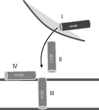
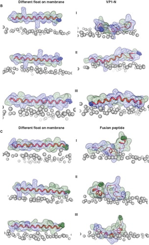
Several snapshots of the pathway of VP1 throughout its anticipated mode of action are envisaged in . VP1 is embedded in the capsid of the viron where it is predicted to adopt a helical conformation (Bubeck et al. Citation2005) (Stage I in ). When the virus interacts with the receptors of the host membrane the N terminus of the peptide is expected to move out of the capsid and passing the aqueous phase for a short period of time (Stage II, ). In the next step, VP1-N is then thought to either integrate into the membrane of the host (Stage III, ) or lay on the membrane surface (stage IV, ). FP1–33 is embedded in a trimeric gp41/gp120 complex (similar as Stage I of VP1). At the membrane the orientation of FP1–33 would be along the membrane surface. However, an insertion is also investigated in this study for comparison with the same stage for VP1-N (Stages III). A helical motif is adopted in each of the Stages II–IV for both proteins. Stage I is not further considered for both proteins in this study.
Figure 1. Schematic representation of the anticipated stages the N terminus of VP1-N from Polio virus may face during viral entry (stages I–IV). VP1-N encounters a virus bound stage (stage I, dark grey) which is not considered in this study. Stage II represents an aqueous environment, while the following stages represent the protein inserted into the membrane (stage III) or attached to the surface of the membrane (stage IV). Stages II–IV are represented by light grey rods. The arrow points from the N to the C terminus.
Secondary structure analysis
The Chou-Fasman algorithm (CFA) (Chou and Fasman Citation1974, Chen et al. Citation2006) used for the prediction of the secondary structure of the VP1 N terminus suggests two short helical segments: From Leu-2 to Ile-10 and from Asp-16 to Ala-21 (Supplementary Figure 1A, available online). Other prediction programs usually taken to assess the transmembrane domain (TMD) of a membrane protein (see for example Patargias et al. Citation2006, Krüger and Fischer Citation2009) do not indicate any region within the first 32 amino acids with a helical motif. DSSP analysis of VP1-N based on the last 3 ns of the simulations indicates that the first stretch assumed by CFA from Leu-2 to Ile-10 remains helical in all of the simulations independent of the starting configuration. The second helical stretch from Asp-16 to Ala-21 remains helical when the VP1-N is ‘more than half inserted’ in the lipid bilayer. Embedding the helix of VP1-N with its axis perpendicular to the membrane normal the helical stretch of VP1-N found in the simulations matches with the results from CFA. In some of the simulations the helix extends up to residue Thr-30. Applying the CFA to the sequence of FP1–33 reveals helical stretches from Ala-1 to Ala-14 and Ser-23 to Gln-32 (Supplementary Figure 1B, available online). In this region FP1–33 remains helical in all simulations but shows that this helical motif is not interrupted for residues Ala-15 to Arg-22. As a result the simulation pattern rather sees all the peptide in a helical motif.
When the helices are inserted into the membrane, a common temporarily adopted motif is a 5-helix (Supplementary Figure 2, available online). The length of the stretches of this motif varies in the individual simulation but can be as long as 11 amino acids as in the case of over a half inserted VP1-N (semi) (Figure VP1, over half semi). In some simulations a 3,10 helix motif stretching over up to 5 residues is observed for a very short time. In several occasions the 3–10 helix motif flickers into a turn motif (Figure VP1 fully, iso). In one occasion, when FP1–33 is half way inserted into the bilayer a β-sheet motif is adopted between residues Ala-14 to Ser-16 (AAGS) and Thr-18 to Ala-21 (TMGA) (Figure FP1-33 half in iso). The β-sheet motif is temporarily disrupted by turns, beta bridges and bends. Albeit, β-bridges are rare in all the simulations, they are detected in FP1–33.
The proteins
The root mean square deviation (RMSD) of the Cα atoms of the peptides, in regard to the starting structure, is large when the helices of both, VP1-N and FP1–33, are in contact with the aqueous phase (, I–III and , ). The values range from about 0.8 nm (VP1-N, , ; FP1–33, , II) to about 1.0 (VP1-N, , III). FP1–33 even shows a value of about 1.2 nm (, ). The values rise high, especially when the peptides are just touching the membrane independent of whether the helices are aligned parallel (, ) or perpendicular (about 0.8 for FP1–33, , ) to the membrane normal. Values below 0.8 nm are obtained when the helices are fully inserted into the membrane (, IV, and , III). After a short initial rise the values for these positions remain constant over the entire duration of the simulations. There is a tendency that the values for VP1 are higher than the values for gp41 when fully inserted into the membrane, either parallel (about 0.6 nm for VP1-N versus about 0.5 nm for FP1–33, , IV) or perpendicular to the membrane normal (about 0.7 nm for VP1-N versus about 0.3 nm for FP1–33, , III). Extended simulations of up to 100 ns for a deeper than half embedded (, III) and fully inserted peptide (, IV) show a continuation of the RMSD values in the same range as identified for the first 5–10 ns of each of these particular simulations (, V). All observations of the proteins () within the framework of the experimental setup are independent of the type of pressure coupling used.
Figure 2. Root mean square deviation (RMSD) of the Cα backbones of the peptides referring to the starting structure. Data for VP1-N and FP1–33 are shown in the left and right columns, respectively. The rows are aligned to represent a gradual insertion of the peptides into the lipid membrane. Helices are aligned either parallel (A) or perpendicular (B) to the membrane normal. For parallel alignment (A): (I) touches the membrane, (II) half inserted, (III) deeper than half in the membrane, (IV) fully inserted into the membrane and (V) extended 100 ns MD simulations for alignments (III) and alignment (IV) with Run1 of VP1-N and Run2 of FP1–33. For perpendicular alignment (B): (I) float on membrane, no lipid molecules are removed, (II) embedded in one leaflet, and (III) fully embedded in middle of membrane. For the latter two cases lipid molecules are removed. Peptides A and B represent two peptides of the same kind simulated in a single membrane. Runs 1 and 2 are the same simulation box run twice. For the simulations semi isotropic pressure coupling has been used.
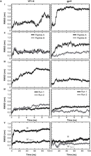
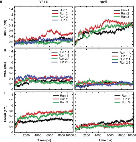
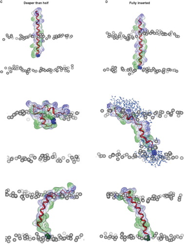
Figure 3. Snapshots of VP1-N and FP1–33 at various starting-positions in respect to the lipid bilayer: N-terminus towards the membrane (A), half inserted (B), deeper than half in the membrane (C) and fully inserted (D). Each panel shows VP1-N at 0 ns (top) and 10 ns (middle), as well as FP1–33 at 10 ns (bottom) for (A) and (B). (C) and (D) show structures after 100 ns instead of 10 ns. The protein backbone is shown in red, the side chains in stick modus and transparent van der Waals spheres. VP1-N-Gly-1 and FP1–33-Ala-1 are shown in blue and green, respectively, van der Waals spheres. Boundaries of the lipid bilayer are represented by the phosphorous atoms of the lipid headgroups (grey spheres). Water molecules are shown as blue triangles in a ball-stick modus. Graphics are generated using MOE.
The following representative cases are shown in .
(i) N-terminus touches the membrane
Two simulations of each of the peptides are generated due to the use of isotropic and semi-isotropic pressure coupling. The simulations of VP1-N and FP1–33 start with the peptides in an α-helical conformation exposed to the aqueous environment pointing their N termini towards the lipid membrane (). During 10 ns of MD simulation Gly-1 of VP1 dives into the hydrophobic slab of the lipid membrane. The helix of VP1-N partially unwinds but remains almost stretched. The N terminus of FP1–33 does not penetrate the level of phosphorous atoms of the lipid membrane. The helix unwinds between residues Met-9 and Arg-24 and adopts a globular shape due to the large number of hydrophobic residues which minimize their contacts with the aqueous environment.
(ii) N-terminus half inserted
When placing the peptides with their N termini into the hydrophobic slab so that the first residue of each peptide is within one leaflet of the bilayer (), the N terminus remains in the same half of the leaflet for both peptides. The termini rather approach the head group region. This leads to a strong tilt of the helix of VP1-N accompanied with some unwinding. The hydrophilic residue such as Glu-7 and Ser-8 interact with the phosphorous and glycol residues. The residues on the outside of the membrane also aim for interactions with the head group region; especially here, the negatively charged residues interact with the choline part of the head groups. For FP1–33, the hydrophilic residues Thr-27 and Arg-22 interact with the head group region leading to a collapse of the extended structure. It is also observed that FP1–33 stretches further into the membrane towards the head group region of the opposite leaflet.
(iii) N-terminus deeper than half
Differences occur between the two peptides with the deeper insertion of the peptides into the hydrophobic slab (). In both simulations (using iso and semi isotropic pressure coupling), the N terminus of VP1-N aims towards the head group region of the same leaflet it is positioned in. As a consequence, the helical structure collapses into a scissors-like shape ‘squeezing’ the lipid head groups. Hydrophilic residues such as Glu-7, Ser-9, Thr-13 and Arg-15 interact with the head group region from the hydrophobic slab whilst Thr-22, Ser-23, Arg-24 and Asp-25 interact with the head groups from the aqueous phase according to their original positions. In a 100 ns MD simulation, the section Val-18 to Arg-24 unwinds to generate the ‘kink’. The hydrophobic slab of FP1–33 remains in an almost helical form and eventually stretches into a 3,10 helix, reaching out for the head group region of the opposing leaflet.
(iv) N-terminus fully inserted
When fully inserted into the membrane after 100 ns MD simulation, VP1-N undergoes partial unwinding due to the positioning of hydrophilic residues in the hydrophobic slab (). Specifically, the C terminal part from Asp-23 onwards interacts with the head group region. At the N terminal side, Gln-4 and Glu-7 disturb the bilayer so that the head groups are dragged deeper into the hydrophobic slab. Overall the disturbance of the membrane is such that over the entire stretch of the peptide, water molecules are present also within the hydrophobic slab. On the other hand, FP1–33 remains almost fully intact with anchoring the helix via Arg-22 into the head group region.
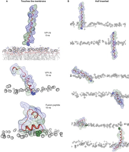
Floating on membrane, embedded in the head group region, fully embedded and different floats on the membrane
Whilst floating on top of the head group region as a helix, some unwinding occurs in both peptides (). The helices remaining, match the Guy-Faseman prediction results. The rotational orientation of the helices in is chosen in such a way that most of the hydrophobic residues point towards the bilayer. Using different rotational orientations of the helices (steps of approximately 90°) with regard to the membrane surface VP1-N tends to retain its helical structure to a larger extend () than FP1–33 (). The latter peptide seems to rather curl to avoid the aqueous phase.
Figure 4. Snapshots of VP1-N and FP1–33 positioned with the helix axis parallel to the membrane surface named ‘floating on membrane’ (A). Snapshots of the peptides floating on the membrane at different rotations: VP1-N (B) and FP1–33 (C). For both peptides the left panel represents the conformation at 0 ns, the right panel the conformation after 10 ns, both peptides half (D) and fully inserted (E). The protein backbones are shown in red, the side chains in stick modus and transparent van der Waals spheres. Each panel shows VP1-N at 0 ns (top) and 10 ns (middle), as well as FP1–33 at 10 ns (bottom). VP1-N-Gly-1 and fusion-peptide-Ala-1 are shown in blue and green, respectively, van der Waals spheres. Boundaries of the lipid bilayer are represented by the phosphorous atoms of the lipid head groups (grey spheres). Graphics are generated using MOE.
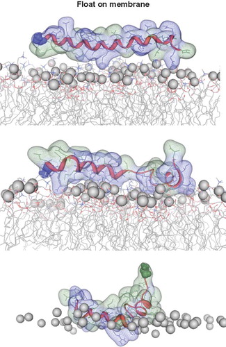
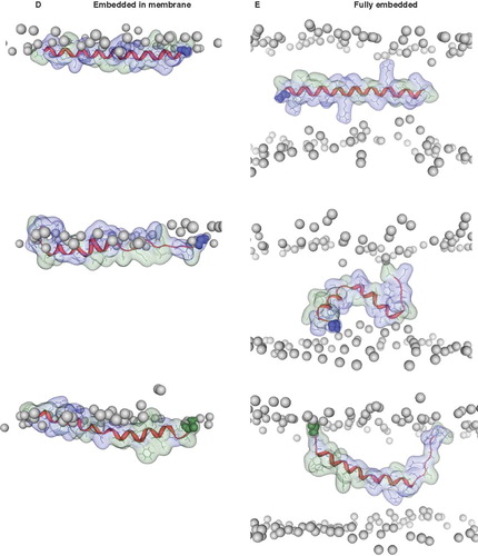
Embedding the helices into the lipid head group region (with the hydrophilic residues towards the hydrophobic slab) leads to a strong unwinding of VP1-N towards its N terminal side (). According to the high number of hydrophobic residues, FP1–33 remains helical with Ala-1 snorkeling for the head group region. Phe-8 is tearing towards the hydrophobic slab and seems to take parts of the helix to each side with it.
When fully embedded into the hydrophobic slab it appears that the helix of both peptides remains intact despite considerable changes in orientation (). The charged ends snorkel for the hydrophilic head groups with the consequence of either curling as in the case of VP1-N, or remain stretched as in FP1–33. VP1-N adopts a kinked helix with two segments remaining helical from residues Leu-2 to Met-8 and Val-14 to Arg-24.
It is suggested that VP1-N may rather not like to insert into the lipid membrane since its orientation is such a shape that it aims to squeeze into the lipid head group region of one leaflet. FP1–33 prefers to search for the membrane to remain inside. When floating on the membrane VP1-N remains fairly helical, implying this orientation as preferred by the peptide.
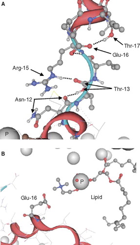
Inspections of individual frames of VP1-N, fully inserted and fully embedded (both taken from ) reveal insights of the behavior of hydrophilic residues within the lipid bilayer (). If no hydrophilic partner is available, the side chain of Thr-13 forms hydrogen bonds with the backbone carbonyl of Asn-12 leading to a rupture of the helical motif at this site (). The longer hydrophilic side chains are able to form hydrogen bonds with either another side-chain (e.g., Glu-16 with Thr-17) and simultaneously with a backbone NH-group (e.g., Glu-16 with Arg-15) or a carbonyl group (e.g., Arg-15 with Thr-13). In a hydrophobic environment, hydrophilic residues tend to minimize the exposure to the unfavorable environment by forming ‘bridged’ connections to compensate the energetic penalty of the charges. In another simulation, if no partner for a salt bridge or hydrogen bonding is available, the lipid molecules can be bent towards the center of the bilayer (, ). Glu-16 of VP1 fully embedded attracts a lipid molecule and bends it so that its acetylcholine group interacts with the carboxylate group of Glu-16. Hydrophobic residues outside the lipid bilayer will not penetrate the lipid head group region, but prefer to induce a spherical shape of the peptide (hydrophobic effect). The data suggest a concerted mechanism of peptide and lipid during protein mechanics.
Figure 5. Representative conformations of VP1-N from the MD simulations when fully inserted (A) and fully embedded (B). Peptide backbone is shown in red, the side chains in ball and stick representation. Nitrogen atoms are shown in blue, oxygen atoms in red. The phosphorous atoms of the lipid molecules are represented by grey spheres. Graphics are generated using MOE.
The lipids
In some cases only lipids of one leaflet are removed to enable the insertion of the peptide into the bilayer. In this case a similar number of lipids are removed from the opposing leaflet. The generated hole is then filled with the same peptide. As a consequence, the same number of lipids is removed in both leaflets. This protocol is followed to maintain a similar lateral stress profile for each leaflet. In a representative simulation following the protocol mentioned, the lipid density calculated for each leaflet of the starting (at 0 ns, black lines in Supplementary Figure 3A, available online) and final (at 10 ns, red lines in Supplementary Figure 3A) frames show almost the same values indicating that during the simulation the lipid density for each of the leaflets remain identical. The position of the phosphorous atoms averaged over all lipids in each leaflet of the system indicates the thickness of the bilayer. Calculating lipid thickness for selected time frames reveals the membrane system retaining its membrane dimensions (Supplementary Figure 3B, available online). Similar behavior in respect of lipid density and thickness is observed for all simulations (data not shown).
Experimental data
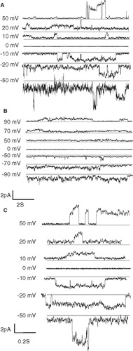
Channel recordings of VP1-N reconstituted into artificial lipid bilayer at various holding potentials (from +50 to −50 mV) reveal no concerted openings which should lead to rectangular shaped current patterns of ion channels (). The estimated conductance from some openings vary from 8 pS (recorded at +50 mV) to 100 pS (recorded at +10 mV) when positive voltage is applied and 60 pS (recorded at −50 mV) to 160 pS (recorded at −10 mV) when negative voltage is applied. The observed high conductance at negative potential indicates that the peptide is accumulated on one side of the membrane due to the preparation protocol (see Materials and methods). Selected openings show a gradual current increase indicative for a slow process with a high degree of cooperative events (see arrows in traces at + /−10 mV and −20 mV of ). When an opening level is reached, the opening remains heavily fluctuating. As a comparison, insertion of FP1–33 into the lipid membrane, does not result in opening events it rather results in irregular constant current fluctuations (). The recorded data are similar if FP1–33 is ‘flashed’ with a pipette towards the membrane (data not shown). When ‘flashing’ VP1 against the membrane no channel recordings are observed. Channel recording data are indicative for the property of VP1-N disturb the membrane rather than forming defined assemblies which lead to gated pores.
Figure 6. Channel recordings of VP1 (A) and FP1–33 (B) inserted into artificial lipid bilayers at various holding potentials. Selected traces of the recordings with VP1 are outlined (C). Grey lines in the recordings indicate the lowest detected current rather than marking the zero current line of the recordings.
Discussion
Structural details about VP1-N approaching and interacting with the lipid membrane are missing. MD simulations are used to assess the structural features and potential orientation of the peptide on the lipid membrane, an approach which has been reported for other peptides such as alamethicin and melittin (La Rocca et al. Citation1999). In most of the cases, the starting configuration is a helical motif and its integrity is then observed during the simulation. For most membrane active peptides of bacterial and viral origin the helical motif has been confirmed experimentally (reviewed in (Bechinger Citation1997, Cook et al. Citation2011)). In this study we follow this line since VP1-N is proposed to be helical when attached to the capsid of the virion as a 160S particle (Bubeck et al. Citation2005). It is assumed that through the ‘short’ period of time, when exposed to an aqueous phase, if at all, the conformation remains helical. The motivation to run simulations under similar conditions with FP1–33 is to have a kind of reference at hand. For the fusion peptide, structural motifs in various environments are known and the computational results can be compared with these data.
Since it has been suggested that VP1-N could be traversing the membrane to line a pore channeling the genome into the cell, secondary structure prediction programs for TMDs including CFA have been used to obtain information about a helical motif of the peptide. The prediction of helical motifs by the CFA is based on the statistical appearance of amino acids of globular proteins in certain secondary structure motifs. The algorithms used to predict TM helices in membrane proteins (e.g., see Patargias et al. Citation2006, Fischer and Krüger Citation2009) assess the frequentness of the appearance of hydrophobic residues within the primary sequence of a membrane protein and then assume a helical motif for this particular stretch. Predicted helical stretches by GFA are therefore most likely to appear when a VP1 N terminus is located within the capsid and should not necessarily suggest a TM spanning motif. In the case of FP1–33, the two helical stretches may represent this motif to be adopted when the peptide is in the pre-fusion state. In most of the simulations the helical motifs remain intact. In the configuration of VP1-N touching the membrane and half inserted, the second helical motif towards the C terminal side unwinds, which does not occur in the case of FP1–33. This may be an indication that in the case of contact with the aqueous phase VP1-N undergoes some unwinding. As today it is not yet elucidated whether VP1-N is exposed to the aqueous phase, the lack of any helical results by the other programs can be taken as a hint that the peptides do not form helical motifs within the lipid membrane.
The RMSD data show that peptides integrated into the lipid membrane adopt low values which do not fluctuate very much. The values for peptides positioned in a different environment deviate considerably from the starting structures. Consequently, for some peptides the structures are fairly well equilibrated whilst for others no equilibration has been achieved. Therefore, it is considered to see the structures after a 10 ns simulation not necessarily equilibrated. With some of the structures well equilibrated and also run for 100 ns an assessment of stability of the peptides and the consequences on the biological mechanism of function is undertaken.
The interaction of the peptide with the lipids leading to large disturbance of the peptide conformation and the lipid alignment is a commonly found motif in MD simulations (La Rocca et al. Citation1999). Disorder of lipids in the presence of peptides has also been reported for the antimicrobial peptide melittin (Bachar and Becker Citation2000). Also unfolding of the peptide is a pattern found for simulations with other membrane-bound peptides such as a selected sequence of the myelin basic protein (Polverini et al. Citation2010). Lipid distortion and with it the formation of water pockets is found for charged amino acids when they are located at various sites within a lipid bilayer (MacCallum et al. Citation2008).
Starting from a helical conformation and positioned with the helix axis parallel to the membrane normal, FP1–33 indicates that an even deeper insertion follows during the simulation (see half inserted and deeper than half). The helical motif remains almost intact and matches MD simulations of other groups (Kamath and Wong Citation2002). Development of extended β-sheet structure is not observed similar to assumptions from experimental studies (Chang et al. Citation1997, Li and Tamm Citation2007, Qiang and Weliky Citation2009). Intensive unwinding is only observed when the peptide is exposed to the aqueous environment above the lipid membrane (float on membrane). This unwinding could display a conformational precursor for forming a larger assembly with β-sheet structure (Schmick and Weliky Citation2010). VP1-N shows the tendency to remain at the border of the aqueous phase and the lipid head group region. When positioned like ‘floating on membrane’ and ‘inside the membrane’ VP1-N is hardly unwinding due to its hydrophilic character. This is seen to be in contrast to the strong bend of VP1-N when inserted ‘deeper than half’. Fully inserted VP1-N remains helical. Thus, an insertion mechanism such as going from ‘deeper than half’ to ‘fully inserted’ may not be favorable for the peptide.
The data support conservation of helical motifs in each of the two peptides when both are fully inserted independent of the pressure coupling scheme used. For VP1-N it is rather a pulling out of the membrane than an unwinding of the helix. Furthermore, the generation of a β-sheet motif of the fusion peptide rather due to protein-protein interactions then due to the lipid environment alone (Bloch et al. Citation2007).
Maintenance of the helical motif or even adopting it has been reported using computer simulations (Ulmschneider et al. Citation2010a, Citation2010b). The simulations support the suggestion of the formation (Popot and Engelman Citation1990) and existence of the transmembrane helical motif. The presented results are in agreement with these simulations (Ulmschneider et al. Citation2010a). In the case of FP1–33, only half inserted it remains as a helix and moves deeper into the bilayer. However, when inserted ‘deeper than half’ into the lipid membrane the N terminus is ‘snorkeling’ for the head groups of the opposing leaflet, rupturing the helical motif towards the N terminal side. This happens because of the strong driving force of the N-terminus to integrate into a polar or aqueous environment. For VP1-N, (deeper than half) the two helical segments remain at the N terminal side moving from the lipid phase to the head groups and the C terminal side from the aqueous phase towards the head groups. The movement within the lipid phase is due to the lack of hydrophobic residues towards the N terminal side. When ‘fully inserted’, VP1-N leads to an enormous distortion of the membrane potentially leading to a leakage of the cell since water molecules are distributed close to the peptide across the membrane.
Still to be explored is the stability of helical motifs at the level of the head group region with the same length of simulations as reported in Ulmschneider et al. (Citation2010a). In the light of the agreements of the present simulations with others (Benz et al. Citation2006), and as mentioned above, it is concluded that the results, such as VP1-N remaining fairly helical when aligned with the helical axis perpendicular to the membrane normal and ‘inside’ as well as the observed unwinding of FP1–33 in most of the cases, are relevant. Despite the limited duration of the simulations, FP1–33 adopts motifs which are observed experimentally (Martin et al. Citation1996, Chang et al. Citation1997, Jaroniec et al. Citation2005, Wang Citation2008). An extended β-fold has been suggested either in the presence of cholesterol (Zheng et al. Citation2006, Bodner et al. Citation2008) or high peptide content (Li and Tamm Citation2007, Qiang and Weliky Citation2009). This strengthens the interpretation of the data obtained for VP1-N further. Thus, biological implications of the simulation results can be drafted.
Biological implications
Several scenarios have been proposed for the mode of action of VP1-N in concert with myrVP4 to enable the injection of viral RNA through the lipid membrane of the endosome into the cytoplasm of the host cell. In an earlier study it has been suggested that VP1 is solely responsible as a pentameric unit to channel the RNA across the lipid membrane (route I, (Hogle Citation2002) and and B in Bubeck et al. Citation2005). Another proposition is that VP1-N and myrVP4 act in concert (route II, in Bubeck et al. Citation2005), with both of them within the lipid membrane. More recent investigations suggest that myrVP4 is the sole constituent within the membrane during viral entry (route III, in Bubeck et al. Citation2005). Based on the short simulations, it is likely that VP1 does not penetrate into the membrane. This makes route I and II unlikely and is rather in favor of route III. Thus, VP1 could be engaged in stabilizing the virion on the membrane by floating on the membrane, eventually pointing away from the transmembrane myrVP4 protein assembly. It may also be involved in alternating membrane stress profiles and lipid dynamics around VP4 assembly.
Experimental data are supporting the idea of VP1 not integrating into the membrane. Once integrated the recordings show a broad current distribution and severe fluctuation which rather encourages the idea of membrane disturbance rather than forming structurally well designed and stable conducting channels. The recordings are distinct from those reported on the viron capsid in contact with artificial lipid bilayers (Danthi et al. Citation2003). It has been shown that channel recordings depend on mutations of myrVP4 and therefore it is concluded that this protein is part of the architecture of the channel. The membrane disturbance is even more pronounced when FP1–33 is added to a lipid membrane and similar to those disturbances reported earlier when the fusion peptide is reconstituted into artificial lipid bilayers (Slepushkin et al. Citation1990). Therefore it is proposed that VP1-N is more likely to attach to the membrane rather than forming defined channels or pores.
Conclusion
Short simulations of the N-terminal part of VP1 have been undertaken to assess the potential mode of action during viral entry. Based on the positioning of VP1-N in different environments mimicking viral entry, it is suggested that VP1-N is not penetrating into the membrane by aligning with its helical axis parallel to the membrane normal during viral entry to form a channel. The protein rather alters membrane characteristics in support of myrVP4 insertion, assembly and pore formation.
Supplementary Figures 1–4
Download MS Word (1.8 MB)Acknowledgements
We thank Yechiel Shai (Rehovot, IL, USA) for valuable discussions and critically reading the manuscript. WBF thanks the NYMU and the government of Taiwan for financial support (Aim of Excellence Program) and the National Center for High-Performance Computing for providing computer time. This work was supported by the National Science Council (NSC) of Taiwan (NSC98-2112-M-010-002-MY3). JK acknowledges a fellowship granted by the Alexander von Humboldt-Foundation and the NSC. CPC acknowledges a fellowship of the DAAD and a Taiwan-German Scholarship.
Declaration of interest: The authors report no conflicts of interest. The authors alone are responsible for the content and writing of the paper.
References
- Bachar M, Becker OM. 2000. Protein-induced membrane disorder: A molecular dynamics study of melittin in a dipalmitoylphosphatidylcholine bilayer. Biophys J 78:1359–1375.
- Barz B, Wong TC, Kosztin I. 2008. Membrane curvature and surface area per lipid affect th conformation and oligomeric state of HIV-1 fusion peptide: A combined FTIR and MD simulation study. Biochim Biophys Acta 1778:945–953.
- Bechinger B. 1997. Structure and functions of channel-forming peptides: Maganins, cecropins, melittin and alamethicin. J Membr Biol 156:197–211.
- Benz RW, Nanda H, Castro-Román F, White SH, Tobias DJ. 2006. Diffraction-based density restraints for membrane and membrane-peptide molecular dynamics simulations. Biophys J 91:3617–3629.
- Bloch I, Quintana FJ, Gerber D, Cohen T, Cohen IR, Shai Y. 2007. T-cell inactivation and immunosupressive activity induced by HIV gp41 via novel interacting motif. FASEB J 21:393–401.
- Bodner ML, Gabrys CM, Struppe JO, Weliky DP. 2008. 13C-13C and 15N-13C correlation spectroscopy of membrane-associated and uniformly labeled human immunodeficiency virus and influenza fusion peptides: Amino acid-type assignments and evidence for multiple conformations. J Chem Phys 128:052319–052311.
- Brandenburg B, Lee LY, Lakadamyali M, Rust MJ, Zhuang X, Hogle JM. 2007. Imaging poliovirus entry in living cells. PLOS Biol 5:1543–1555.
- Bubeck D, Filman DJ, Cheng N, Steven AC, Hogle JM, Belnap DM. 2005. The structure of the Poliovirus 135S cell entry intermediate at 10-Angstrom reslution reveals the location of an externalized polypeptide that binds to membranes. J Virol 79:7745–7755.
- Camarero JA, Muir TW 2001. Native chemical ligation of polypeptides. Curr Protocols Prot Sci 18:14.11–14.21.
- Castano S, Desbat B. 2005. Structure and orienation study of fusion peptide FP23 of gp41 from HIV-1 alone or inserted into various lipid membrane models (mono-, bi- and multibi-layers) by FTIR spectroscopies and Brewster angle microscopy. Biochim Biophys Acta Biomembr 1715:81–95.
- Chang D-K, Cheng S-F, Chien W-J. 1997. The amino-terminal fusion domain peptide of human immunodeficiency virus type 1 gp41 inserts into the sodium dodecyl sulfate micelle primarily as a helix with a conserved glycine at the micelle-water interface. J Virol 71:6593–6602.
- Chen CP, Kremer C, Henklein P, Schubert U, Fink RHA, Fischer WB. 2010. Modulating the activity of channels formed by a short segment of the Vpr protein from HIV-1. Eur Biophys J 39:1089–1095.
- Chen H, Gu F, Huang Z. 2006. Improved Chou-Fasman method for protein secondary structure prediction. BMC Bioinformatics 7(Suppl. 4):S14.
- Chou PY, Fasman GD. 1974. Prediction of protein conformation. Biochemistry 13:222–245.
- Chow M, Newman JF, Filman DJ, Hogle JM, Rowlands DJ, Brown F. 1987. Myristylation of picornavirus capsid protein VP4 and its structural significance. Nature 327:482–486.
- Cook GA, Zhang H, Park SH, Wang Y, Opella SJ. 2011. Comparative NMR studies demonstrate profound differences between two viroporins: p7 of HCV and Vpu of HIV-1. Biochim Biophys Acta 1808:554–560.
- Danthi P, Tosteson M, Li Q-H, Chow M. 2003. Genome delivery and ion channel properties are altered in Vp4 mutants of poliovirus. J Virol 77:5266–5274.
- De Sena J, Mandel B. 1976. Studies on the in vitro uncoating of polio virus. I. Characterization of the modifying factor and the modifying reaction. Virology 70:470–483.
- Earp LJ, Delos SE, Park HE, White JM. 2005. The many mechanisms of viral membrane fusion proteins. Curr Top Microbiol Immunol 285:25–66.
- Fischer WB, Krüger J. 2009. Viral channel forming proteins. Int Rev Cell Mol Biol 275:35–63.
- Fricks CE, Hogle JM. 1990. Cell-induced conformational changes in poliovirus: Externalization of the amino terminus of VP1 is responsible for liposome binding. J Virol 64:1934–1945.
- Grasnick D, Sternberg U, Strandberg E, Wadhwani P, Ulrich AS 2011. Irregular structure of the HIV fusion peptide in membranes demonstrated by solid-state NMR and MD simualtions. Eur Biophys J 40:529–543.
- Harrison SC. 2008. Viral membrane fusion. Nature Struc Mol Biol 15:690–697.
- Hogle JM. 2002. Poliovirus cell entry: Common structural themes in viral cell entry pathways. Annu Rev Microbiol 56:677–702.
- Jaroniec CP, Kaufman JD, Stahl SJ, Viard M, Blumenthal R, Wingfield PT, Bax A. 2005. Structure and dynamics of micelle-associated human immunodeficiency virus gp41 fusion domain. Biochemistry 44:16167–16180.
- Kamath S, Wong TC. 2002. Membrane structure of the human immunodeficiencey virus gp41 fusion domain by molecular dynamics simulations. Biophys J 83:135–143.
- Kielian M, Rey FA. 2006. Virus membrane-fusion proteins: More than one way to make a hairpin. Nature Rev Microbiol 4:67–76.
- Kräusslich H-G, Hölscher C, Reuer Q, Harber J, Wimmer E. 1990. Myristoylation of the poliovirus polyprotein is required for proteolytic processing of the capsid and for viral infectivity. J Virol 64:2433–2436.
- Krüger J, Fischer WB. 2008. Exploring the conformational space of Vpu from HIV-1: A versatile and adaptable protein. J Comp Chem 29:2416–2424.
- Krüger J, Fischer WB. 2009. Assembly of viral membrane proteins. J Chem Theory Comput 5:2503–2513.
- La Rocca P, Biggin PC, Tieleman DP, Sansom MSP. 1999. Simulation studies of the interaction of antimicrobial peptides and lipid bilayers. Biochim Biophys Acta 1462:185–200.
- Li Y, Tamm LK. 2007. Structure and plasticity of the human immunodeficiency virus gp41 fusion domain in lipid micelles and bilayers. Biophys J 93:876–885.
- MacCallum JL, Bennett WFD, Tieleman DP. 2008. Distribution of amino acids in a lipid bilayer from computer simualtions. Biophys J 94:3393–3404.
- Martin I, Schaal H, Scheid A, Ruysschaert J-M. 1996. Lipid membrane fusion induced by the human immunodeficiency virus type 1 gp41 N-terminal extremity is determined by its orientation in the lipid bilayer. J Viol 70:298–304.
- Patargias G, Zitzmann N, Dwek R, Fischer WB. 2006. Protein-protein interactions: Modeling the hepatitis C virus ion channel p7. J Med Chem 49:648–655.
- Polverini E, Coll EP, Tieleman DP, Harauz G. 2010. Conformational choreography of a molecular switch region in myelin basic protein – molecular dynamics shows induced folding and secondary structure type conversion upon threonyl phosphorylation in both aqueous and membrane-associated environments. Biochim Biophys Acta 1808:674–683.
- Popot J-L, Engelman DM. 1990. Membrane protein folding and oligomerization: The two-stage model. Biochemistry 29:4031–4037.
- Qiang W, Weliky DP. 2009. HIV fusion peptide and its cross-linked oligomers: Efficient synthesis, significance of the trimer in fusion activity, correlation of b strand conformation with membrane cholesterol, and proximity to lipid headgroups. Biochemistry 48:289–301.
- Schmick SD, Weliky DP. 2010. Major antiparallel and minor parallel b sheet populations detected in the membrane-associated human immunodeficiency virus fusion peptide. Biochemistry 49:10623–10635.
- Schnölzer M, Alewood P, Jones A, Alewood D, Kent SBH. 1992. In situ neutralization in Boc-chemistry solid phase peptide synthesis: Rapid, high yield assembly of difficult sequences. Int J Pept Protein Res 40:180–193.
- Slepushkin VA, Melikyan GB, Sidorova MS, Chumakov VM, Andreev SM, Manulyan RA, Karamov EV. 1990. Interaction of human immunodeficiency virus (HIV-1) fusion peptides with artificial lipid membranes. Biochem Biophys Res Comm 172:952–957.
- Tosteson M, Chow M. 1997. Characterization of the ion channels formed by poliovirus in planar lipid membranes. J Virol 71:507–511.
- Tristram-Nagle S, Chan R, Kooijman E, Uppamoochikkal P, Qiang W, Weliky DP, Nagle JF. 2010. HIV fusion peptide penetrates, disorders and softens T-cell membrane mimics. J Mol Biol 402:139–153.
- Ulmschneider MB, Doux JPF, Killian JA, Smith J, Ulmschneider JP 2010a. Mechanism and kinetics of peptide partitioning into membranes. J Am Chem Soc 132:3452–3460.
- Ulmschneider MB, Smith JC, Ulmschneider JP 2010b. Peptide partitioning properties from directed insertion studies. Biophys J 98:L60–62.
- Wang G. 2008. NMR of membrane-associated peptides and proteins. Curr Protein Pept Sci 9:50–69.
- Wyatt R, Sodroski J. 1998. The HIV-1 envelope glycoproteins: Fusogens, antigens, and immunogens. Science 280:1884–1888.
- Yang X, Kurteva S, Ren X, Lee S, Sodroski J. 2006. Subunit stoichiometry of human immunodeficiency virus type 1 envelope glycoprotein trimers during virus entry into host cells. J Virol 80:4388–4395.
- Zheng Z, Yang R, Bodner ML, Weliky DP. 2006. Conformational flexibility and strand arrangements of the membrane-associated HIV fusion peptide trimer probed by solid-state NMR spectroscopy. Biochemistry 45:12960–12975.