Abstract
Abstract: By using a pair of tweezers to generate the intense optical vortices within the PANDA ring resonator, the required molecules (drug volumes) can be trapped and moved dynamically within the molecular bus networks, in which the required diagnosis or drug delivery targets can be performed within the network. The advantage of the proposed system is that the proposed diagnostic method can perform within the tiny system (thin film device or circuit), which can be available for a human embedded device for diagnostic use. The channel spacing of the trapped volumes (molecules) within the bus molecular networks can be provided.
INTRODUCTION
Nano networks are becoming interesting systems for small-scale network applications, especially when the tiny elements for atoma, moleculea, DNA, genes, etc. can be transported within the networks [Citation1–3], where the various applications for medicine, drug delivery, and bio- informatics can be realized [Citation4–6]. Molecular networks have also been a challenging area of research and investigation because the dimension of such systems is now decreasing, especially when it reaches to the nanoscale regime. The use of a nanoscale system and network can be constructed for diagnosis purposes [Citation7–9]. Recently, the evidence of molecular trapping and transportation has been investigated and confirmed by Suwanpayak et al. [Citation10,Citation11], where the key tool is known as an optical tweezer that can form the trapping and transporting within the network. By controlling the device (PANDA ring) parameters, the microscopic volume (drug) can be trapped and transported to the required targets via the wavelength router or network [Citation12].
Optical trapping techniques provide unique means to manipulate biological particles, biological cells such as viruses, living cells and subcellular organelles, without nondestructive manipulating molecules, since this technique was the first invented by Ashkin et al. [Citation13] and his colleagues used it to trap viruses and bacteria, although the bacteria were killed by the high energy of the laser. With the application of a less damaging infrared (IR) laser, it is now possible to trap and manipulate a single yeast, bacterium, and organelle without damage [Citation14], specifically for medical and nanotechnology applications, which are the fields of interest. Obviously, the experiment of a single red blood cell (RBC) deformability test is performed by using optical trapping plastic in a microfluidic chip, which was demonstrated experimentally by Lee et al. [Citation15,Citation16], and lab-on-a-chip for RBCs transportation in the capillary network to circulate oxygen and carbon dioxide throughout the human body [Citation17].
One more important component known as an optical buffer is recognized as an essential component in a wavelength router and network, in which the packets of data can be storage for resolving packet contention problems and also delay the outgoing packets [Citation18,Citation19], where in this case the packets of tweezers (trapped drug volumes) are transported in the network in a similar manner. In practice, the optical router patents have been proposed and recorded [Citation20–22], and can be useful for various applications, especially for molecular networks. Recently, the promising techniques of microscopic volume trapping and transportation within the add/drop multiplexer have been reported in both theory [Citation23] and experiment [Citation24], respectively, in which the transporter is called an optical tweezer. To date, the useful static tweezers are well recognized and realized. The optical tweezer generation technique has become a powerful tool for manipulation of micrometer-sized particles. Moreover, the use of dynamic tweezers is now also realized in practical works [Citation25–27]. Schulz et al. [Citation28] have shown that the transfer of trapped atoms between two optical potentials could be performed, where in principle the optical tweezers use forces exerted by intensity gradients in the strongly focused beams of light to trap and move the microscopic volumes of matters, in which the other combination of force is induced by the interaction between photons, which is caused by the photon scattering effects. In application, the field intensity can be adjusted and tuned, where the desired gradient field and scattering force can form the suitable trapping force. Hence, the appropriate force can be configured for the transmitter/receiver part, which can perform the long-distance microscopic transportation.
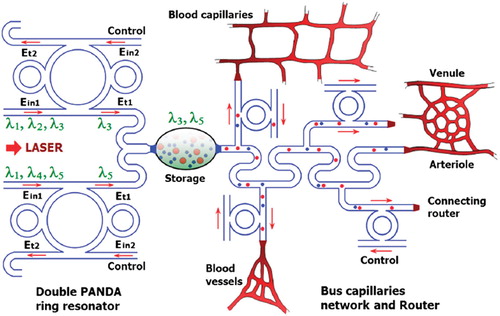
In this study, the dynamic optical tweezers/vortices are generated using a dark soliton, bright soliton, and Gaussian pulse propagating within an add/drop optical multiplexer incorporating two nanoring resonators (PANDA ring resonator). The dynamic behaviors of soliton and Gaussian pulses are well described in reference [Citation29]. By using the proposed system, the transceiver can be integrated and performed by using a single device. Here, the use of two different wavelength tweezers, molecular buffers, and bus networks to form the drug volume transportation, especially for large drug volume delivery and transportation, is described, which can be available for a multi-drug delivery network, molecular diagnostic networks, blood circulation networks, Alzheimer's and Parkinson's diagnosis, and molecular electronics, which will be discussed in current and future developments. In addition, when two different wavelength tweezers are fed into the network, we found that molecular network stability is confirmed. In application, the multi drug delivery networks can perform for large-scale drug delivery applications.
PRINCIPLES AND METHOD
In theory, the trapping forces are exerted by the intensity gradients in the strongly focused beams of light to trap and move the microscopic volumes of matters, in which the optical forces are customarily defined by the relationship [Citation30]
Here Q is a dimensionless efficiency, nm is the index of refraction of the suspending medium, c is the speed of light, and P is the incident laser power, measured at the specimen. Q represents the fraction of power utilized to exert force. For plane wave incident on a perfectly absorbing particle, Q is equal to 1. To achieve stable trapping, the radiation pressure must create a stable, three-dimensional equilibrium. Because biological specimens are usually contained in aqueous medium, the dependence of F on nm can rarely be exploited to achieve higher trapping forces. Increasing the laser power is possible, but only over a limited range due to the possibility of optical damage. Q itself is therefore the main determinant of trapping force. It depends upon the NA (numerical aperture), laser wavelength, light polarization state, laser mode structure, relative index of refraction, and geometry of the particle.
Furthermore, in the Rayleigh regime, the trapping forces decompose naturally into two components. Since, in this limit, the electromagnetic field is uniform across the dielectric, particles can be treated as induced point dipoles. The scattering force is given by
Here
Here σ is the scattering cross-section of a Rayleigh sphere with radius r. 〈S〉 is the time averaged Poynting vector, n is the index of refraction of the particle, m = n/nm is the relative index, and k = 2πnm /λ is the wave number of the light. The scattering force is proportional to the energy flux and points along the direction of propagation of the incident light. The gradient field (Fgrad) is the Lorentz force acting on the dipole induced by the light field. It is given by [Citation30]
Where
is the polarizability of the particle. The gradient force is proportional and parallel to the gradient in energy density (for m > 1). The large gradient force is formed by the large depth of the laser beam, in which the stable trapping requires that the gradient force in the 2z direction, which is against the direction of incident light (dark soliton valley), is greater than the scattering force. By increasing the NA, when the focal spot size is decreased the gradient strength is increased [Citation31], which can be formed within a tiny system; for instance, nanoscale device (nanoring resonator).
In our proposal, the trapping force is formed by using a dark soliton, in which the valley of the dark soliton is generated and controlled within the PANDA ring resonator by the control port signals. From , the output field (Et1) at the through port is given by [Citation30]
Figure 1. Schematic diagram of a buffer and bus networks: (a) a PANDA ring resonator; (b) a wavelength router and bus networks, where Radd is the add/drop filter radius, RR and RL are the right and left ring resonator radii, respectively.
Et and Ed represent the optical fields of the through port and drop ports, respectively. β = kneff is the propagation constant, neff is the effective refractive index of the waveguide, and the circumference of the ring is L = 2πR, where R is the radius of the ring. κ1 and κ2 are the coupling coefficients of the add/drop filters, kn = 2π/λ is the wave propagation number in a vacuum, and the waveguide (ring resonator) loss is α = 0.5 dBmm − 1. The fractional coupler intensity loss is γ = 0.1. In the case of the add/drop device, the nonlinear refractive index is not effect to the system; therefore it is neglected. The electric fields E0 and E0L are the field circulated within the nanoring at the right and left side of add/drop optical filter.
The power output (Pt1) at through port is written as
The output field (Et2) at drop port is expressed as [Citation30]
where
The power output (Pt2) at drop port is
MOLECULAR NETWORK
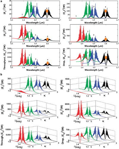
The molecular buffer is a device that can be used to store or delay atoms/molecules for a period of time (see ), where light intensity and velocity can also be controlled, which was described by the authors in references [Citation32,Citation33], and is available for medical application. The molecular buffer is a new device that is operated in the same way as a gas buffer [Citation34]. The polarizability of the particle is calculated using Equation (5), where in this case we assume that the sphere particle is polystyrene (n = 1.5894) and the liquid medium is water (n = 1.33), and the optical power (which is required to trap particles of a certain size/polarizability) is 9.1 W, which is the slope of graph as shown in . In simulation, the bright soliton with center wavelength at 1.50 µm, peak power 2W, pulse width of 35fs is input into the system via the input port, where the coupling coefficients are given as κ0 = 0.5, κ1 = 0.35, κ2 = 0.1 and κ3 = 0.35, respectively. The ring radii are Radd = 20 µm, RR = RL = 5 µm, respectively. The evidence of the practical device with the radius of 2–3 µm has been reported by the authors in reference [Citation23]. Aeff are 200 μm2: In this case, the dynamic tweezers (gradient fields) can be in the forms of bright solitons, Gaussian pulses, and dark solitons, which can be used to trap the required microscopic volume. There are four different center wavelengths of tweezers generated, in which the dynamical movements are seen in , with (a) different sizes and wavelengths tweezers, and (b) tunable tweezers by coupling constant variation, where the required drug volumes can be obtained by the drop port outputs.
Figure 2. Schematic of molecular buffer work in core waveguide.
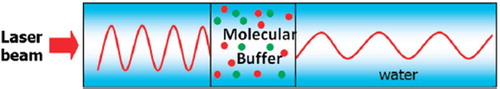
Figure 3. Graph of optical power that is required to trap the particle of a certain size/polarizibility.
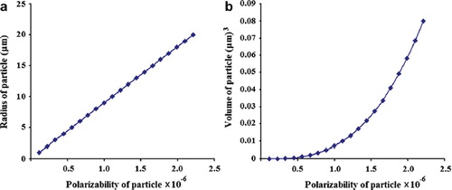
Figure 4. Result of the dynamic tweezers with different (a) wavelengths and (b) tunable tweezer by coupling constants, where Radd = 20 μm, RR = RL = 5 μm.
In practice, the fabrication parameters that can be easily controlled are the ring resonator radii instead of coupling constants. The important aspect of the result is that the tunable tweezers can be obtained by tuning (controlling) the add (control) port input signal, in which the required number of microscopic volume (atom/photon/molecule) can be obtained and seen at the drop/through ports; otherwise, they propagate within a PANDA ring before collapsing/ decaying into the waveguide. In application, the trapped drug molecules can transport into the wavelength router via the through port, while the retrieved drug volumes are received via the drop port (connecting target). The advantage of the proposed system is that the transmitter and receiver can be fabricated on-chip and alternatively operated by a single device. The magnitude of optical trapping force is in the pico Newton (pN), which depends upon the relative refractive index of particle, which was given by the authors in reference [Citation35]. The particle radius was given by the authors in references [Citation36,Citation37], and is located in the cavity. It decreases with the decrease in refractive indices compared to the host medium.
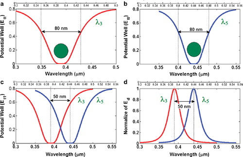
The waveguide of the drug delivery system can be an optical waveguide with a liquid core which is allowed to trap drug molecules smoothly within the network. By using the drug bus network, the trapped drug molecules can be transported to the required drug targets and delivery, in which the specific drug molecules can be obtained by using the molecular transceiver. To form the trapping tools, the PANDA ring resonator has 4 ports as shown in . First, the dark-soliton is fed into the system via the input port. Second, output trapping tools transmit into the throughput port and bus networks. Third, the required drug molecules are filtered and obtained via the drop ports. Finally, there are some molecules transported within the bus networks and drug routers, in which the control port is available for additional applications. In , the molecular trapping probe can be adjusted to fit the drug molecule size from 10 nm to 15 nm, which can be used for drug molecule transportation at the through port and networks. The number of molecules can be increased within the PANDA ring resonator, as shown in (a). In addition, the trapping tool (probe) or dynamic well size can be adjusted by varying the coupling coefficient of PANDA microring as shown in (b), where the other parameters are given in the Figure captions.
Figure 5. Results of the trapping tools: (a) and (b) different sizes and wavelengths; (c) tweezers separation; (d) normalized tweezers, where Radd = 20 µm, RR = RL = 5 µm. The coupling coefficients are κ0 = 0.5, κ1 = 0.35, κ2 = 0.1 and κ3 = 0. 35. The input power is 1W, Radd = 20 µm, RL = Rr = 5 µm: (a) wavelength = 400 nm; (b) wavelength = 450 nm; (c) wavelengths = 400, 450 nm; (d) wavelengths = 400, 600 nm.
NETWORK STABILITY
Several works have shown that the use of fluidics particles (drug volumes) can perform realistic applications [Citation38,Citation39]. In this paper, the proposed system has shown that a tiny device in the form of thin film can be fabricated and used [Citation40], in which the integrated system of the drug network can be inserted into the application area, where the feasibility applications such as drug delivery network for large area diagnosis can be available, as shown in . Moreover, the use of the proposed system for an artificial bone and blood circulation network is also available, in which the use for in situ surgery or operation, neural and brain diagnosis is also plausible.
Figure 6. Schematic diagram of molecular bus network.
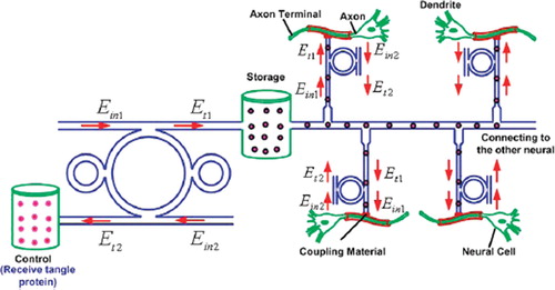
By using the design networks, the required trapped volumes can be transported within the network via the molecular buffer(storage) into the required destinations; for instance, the trapped tangle protein can be filtered via the add/drop filter before reaching the desired destinations. The throughput port (Et1) output of add/drop filter is connected to the axon (axon terminal), then to the neural cell and dendrite. The effective area of the waveguide is 2.01 mm2 (r = 800 nm) and the outside diameter of the microtubule is 25 nm [Citation41]. The size of the axons’ diameter at birth is 1 m; it increases through childhood (7 years) to 12 m and later to 24 m at adulthood [Citation42]. In the case of Alzheimer's diagnosis, as reported by the authors in reference [Citation43], the optical tool connects the axon and the nerve cells, which can be used to trap the tangle protein into the removal storage by the add/drop filter (control port); otherwise, the bus network as design can be used to trap the molecular motor to activate the information of the neuronal cell at the same time. For better access, the coupling material is required to be used as waveguide-axon coupling.
In operation, because “networks” are made up of add/drop filters as shown in , the performance depends on that of add/drop filters. Recently, the micro and nano waveguides are gaining prominence. Filters offer good stability and isolation between channels at moderate cost. For one thing, add/drop filters’ capability will impact the size of the network. The maximum nodes of a network depend on the maximum amount of channels of the add/drop filter. The popular dense wavelength division multiplexing (DWDM) component with many channels has been achieved in both laboratory and theoretical works [Citation44,Citation45]. That means it is possible to build a “multi variable routers or networks” with many ports in the future.
In this work, we propose to use the optical network principle for network stability calculation, but in this case the system is reduced to reach the microscale dimension, where in general the problems of a large network which reduce network stability are insertion loss (IL) and crosstalk effect (FC). First, the insertion loss will reduce the efficient transmission distance. Normally, in the popular communication network, the signals will pass through the “router,” and the insertion loss of popular device is 5 dB. According to the performance of the present point-to-point transmission system, we can build a required network over 50 km at least. That will still meet the requirement of a big city. Along with the development of DWDM technology, the insertion loss will be less than 1 dB in future [Citation46], and then the multivariable network will cover more than 100 km with high capacity. Second, the crosstalk effect is mainly due to a signal of co-channel interference and adjacent-channel interference. The crosstalk will be considered in terms of channel separability. For a network, crosstalk will bring bit errors, so it must be reduced as low as possible. We think it can be estimated as follows: The insertion loss (IL) and crosstalk (FC) is:
Here Pin and Pout are input and output of soliton, Pj(li) is output of soliton with wavelength li which exports from port j, Pi(li) is output of soliton with wavelength li which exports from port i. Pi(li) in Equation (11) is equal to Pout in equation (10).
We first assume that all input of photons from any user is the same when they enter the “router,” since one soliton passes through two add/drop filters when it pass a “router,” crosstalk versus efficient signals is:
Now we consider the situation that the input soliton is not the same. A terrible situation is that input photons which produce efficient signals pass through a device that has X dB insertion loss before passing through a “router,” but those solitons which produce crosstalk do not. The ratio in Equation (14) will become 10[X + 2 × FCj(li)]/10. If there are many inputs that produce crosstalk, the ratio must be
Here j ≠ i, where N is the amount of channels (receiver nodes).
In this case study, the system dimension is reduced to the micro/nanoscale, from , where in this case the coupling ratio of each coupling point is 50:50, i.e. 3 dB coupling power. The molecular bus network has N = 4, FCj(li) < −4.26 dB (when j = i ± 1), X = 20.97dB. In this case, the normalized input is 0.8; li and lj equal 400 and 450 nm, respectively. The ratio is less than 0.113%. Therefore the errors brought by crosstalk are less than other effects and can be ignored. Along with the development of DWDM technology, crosstalk is smaller and the performance of a “molecular router or network” can be improved; in this case, we can easily build a feasible multi variable network for multi drug delivery applications, i.e. for large networks.
CONCLUSIONS
We have proposed an interesting system that can be used to perform multi drug delivery networks, in which the trapped drug molecules can move into the liquid core waveguide and networks by using optical tweezers, where the drug trapping, storage, and delivery via the molecular network can be realized. Moreover, such a system can also be available for a large-scale molecular drug delivery network and diagnosis. The network stability was also calculated, in which we found that the crosstalk effects due to the two wavelength trapping drug molecules can be neglected. In conclusion, we have shown that the use of multi drug delivery networks to form long-distance drug molecule transportation is realized by using the proposed system, in which the drug delivery or molecular communication can be performed via the wavelength router and bus network, which can be available for a large network system (neural system) in the near future. Furthermore, the proposed technique can be used for the new era of electronics and communications, where the use of molecules, DNA, genes, and atoms can form various applications within the tiny system, which we will continue to research.
Declaration of interest: The authors report no conflicts of interest. The authors alone are responsible for the content and writing of the paper.
REFERENCES
- Mason, O., Verwoerd, M. (2007). Graph theory and networks in biology. IET Systems Biology, 1(2): 89–119.
- Corni, S. (2007). A theoretical study of the electrochemical gate effect in an STM-based biomolecular transistor. IEEE Transaction on Nanotechnology, 6(5): 561–570.
- Gregori, M., and Akyldiz, I.F. (2010). A new nanonetwork architecture using flagellated bacteria and catalytic nanomotors. IEEE J. Selected Areas in Communications, 28(4): 612–619.
- Chen, Y.P., Chen, F. (2008). Identifying targets for drug discovery using bioinformatics. Expert. Opin. Ther. Targets., 12(4): 383–389.
- Makowski, M.S., Ivanisevic, A. (2011). Molecular analysis of blood with micro-/nanoscale field-effect-transistor biosensors. Small, June 3, doi: 10.1002/smll. 201100211.
- Schweiger, R., Linial, M., Linial, N. (2011). Generative probabilistic models for protein–protein interaction networks—the biclique perspective. Bioinformatics., 27(13): doi:10.1093.
- Taengtang, T., Praitoonwattanakit, K., and Yupapin, P.P. (2010). Molecular network based on ant colony system via wavelength router. Microw. Opt. Thechnol., 52(9): 2139–2142.
- Wang, Y.C., Chen, B.S. (2011). A network-based biomarker approach for molecular investigation and diagnosis of lung cancer. BMC Med. Genomics., 4(2): doi: 10.1186/1755-8794-4-2.
- Gin, L.P., Akyildiz, I.F. (2009). Molecular communication options for long range nanonetworks. Computer Networks., 53: 2753–2766.
- Suwanpayak, N., Jalil, M.A., Aziz, M.S., Ali, J., Yupapin, P.P. (2011). Molecular buffer using a PANDA ring resonator for drug delivery use. Int J Nanomed., 6: 575–580.
- Suwanpayak, N., Jalil, M.A., Aziz, M.S., Ismail, F.D., Ali, J., Yupapin, P.P. (2011). Blood cleaner on-chip design for artificial human kidney manipulation. Int J Nanomed., 6: 957–964.
- Suwanpayak, N., Jalil, M.A., Teeka, T., Ali, J., Yupapin, P.P. (2011) Optical vortices generated by a PANDA ring resonator for drug trapping and delivery applications. Bio. Med. Opt. Express, 2(1): 159–168.
- Ashkin, A., Dziedzic, J.M., Yamane, T. (1986). Observation of a single-beam gradient force optical trap for dielectric. Opt. Lett., 11: 288–290.
- Chen, H.D., Ge, K., Li, Y., Jianguang, W.J., Gu, Y., Haiming, W.H., Tian, Z. (2007). Application of optical tweezers in the research of molecular interaction between lymphocyte function associated antigen-1 and its monoclonal antibody. Cell Mol. Immunol., 4: 221–225.
- Lee, W.G., Park, K., Bang, H., Chung, S., Chung, C., Han, D.C. (2005). Single red blood cell defromnility test using optical trapping in plastic microfluid chip. Proceedings of the 31 Annual International IEEE EMBS Special Topic on Conference Microtechnologies in Medicine and Biology Kahuku, Oahu, Hawaii, 12–15 May 2005, 389–90.
- Obrist, D., Weber, B., Buck, A., Jenny, P. (2010). Red blood cell distribution in simplified capillary. Phil. Trans. R. Soc., 368: 2897–2918.
- Chen, Y.C., Chen, G.Y., Lin, Y.C., Wang, G.J. (2010). A lab-on-a-chip capillary network for red blood cell hydrodynamics. Microfluid Nanofluid., 9: 585–91.
- Cheng, M., Wu, C., Hiltunen, J., Wang, Y., Wang, Q., Myllylä, R. (2009). A variable delay optical buffer based on nonlinear polarization rotation in semiconductor optical amplifier. IEEE. Photon. Technol. Lett., 21: 1885–1887.
- Liu, J., Lee, T.T., Jiang, X., Horiguchi, S. (2009). Blocking and delay analysis of single wavelength optical buffer with general packet size distribution. J. Lightwave. Technol., 27: 955–966.
- Dragone, C.P. (2010). Improved waveguide grating optical router suitable for CWDM. EP2250523.
- Ham, B.S. (2010). Delayed optical router/switch. US20100232792.
- Oguchi, K., Terada, S. (2010). Optical network system, optical router, fault recovery method of optical network, and program. JP2010063009.
- Piyatamrong, B., Kulsirirat, K., Mitatha, S., Yupapin, P.P. (2010). Dynamic potential well generation and control using double resonators incorporating in an add/drop filter. Mod. Phys. Lett. B, 24: 3071–3082.
- Cai, H., Poon, A. (2010). Optical manipulation and transport of microparticle on silicon nitride microring resonator-based add-drop devices. Opt. Lett., 35: 2855–2857.
- Ashkin, A., Dziedzic, J.M., Bjorkholm, J.E., Chu, S. (1986). Observation of a single-beam gradient force optical trap for dielectric particles. Opt. Lett., 11: 288–290.
- Egashira, K., Terasaki, A., Kondow, T. (1998). Photon-trap spectroscopy applied to molecules adsorbed on a solid surface: Probing with a standing wave versus a propagating wave. App. Opt., 80: 5113–5115.
- Kachynski, A.V., Kuzmin, A.N., Pudavar, H.E., Kaputa, D.S., Cartwright, A.N., Prasad, P.N. (2003). Measurement of optical trapping forces by use of the two-photon-excited fluorescence of microspheres. Opt. Lett., 28: 2288–2290.
- Schulz, M., Crepaz, H., Schmidt-Kaler, F., Eschner, J., Blatt, R. (2007). Transfer of trapped atoms between two optical tweezer potentials. J. Mod. Opt., 54: 1619–1626.
- Tasakorn, M., Teeka, C., Jomtarak, R., Yupapin, P.P. (2010). Multitweezers generation control within a nanoring resonator system. Opt. Eng., 49: 075002.
- Svoboda, K., Block, S.M. (1994). Biological applications of optical forces. Ann. Rev. Biophy. Biomol. Struct., 23: 247–282.
- Rosenberry, M.A., Reyes, J.P., Tupa, D., Gay, T.J. (2007). Radiation trapping in rubidium optical pumping at low buffer-gas pressures. Phys. Rev. A, 75: 023401 -1–6.
- Lignie, M.C., Woerdman, J.P. (1990). Light-induced drift of Na in molecular buffer gases. J. Phy. B: At Mo. Opt. Phys., 23: 417–426.
- Waggoner, P.S., Palmer, J.S., Antonov, V.N., Weaver, J.H. (2005). Metal nanostructure growth on molecular buffer layers of CO2. Surface Sci., 596: 12–20.
- Zhu, J., Ozdemir, S.K., Xiao, Y.F., Li, L., He, L., Chen, D.R. . (2010). On-chip single nanoparticle detection and sizing by mode splitting in an ultrahigh-Q microresonator. Nat. Photon., 4: 46–49.
- Fischer, M., Sørensen, K.B. (2007). Calibration of trapping force and response function of optical tweezers in viscoelastic. J. Opt. A, Pure. App. Opt., 79: 239–250.
- Nieminen, T.A., Dunlop, H.R., Heckenberg, N.R. (2001). Calculation and optical measurement of laser trapping forces on non-spherical particles. J. Quantitative Spectro. & Rad. Trans., 70: 627–637.
- Segev, M., Christodoulides, D.N., Rotschild, C. (2011). Method and system for manipulating fluid medium. US 2011/0023973 A.
- Bugge, M., Palmers, G. (2010). Implantable device for utilization of the hydraulic energy of the heart. US RE41, 394 E.
- Chen, S.Y., Hu, S.H., Liu, D.M., Kuo, K.T. (2011). Drug delivery nanodevice, its preparation method and used thereof. US 2011/0014296 A1 (patent).
- Macleod, H.A. (2010). Thin-Film Optical Filter, 4th ed. New York: Taylor & Francis.
- Karp, G.. (2010). Cell and Molecular Biology, 6th ed. New York: John Wiley & Sons.
- Paus, T., Toro, R. (2009). Could sex differences in white matter be explained by g ratio? Neuro., 3(14): 1–7.
- Mitatha, S., Moongfangklang, N., Jalil, M.A., Suwanpayak, N., Saktioto, T., Ali, J., Yupapin, P.P. (2011). Proposal for Alzheimer's diagnosis using molecular buffer and bus network. Int J Nanomed., 6: 1209–1216.
- Takada, K., Abe, M., Shibata, T., Okamoto, K. (2002). Field demonstration of over 1000-channel DWDM transmission with supercontinuum multi-carrier source. Electron. Lett., 38: 572–573.
- Sarapat, K., Ali, J., Yupapin, P.P. (2009). A novel storage and tunable light source generated by a soliton pulse in a micro ring resonator system for super dense wavelength division multiplexing use. Microw. Opt. Technol. Lett., 51: 2948–2952.
- Smit, M.K. (2005). Progress in AWG design and technology. In: Proceedings of WFOP, 4th IEEE/LEOS workshop on fibers and optical passive component, p. 26.