Abstract
This paper presents the use of a modified add/drop optical filter incorporating with microring resonators known as a PANDA microring resonator system which can fabricate on small chip. By using an optical tweezer, the required molecules can be trapped and moved to the required destinations at the add/drop ports. The novelty is that the stored molecules in the designed chip can transport via the optical waveguide and can also be used to form molecular filter, which is an important technique for drug delivery, drug targeting, and molecular electronics. Results have shown that the multivariable filter can be obtained by tunable trapping control.
Introduction
A PANDA ring resonator is used to trap, transmit, and transport volume of drug to desired destination by controlling the ring parameters. A microscopic volume is trapped and moved dynamically within the wavelength router or network. The theoretical and experimental investigations have been reported to trap and transport a microscopic volume within the add/drop multiplexer using optical tweezers. For the manipulation of micrometer-sized particles, the optical tweezer generation technique has become a powerful tool (Jalil et al. Citation2011). By providing and controlling the suitable input power signals in the system, the dynamic optical tweezers can be generated, tuned, and stored within the ring resonator system before reaching the desired destinations via an optical waveguide. The PANDA microring device is used in many applications such as to trap, store, and deliver the tangle protein for Alzheimer's diagnosis (Jalil et al. Citation2012), gold nanoparticles for cosmetic therapy (Aziz et al. Citation2011), as buffer to form a nanomicro syringe system for drug delivery (Jalil et al. Citation2011) molecular filter (Chen et al. Citation2003), drug delivery (Gareth Citation2005, Verma and Garg Citation2001, Peppas and Mongia Citation1997, Langer and Peppas Citation2003, Peppas and Byrne Citation2003, Langer Citation1998, Goyal et al. Citation2005, Everard et al. Citation1992, Nakamura et al. Citation2001, Verma et al. Citation2000) hybrid transistor (Suwanpayak et al. Citation2011c), therapeutic (Aziz et al. Citation2011) It is also used for blood waste trapping and moves dynamically within the blood cleaner on-chip system (artificial kidney), and the blood quality test is exploited by the external probe before sending to the destination (Suwanpayak et al. Citation2011a). Optical microresonators have attracted attention in the photonics community as they have applications ranging from quantum electrodynamics to sensors and filtering devices for optical telecommunication systems, where they serve as an essential building block (Guarino et al. Citation2007). Electro-optic (EO) ring resonator has a number of applications in telecommunication and scientific fields, such as optical signal processing (OSP), analog optical links, and frequency comb generation. The optical ring modulators show superior performance compared to the existing low-frequency modulator (Bortnik et al. Citation2007). Optical microring resonators are an emerging bio/chemical sensing technologies which are under intensive investigation (Fan et al. Citation2007). In this proposed work, the simulation results are obtained using the commercial MATLAB software, realized by the multivariable molecular filter within the micro/nanoscale networks, which is useful for drug delivery applications.
Molecule trapping principle
A novel designed PANDA microring resonator was proposed by the authors (Tasakorn et al. Citation2010a). A PANDA ring is a modified optical add/drop filter that can be applied to many applications by changing the structure of PANDA and signals, in which the major behaviors are the two nonlinear side rings. The superposition of the different input signals can bring different output signals, which can be used for many applications. Therefore, the PANDA theory is the same to the previous works but the structure and signals are different. This paper uses the PANDA theory for trapped electron that moves in the embedded device via the optical waveguide to the metal contact. Electron can move to the metal contact without recombination center in the silicon bulk; therefore, the electron speed is increased, because the recombination lifetime decreases. In this work, the simulation parameters of the proposed material are chosen closely to the practical fabricated device. By using a dark–bright soliton pulses as input propagate within a modified add/drop optical multiplexer (PANDA microring), it acts as trapping tool to trap molecules/atoms. In this work, the multiplexed signals with slightly different wavelengths of the dark solitons are controlled and amplified within the system. The dynamic behaviors of dark–bright soliton interaction are analyzed and described. Finally, optical switching is used to form a solar cells using the Gaussian control at the add port. In practice a Gaussian pulse can be obtained from a simple laser source, where a soliton pulse can be obtained by a fiber laser source. In application, both laser pulses can be used to form the optical tweezer but the differences are the system performance and cost.
A stationary dark soliton pulse is introduced into the add/drop optical filter and the input optical field (Ein) and the add port optical field (Eadd) of the dark–bright soliton or Gaussian pulses are given by
Here A and x are the optical field amplitude and propagation distance, respectively. T is a soliton pulse propagation time in a frame moving at the group velocity, T = t‐β1x, where β1 and β2 are the coefficients of the linear and second-order terms of Taylor expansion of the propagation constant. LD = (R0)2/ǀβ2|, which is the dispersion length of the silicon pulse. T0 in equation is a soliton pulse propagation time at initial input (or soliton pulse width), where t is the soliton phase shift time, and the frequency shift of the soliton is ω0. This relationship describes a pulse that keeps its temporal width invariance as it propagates, and thus is called a temporal soliton. When a soliton of peak intensity ǀβ2/G(T0)2| is given, then T0 is known. For the soliton pulse in the microring device, a balance should be achieved between the dispersion length (LD) and the nonlinear length (LNL = 1/ГϕNL). Here Г = n2k2 is the length scale over which dispersive or nonlinear effects make the beam wider or narrower. For a soliton pulse, there is a balance between dispersion and a nonlinear length. Hence LD=LNL. For Gaussian pulse in Eq. (1c), E0 is the amplitude of optical field.
When light propagate within the nonlinear medium, the refractive index (n) of light within the medium is given by
where n0 and n2 are the linear and nonlinear refractive indexes, respectively. I and P are the optical intensity and the power, respectively. The effective mode core area of the device is given by Aeff. For the add/drop optical filter design, the effective mode core areas range from 0.50 to 0.10 μm2, in which the parameters are calculated by the related practical material parameters (InGaAsP/InP). When a dark soliton pulse is input and propagate within add/drop optical filter as shown in , the resonant output is formed.
Figure 1. A PANDA microring resonator.
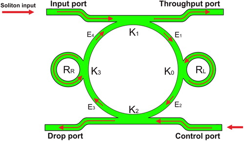
The resonator output field, Et1 and E1 consists of the transmitted and circulated components within the add/drop optical filter system, which generates a force to drive photon/molecule/atom. For the first coupler of the add/drop optical filter system, the transmitted and circulated components can be written as
Here k1 is the intensity coupling coefficient, γ1 is the fractional coupler intensity loss, α is the attenuation coefficient, kn = 2π/λ is the wave propagation number, λ is the input wavelength light field, and L = 2πRad, Rad is the radius of add/drop device.
For the second coupler of the add/drop system,
Here k2 is the intensity coupling coefficient, γ2 is the fractional coupler intensity loss. E0 and E0L are the circulated light fields components of the nanoring radii, Rr and RL coupled to the right and left sides of the add/drop optical filter system, respectively. The light field transmitted and circulated components in the right nanoring, Rr, are given by
Similarly, the output optical field of the drop port (Et2) is given by
The power output of the drop port (Pt2) is expressed by
Molecular filter manipulation
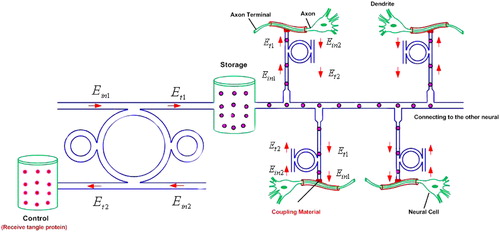
In the proposed design, the optical waveguide can be used to trap molecules/atoms (Suwanpayak et al. Citation2011b, Youplao et al. Citation2010, Tasakorn et al. Citation2010b) with molecular filter constructed incorporating with the optical tweezer assembly, in which the trapped molecules can transfer to the device via the optical waveguide as shown in . In simulation, the input signal is a bright soliton and Gaussian pulses at the peak power of 100 mW. The ring parameters are RR = RL = 5 μm and the add/drop Rad = 20 μm. The coupling coefficients of the PANDA ring resonator are set to κ = κ1 = κ2 = κ3 = 0.5. The effective core areas (Aeff) are 300 μm2.
Figure 2. Schematic diagram of molecular filter, where (a) an embedded PANDA microring resonator, (b) molecule movement along the waveguide via a through port.
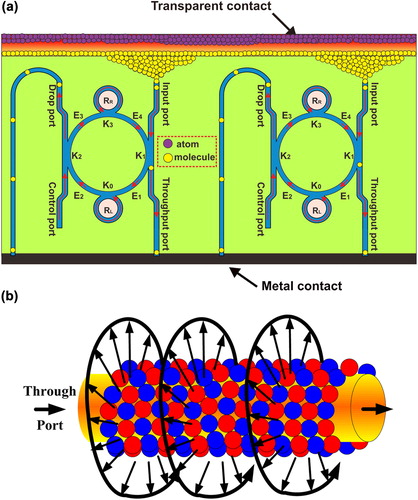
The waveguide loss coefficient (α) is 0.1 and coupling loss (γ) is 0.01 and the refractive index (n0) is 1.37. The dimensions of optical tweezers are controlled by various tweezer sizes and kappa (κ) fit for particle size. shows the optical tweezers with different positions (E1, E2, E3, and E4) that are generated by the PANDA ring, where Et1 and Et2 are the throughput and drop ports, respectively. In this figure, the results of different center wavelength tweezers are red = 1.4 μm, green = 1.45 μm, blue = 1.5 μm, and black = 1.6 μm, where the shape and peak power of the fields are different for each center wavelengths. The highest peak signal of optical tweezers is at wavelength of 1.4 μm. The trapping tool size (d) is required to tune between these two conditions, (i) d > molecule size and (ii) d < molecule size. Therefore, the trap size is required to fit the molecule size (0.22 nm) (Wernert et al. Citation2010). We can filter many particle sizes by control kappa parameter as shown in , where the optical tweezers can be chosen according to the molecule size for trapping via the optical waveguide. In practice, the optical tweezers (light signals) can propagate within the optical waveguide, which means that the trapped molecules can transport to the required destinations via the surface based on the gradient potential (force) and surface plasmon behaviors. Therefore, by using the proposed system, molecules can be trapped and transported via the suitable waveguide to the required targets with some specific molecule sizes, in which the molecular filter concept is established. shows drug molecules using PANDA ring resonator system which are trapped within the generated tweezers and transported to required destination via network. The required molecules (drug) molecule sizes and types are selected, controlled, and filtered using the proposed filter device. The molecular filters can be used to form the molecular networks, in which each of molecular filters can be linked and accessed to the target cells. For instance, the tangle protein can be trapped, stored, and transported from a bottle (storage tank) to the nerve cells or dendrites (axon or axon terminal) via the molecular network. In operation, the molecular network can be fabricated by using the filter materials (silicon and InGaAsP/InP), in which molecules can move along the waveguide (b) due to the dragging force introduced by the gradient fields (Ashkin et al. Citation1986, Cai and Poon Citation2010) where, finally, the required molecules can be retrieved by molecular filtering control application. In this case, the networks can be formed within a millimeter to centimeter scale.
Figure 3. Results of dynamic optical tweezers generated at four different center wavelengths, where (a) |E1ǀ2, (b) |E2ǀ2, (c) ǀE3|2, (d) ǀE4ǀ2, (e) through, and (f) drop port signals.
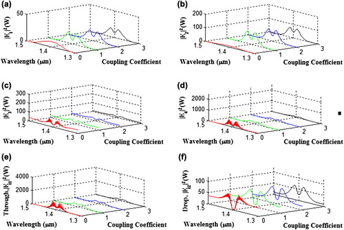
Figure 4. (a) An optical tweezer and trapped electron generated by a PANDA microring resonator, (b) results of the trapping potential well with various coupling coefficients (kappa, κ).
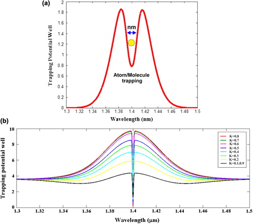
Figure 5. Drug filter in the targeting network.
Conclusion
We have proposed an interesting technique, which can be a good candidate for drug delivery or molecular electronics use. By using optical tweezers generated by an embedded modified optical filter, molecules can be trapped and transported via the optical waveguide to the required destination through device. The dynamic behaviors of optical tweezers are generated and controlled by using PANDA microring resonator parameters. This technique can be also used to form the multivariable molecular filter within the micro/nanoscale networks. From the obtained simulation results, it is found that this technique has potential to act as molecular filter. Furthermore, this technique can also be used to improve the device such as molecular capacitor, transistor, and other molecular devices.
Acknowledgements
We would like to thank the Institute of Advanced Photonics Science, Nanotechnology Research Alliance, Universiti Teknologi Malaysia (UTM), and King Mongkut's Institute of Technology (KMITL), Thailand for providing research facilities.
Declaration of interest
The authors report no conflicts of interest. The authors alone are responsible for the content and writing of the paper.
This research work has been supported by UTM's Tier 1/Flagship Research Grant, MyBrain15 Fellowship/MOHE SLAI Fellowship, and the Ministry of Higher Education (MOHE) research grant.
References
- Ashkin A, Dziedzic JM, Bjorkholm JE, Chu S. 1986. Observation of a single-beam gradient force optical trap for dielectric particles. Optic Lett. 11:288–290.
- Aziz MS, Suwanpayak N, Jalil MA, Jomtarak R, Saktioto T, Ali J, Yupapin PP. 2011. Gold nanoparticle trapping and delivery for therapeutic applications. Int J Nanomed. 7:11–17.
- Bortnik B, Hung YC, Tazawa H, Seo BJ, Luo J, Jen AKY, et al. 2007. Electrooptic polymer ring resonator modulation up to 165 GHz. IEEE J Sel Top Quant Electron. 13:104–110.
- Cai H, Poon A. 2010. Optical manipulation and transport of microparticle on silicon nitride microring resonator-based add-drop devices. Optic Lett. 35:2855–2857.
- Chen J, Lee T, Su J, Wang W, Reed MA. 2003. Molecular Electronics Device. New York: American Scientific Publishers.
- Everard ML, Clark AR, Milner AD. 1992. Drug delivery from jet nebulisers. Arch Dis Child. 67:568–591.
- Fan X, White IM, Zhu H, Suter JD, Oveys H. 2007. Overview of novel integrated optical ring resonator bio/chemical sensors. Proc SPIE. 6452, 6452M.
- Gareth AH. 2005. Nanostructure-mediated drug delivery. Nanomedicine Nanotechnol Biology Medicine. 1:22–30.
- Goyal R, Goyal K, Kumar SGV, Singh A, Katare OP, Mishra DN. 2005. Liposomal drug delivery systems-clinical application. Acta Pharm. 55:1–25.
- Guarino A, Poberaj G, Rezzonico D, Degl’Innocenti R, Gunter P. 2007. Electro–optically tunable microring resonators in lithium niobate. Nat Photon. 1:407–410.
- Jalil MA, Kamoldilok S, Saktioto T, Ong CT, Yupapin PP. 2012. Drug trapping and delivery for Alzheimer's diagnosis. Artif Cell Blood Substit Biotechnol. PMID:22384850.
- Jalil MA, Suwanpayak N, Kulsirirat K, Suttirak S, Ali J, Yupapin PP. 2011. Embedded nano-syringe on chip for Molecular therapy. Int J Nanomed. 6:2925–2932.
- Langer R, Peppas NA. 2003. Advance in biomaterials, drug delivery, and bionanotechnology. AIChE I. 49:2990–3006.
- Langer R. 1998. Drug delivery and targeting. Nature. 392:5–10.
- Nakamura O, Lowe RD, Mitchem L, Snook RD. 2001. Diffusion of nitroglycerin from drug delivery parches through micro-fiber filters using Fourier transform infrared photoacoustic spectrometry. Anal Chim Acta. 427:63–73.
- Peppas NA, Byrne ME. 2003. New biomaterials for intelligent biosensing, recognitive drug delivery and therapeutics. Bull Gattefosse. 96:23.
- Peppas NA, Mongia NK. 1997. Ultrapure poly (vinyl alcohol) hydrogels with mucoadhesive drug delivery characteristics. Eur I Pharm Biopharm. 43:51–58.
- Suwanpayak N, Jalil MA, Aziz MS, Ismail FD, Ali J, Yupapin PP. 2011a. Blood cleaner on-chip design for artificial human kidney manipulation. Int J Nanomed. 6:975–964.
- Suwanpayak N, Jalil MA, Teeka C, Ali J, Yupapin PP. 2011b. Optical vortices generated by a PANDA ring resonator for drug trapping and delivery applications. Biomed Opt Express. 2:159–168.
- Suwanpayak N, Teeka C, Yupapin PP. 2011c. Hybrid transistor manipulation controlled by light. Microw Opt Tech Lett. 53: 2533–2537.
- Tasakorn M, Teeka C, Jomtarak R, Yupapin PP. 2010a. Multitweezers generation control within a nanoring resonator system. Opt Eng. 49:075002.
- Tasakorn M, Teeka C, Jomtarak R, Yupapin PP. 2010b. Multitweezers generation control within a nanoring resonator system. Opt Eng. 49:075002-1-7.
- Verma RK, Garg S. 2001. Current status of drug delivery technologies and future directions. Pharmaceyt Technol. 25:1–14.
- Verma RK, Mishra B, Garg S. 2000. Osmotically controller oral drug delivery. Drug Dev Ind Pharm. 26:695–708.
- Wernert V, Bouchet R, Denoyel R. 2010. Influence of molecule size on its transport properties through a porous medium. Anal Chem. 82:2668–2679.
- Youplao P, Phattaraworamet T, Mitatha S, Teeka C, Yupapin PP. 2010. Novel optical trapping tool generation and storage controlled by light. J Nonlinear Opt Phys Mater. 19:371–378.