Abstract
This study presents a clinical validation of postoperative measurements of acetabular cup alignment following total hip arthroplasty (THA). The methodology was based on concurrent anatomic three-dimensional (3D) measurements of both the acetabular cup alignment and pelvic orientation, using an original CT/X-ray matching algorithm named Xalign. The subjects were 19 patients who had undergone bilateral THA using CT-based surgical navigation. All patients had postoperative pelvic CT scans and multiple antero-posterior (AP) pelvic X-rays. Using a proprietary software algorithm, the X-rays included in the study were matched with the corresponding postoperative CT scans. The goal of this method was to allow 3D anatomic pelvic and acetabular measurements on two-dimensional AP X-rays. The postoperative cup abduction, version and pelvic flexion angles were determined in three different ways: using CT images directly, applying the Xalign method, and finally by performing conventional (abduction only) measurements on AP pelvic X-rays. The cup orientation measured on CT images was taken as the ground truth. The Xalign measurement errors were defined as the difference between the CT cup values and those obtained by applying the matching method. The mean cup abduction error was 0.85° ± 1.3° (± standard deviation) and the mean version error was 0.01° ± 1.99°. Conventionally measured cup abduction ranged from 44° to 62° and correlated significantly (p = 0.001, r = −0.5) with pelvic flexion angle, proving the linear negative correlation between pelvic flexion and the error in conventional radiographic cup measurements. The Xalign method offered reasonable accuracy for cup orientation, and allowed cup and pelvic 3D anatomic measurements at different times.
Introduction
Most of the studies reporting cup measurements are performed on postoperative pelvic radiographs Citation[1–4]. Radiographic measurements of cup position depend on the spatial orientation of the pelvis on the X-ray table, and its variability could introduce significant errors into cup measurements Citation[5–8]. Lewinnek and coworkers Citation[2] took this relationship into account and attempted to standardize the position of the pelvis with respect to the X-ray table in a clinical study. The anterior superior iliac spines and the pubic tubercles were used to position the pelvic reference plane parallel to the film. These same anatomical landmarks had been previously chosen by McKibbin Citation[9] to standardize pelvic orientation when performing direct acetabular measurements on cadaver specimens. Later, using the anterior pelvic plane (APP) for reference, Jaramaz and coworkers Citation[10] introduced the concept of landmark-based measurements in the field of computer-assisted surgery for acetabular cup placement. The acetabular cup orientation can be assessed with respect to three reference systems: anatomic, radiographic and operative Citation[11]. However, analysis and comparison of values obtained from cup measurements with reference to different systems could generate interpretation errors. It was therefore suggested that terms like anteversion or inclination should be precisely qualified so that the precise definition is known.
The present study proposes a new concept of pelvic measurement on X-rays using an anatomic reference system. This research represents the clinical phase of validation of a CT/X-ray (computed tomography/radiograph) matching method. The method was developed for cup and pelvic position measurements and was used to analyze the three-dimensional (3D) variability of pelvic orientation and quantify its influence on cup orientation. Hypothetically, this relationship plays an important role in radiographic cup measurements, and has already been proven experimentally for the acetabulum in pelvic cadaver specimens Citation[5], Citation[7] and healthy individuals Citation[5], Citation[6]. The current clinical study attempts to elucidate this possible relationship for prosthetic acetabular implants.
Materials and methods
Patient selection
This is a retrospective analysis of postoperative pelvic X-rays and CT scans of 19 patients who underwent bilateral (but not simultaneous) primary total hip arthroplasty (THA) guided by navigation tools. The interventions were performed between 1995 and 2003 by an experienced joint reconstructive surgeon (Dr. DiGioia). The computer-assisted navigation system guided the acetabular cup placement based on preoperative pelvic CT information Citation[12]. The patients in the study underwent two preoperative pelvic CT scans, one before each intervention. The second of these scans imaged the first total hip prosthesis and served as the postoperative CT for the first hip to be replaced. The patients comprised 11 women and 8 men with a mean age of 61 (range: 49–82). The preoperative diagnosis was primary hip osteoarthrosis in 18 cases and osteonecrosis of the femoral head in 1 case. The same uncemented, metal-backed type of acetabular cup implant was used in all cases (Trilogy, Zimmer, Warsaw, IN). Antero-posterior (AP) supine pelvic radiographs were acquired routinely at 1, 3, 6 and 12 months after surgery. The CT data was used to define the pelvic anatomic reference system and to measure the true (anatomic) acetabular cup position and pelvic spatial orientation. An original CT/X-ray image-matching algorithm was applied to eligible radiographs to measure the pelvic orientation and cup position. This software algorithm, named Xalign, was developed through collaboration between the Institute for Computer-Assisted Surgery at Western Pennsylvania Hospital and the Center for Medical Robotics and Computer-Assisted Surgery (MRCAS) at Carnegie Mellon University, Pittsburgh, PA. The Xalign measurements were compared to direct CT measurements and the respective differences reported as abduction and version errors.
CT data acquisition and measurements for cup alignment and pelvic orientation
A helical CT scanner (Light Speed-Qx, General Electric, Milwaukee, WI) provided 1-mm slices at uniform 2.5-mm intervals. The CT data was transferred as DICOM files to a desktop computer. The next step was to define the anterior pelvic plane (APP) used by the anatomic reference system Citation[10]. The two anterior superior iliac spines and the pubic tubercles were identified and selected on the CT views. The iliac spines and the midpoint between the pubic tubercles defined the APP. This plane, together with its mid-sagittal symmetry plane, defined the anatomic reference system. The origin was the midpoint between the two anterior superior iliac spines. The inclination or reclination of the pelvis Citation[5] on the CT table was described by the pelvic flexion angle: positive values reflected a forward rotation and negative ones a backward rotation. The pelvic rotation around the longitudinal axis was referred to and quantified as the pelvic lateral version angle: positive values reflected a rotation to the right, and negative values a rotation to the left.
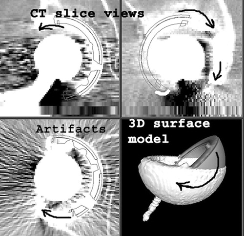
Images were then segmented with an intensity threshold set to a level where only the metallic cup was visually selected. This selection was performed to eliminate metallic image artifacts due to the cup itself. An artifact-free, segmented surface model of the acetabular cup was then generated (). To determine the true, anatomic orientation Citation[11] of the acetabular implant, a graphic CAD (computer-assisted design) 3D model of the cup implant was generated by the software and displayed on the computer screen. Using an intuitive graphic interface, this model was manipulated and overlaid on the segmented cup surface model and the corresponding CT-scan cross-sections (). Its orientation was continuously modified until the best possible match with the surface model was obtained. This final orientation was then recorded as the CT cup abduction and anatomic Citation[11] version.
Figure 1. An acetabular cup surface model obtained after segmentation of CT pelvic images. To eliminate metallic artifacts, the intensity threshold was set at a level where only the cup was selected.
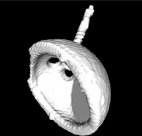
Figure 2. Computer screen view of pelvic CT slices and cup surface model. A CAD (computer-aided design) graphic model of the cup was superimposed on the segmented surface model and its orientation was continuously modified (see arrows) until the best possible match was found between the two models. This final orientation was recorded in terms of cup abduction and version with respect to the previously defined anatomic reference system.
AP X-ray acquisition and analysis using the Xalign matching software
All X-rays were taken in the supine position, with a constant distance between the source and film of 101.6 cm (40 inches). The central X-ray beam was marked with a radio-opaque metallic marker placed over the patient's pubis. The software later used the marker projection on the radiograph to determine the position of the X-ray source. All selected radiographs were scanned with a resolution of 72 dots per inch (dpi), converted into Tagged Image File (TIF) format, and stored on a desktop computer.
The Xalign measurement method consisted of three distinct steps:
First, the software generated a synthetic pelvic AP X-ray using CT pelvic images. This X-ray was centered with the help of the opaque marker mentioned earlier and was “generated” from the same distance (40 inches) as the real X-rays.
On the computer screen, the synthetic X-ray was overlaid on a real pelvic AP X-ray. Using an intuitive interface, the parameters of the synthetic image projection were manipulated until the best intensity match was found (). The 3D pose of the pelvis in the X-ray image was then recovered and the CT anatomic reference system was mapped to the real X-ray. The pelvic orientation was measured as the angle between the APP and the radiographic film plane.
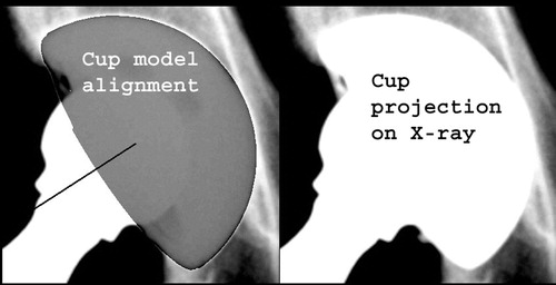
A projection of a CAD graphic model of the cup was then displayed. This represented the virtual X-ray projection of the cup geometric model for a given spatial orientation. The user was able to manipulate the virtual projection and align it with the real projection of the actual cup until the best match was found (). This process allowed measurement of the cup orientation on X-rays, but uncharacteristically using an anatomic reference system (transferred earlier during step 1). The final position was recorded as the Xalign cup abduction and version values.
Figure 3. Computer screen view of the Xalign software interface. A real postoperative AP pelvic X-ray was loaded at upper-right, while a synthetic pelvic X-ray, generated by the software using the CT data, occupied the lower-left quarter. The best possible intensity match between the two images was obtained by overlaying them (upper-left). The anatomic reference system, defined on CT images, was thereby transferred to the examined postoperative X-rays.
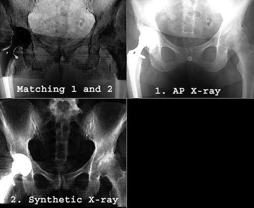
Figure 4. Computer screen view of the last step of the Xalign algorithm. A projection of the CAD model of the cup was overlaid on and matched with the actual X-ray cup projection to determine the cup abduction and version with respect to the anatomic reference system.
Conventional radiographic measurement of cup alignment
In addition, the same set of 43 pelvic AP X-rays was used to measure the cup abduction as the angle between the greater diameter of the cup face and a line tangent to both ischia. The reason for adding this step was to study the relationship between routine radiographic cup measurements and pelvic spatial orientation. There is no consensus in the literature on the accuracy and methodology for cup version measurements from AP X-rays alone. Therefore, in this particular series, the radiographic cup version was not calculated.
Statistical description and analysis
The cup position and pelvic orientation were reported in terms of means, standard deviations and range, using descriptive statistical tools. These values were positive or negative, depending on the calculated differences. The absolute error values were also reported. Pearson coefficient (r) and probability (p) were used for statistical linear correlations performed between different variables. Statistical analysis included Student's t-test to compare the means of two parametric variables. All tests were considered statistically significant if the probability coefficient p was lower than 0.05.
Results
The ground truth: CT cup alignment and pelvic orientation
Nineteen pelvic CT scans were examined, one for each patient in the study. The mean (±standard deviation) CT cup abduction was 52° ± 5° (range: 43° to 59°). The mean acetabular cup version was 18° ± 7° (range: −0.5° to 29°). There were no statistically significant differences between men and women with respect to cup abduction (p = 0.81) or version (p = 0.13).
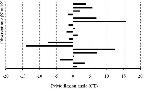
In CT scans, pelvic flexion angles ranged from −14° to 15°, with a mean value of 1.6° ± 6.5° (). This data range represents the anatomic inter-subject variability of the pelvic flexion angles. The absolute values for pelvic flexion had a mean of 4.7° ± 4.6°. The mean pelvic version angle was 1.4° ± 2° (range: −2° to 6°), while the absolute mean pelvic version was 2° ± 1.5°.
Figure 5. Variation of the pelvic flexion angle, as measured from CT scans. The inter-subject variability ranged from −14° to 15° in this limited group of 19 patients.
Cup position and pelvic orientation from AP X-rays using CT/X-ray matching
The X-rays were taken as part of the routine follow-up for patients after THA. Each eligible X-ray was matched with the corresponding postoperative CT data for that particular patient using the Xalign algorithm.
The mean acetabular cup abduction was 54° ± 4.7°, with values ranging from 43.4° to 63.4°, and the mean cup version was 18.7° ± 7.7°, with values ranging from –1.2° to 30.5°. These values for cup version and abduction were then subtracted from the corresponding CT values to obtain the abduction and version measurement errors (with respect to CT-derived cup position values). These measurement errors were 0.8° ± 1.3° for abduction and 0.0° ± 2.0° for version (). The mean abduction and version absolute errors were 1.2° ± 1.0° and 1.6° ± 1.2°, respectively (). The pelvic spatial orientation on X-rays was recorded in terms of pelvic flexion and version. The mean absolute pelvic flexion was 5.8° ± 3.8°, with values ranging from −10.7° to 16° (). These values reflect both the inter-subject and intra-subject variability of the pelvic flexion angle in the studied population. The mean absolute pelvic version angle was 1.5° ± 1.5°. A detailed presentation of pelvic spatial orientation, as determined with the CT/X-ray matching algorithm, is presented in .
Figure 6. Graphic representation of Xalign measurement errors for cup abduction and version.
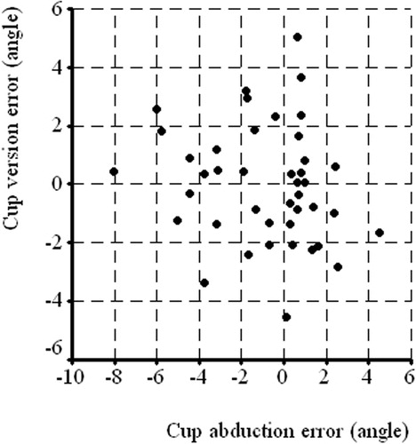
Figure 7. Variation of the pelvic flexion angle measured using the Xalign algorithm.
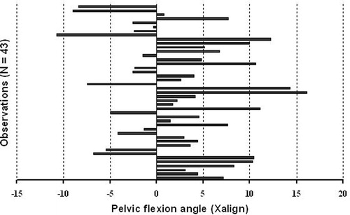
Table I. Xalign errors for cup abduction and version.
Table II. Pelvic spatial orientation angles.
Analysis of the relationship between pelvic orientation and cup measurements
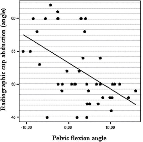
One goal of the present study was to explore the effect of pelvic orientation on measured cup position. The same examined radiographs were used to determine the radiological cup abduction using conventional measurements, as described earlier. The mean abduction was 52.2° ± 5.2°, with values ranging from 44° to 62°. We examined the hypothesis that unknown pelvic flexion could significantly affect the conventional measurement of cup abduction from the AP X-rays. Bivariate two-tailed statistical correlations were performed to study this possible relationship. There was a statistically significant correlation between the abduction values measured conventionally on X-rays and the pelvic flexion angles measured with Xalign. The probability was significant (p = 0.001) and the Pearson coefficient was r = −0.5 (). The same test was also performed for cup position measured using CT/X-ray matching. There was no significant correlation (ns) between abduction or version and the different pelvic angles.
Figure 8. Scatter plot representing the significant correlation between pelvic flexion angle and radiographic measurements of cup abduction (r = −0.5, p = 0.001).
Discussion
Direct CT measurements
The primary focus of this study was to validate the Xalign methodology on clinical data, and direct measurements from postoperative CT scans were used as the ground-truth data. This limited our study to a relatively small sample of 19 patients for whom both postoperative CT scans and X-rays were available. Despite the sample size, we were also able to derive some secondary conclusions about the variability of pelvic orientation that correlate with recently reported studies Citation[16]. The CT cup and pelvic orientation measurements in this study are referenced to anatomic landmarks. Acetabular cup alignment ranged from 43° to 59° of abduction and from 0° to 29° of version. There is a documented relationship between CT cup alignment and pelvic orientation Citation[5–8]. The present study confirms the inter-subject variability in pelvic orientation. The CT supine pelvic flexion angle for only 19 patients varied widely (range: 29°) from −15° to 14° (mean = 1.6° ± 6.5°). This variability was found not only for rotation around the transverse axis (flexion), but also, on a smaller scale, for rotation around the longitudinal axis (lateral version), which ranged from −2° to 6° (mean = 1.4° ± 2°). CT-based measurements reported in the literature do not always use anatomic reference systems. For example, Pierchon and coworkers Citation[13] compared their results to those of Lewinnek et al. Citation[2], concluding that 11 cups situated inside Lewinnek's “safe zone” had dislocated, so cup orientation did not play a major role in the dislocation mechanism. A distinction must be made between the two studies, however, based on the reported methodologies. In Lewinnek's study, the pelvic orientation was standardized for all patients by leveling the anterior pelvic plane, whereas no remarks regarding pelvic orientation are found in Pierchon's analysis.
Artifacts due to the presence of metallic implants represent a real problem for CT data interpretation and measurement. To reduce this effect, some protocols use specially designed software Citation[14]. The methodology of the present CT measurements did not require that additional step. Instead, by simply setting the image intensity threshold at a level where only the metallic cup (and screws, when present) was selected, the automatic CT image segmentation generated an artifact-free 3D cup surface model. This model was then used to measure cup orientation with respect to the anatomic reference system, defined by selecting anatomic landmarks on the CT views.
Xalign validation
The CT/X-ray matching software (Xalign) represented the “engine” of our study. Even though partial results obtained with an older version and different methodologies have already been communicated Citation[15], the present study validated the software using X-ray and CT clinical data. This phase II validation method was based on the comparison between the Xalign measurements and the direct CT measurements used as a “ground truth”. The essence of the matching procedure is that it reconstructs the full 3D pose of both the pelvis and cup from the X-ray image and allows transfer of the anatomic reference system (as determined on the CT) to the examined AP pelvic X-ray. This way, measurements performed on 2D radiographic projections become 3D anatomic measurements. The mean errors, 0.8° ± 1.3° for abduction and 0.0° ± 2.0° for version, are considered to be very good.
The pelvic orientation measured using Xalign included the inter-subject and intra-subject variability. This ranged from –10.7° to 16° for pelvic flexion and from –6.9° to 6° for lateral version.
To study the differences in pelvic location between the standing, supine and sitting positions, Nishihara and coworkers Citation[16] recently reported a similar methodology. However, they used a different approach to the CT/X-ray matching process, calculating and matching different ratios between pelvic diameters measured on AP X-rays and the 3D pelvic CT surface model. No measurement error values were reported for the clinical study, but results of a correlation test on cadaveric pelvic specimens were given (r = 0.99, p < 0.0001). It was found that the supine pelvic flexion variation of the studied patient group (101 patients) was even greater than in our findings, ranging from −37° to 30°. This difference is probably due to the larger study population.
The main source of errors for the algorithm was, without doubt, the matching of the synthetic X-ray with the real radiograph. Finding the best possible match involved a certain degree of subjective judgment, which needs to be assessed by further research. That is why this process should be done automatically, and steps are currently being taken in that direction. Another issue is that these measurements require CT data or some other form of 3D imaging. However, the algorithm requires just one pelvic CT scan that could be obtained at any time preoperatively or postoperatively, then used for multiple postoperative X-ray measurements throughout the patient's life. The applicability of this methodology could eventually be extended to early detection of implant migration or other changes in bone/implant geometry.
The relationship: radiological cup position and pelvic orientation
A statistically significant negative correlation was found between the radiographic abduction values and the pelvic flexion angles (p = 0.001, r = −0.5). This confirms the working hypothesis and means that an increase in pelvic flexion will lead to a decrease in radiographic cup abduction. As mentioned earlier, the same correlation was studied for the anatomic measurements and was not found to be significant. Even if the correlation was not very strong for pelvic lateral version (r = −0.37), it was still present, so a supine patient's left or right turn can influence radiographic measurements.
Anda and coworkers Citation[5] analyzed this relationship in an experimental study using a pelvic anatomic specimen. After metal wires had been taped to the acetabular rims, they radiographed the pelvis at varying degrees of inclination. It was found that the acetabulum “opened up” as reclination increased and “closed” with increasing inclination. The study was repeated, this time using cadavers with unknown hip pathology that were CT scanned at varying pelvic orientations. The authors found that a 1° change in pelvic rotation led to a 0.5° change in acetabular version. This study clearly shows that the effects of pelvic orientation are not limited to radiographic cup measurements: pelvic orientation can also affect CT cup measurements if this variability is not taken into account. Our present clinical study, performed on arthritic patients that had undergone hip replacement, yielded similar results, confirming the experimental anatomic radiology findings mentioned earlier Citation[5]. The inaccuracy of standard radiological cup measurements is currently under evaluation and is the subject of separate research.
Conclusion
The current study validated the Xalign matching algorithm on clinical data and found reasonable accuracy for manual 2D/3D matching. In addition, this technology enabled the study of variability in pelvic spatial orientation and proved that it has significant influence on the radiographic measurement of acetabular cup alignment. Once Xalign becomes entirely automatic in the near future, and following its validation on a larger population, this valuable tool can pass from research to use in everyday clinical routine measurements.
References
- Coventry M B, Beckenbaugh R D, Nolan D R, Ilstrup D M. 2,012 total hip arthroplasties: a study of postoperative course and early complications. J Bone Joint Surg 1974; 56-A: 273–84
- Lewinnek G E, Lewis J L, Tarr R, Compere C L, Zimmerman JR. Dislocation after total hip replacement arthroplasties. J Bone Joint Surg Am 1978; 60: 217–20
- Paterno S A, Lachiewicz P F, Kelley S S. The influence of patient-related factors and the position of the acetabular component on the rate of dislocation after total hip replacement. J Bone Joint Surg 1997; 79A: 1202–10
- Pollard J A, Daum W J, Uchida T. Can simple radiographs be predictive of total hip dislocation?. J Arthroplasty 1995; 10: 800–4
- Anda S, Svenningsen S, Grontvedt T, Benum P. Pelvic inclination and spatial orientation of the acetabulum. A radiographic, computed tomographic and clinical investigation. Acta Radiologica 1990; 31: 389–94
- Eddine T, Migaud H, Chantelot C, Cotton A, Fontaine C, Duquennoy A. Variations of pelvic anteversion in the lying and standing positions: analysis of 24 control subjects and implications for CT measurement of position of a prosthetic cup. Surg Radiol Anat 2001; 23: 105–10
- Siebenrock K, Kalbermatten D, Ganz R. Effect of pelvic tilt on acetabular retroversion: a study of pelves from cadavers. Clin Orthop 2003; 407: 241–8
- Tonnis D, Heinecke A. Acetabular and femoral anteversion: relationship with osteoarthritis of the hip. J Bone Joint Surg 81-A 1999; 12: 1747–70
- McKibbin B. Anatomical factors in the stability of the hip joint in the newborn. J Bone Joint Surg Br 1970; 52(1)148–59
- Jaramaz B, DiGioia A, Blakwell M, Nikou C. Computer assisted measurement of cup placement in total hip replacement. Clin Orthop 1998; 354: 70–81
- Murray D W. The definition and measurement of acetabular orientation. J Bone Joint Surg Br 1993; 75-B: 228–32
- DiGioia A, Jaramaz B, Blackwell M, Simon D, Morgan F, Moody J E, Nikou C, Colgan B, Aston C, LaBarca R, Kischell E, Kanade T. The Otto Aufranc Award. Image guided navigation system to measure intraoperatively acetabular implant alignment. Clin Orthop 1998; 355: 8–22
- Pierchon F, Pasquier G, Cotton A, Fontaine C, Clarisse J, Duquennoy A. Causes of dislocation of total hip arthroplasty. CT study of component alignement. J Bone Joint Surg Br 1994; 76-B: 45–8
- Mian S, Truchly G, Pflum F. Computed tomography measurements of acetabular cup anteversion and retroversion in total hip arthroplasty. Clin Orthop 1992; 276: 206–9
- LaRose D, Cassenti L, Jaramaz B, Moody J E, Kanade T, DiGioia A (2000) Postoperative measurements of acetabular cup position using x-ray/CT registration. Lecture Notes in Computer Science. Proceedings of Third International Conference on Medical Image Computing and Computer-Assisted Intervention (MICCAI 2000), Pittsburgh, PA, October, 2000, S L Delp, A M DiGioia, B Jaramaz. Springer, Berlin, 1935: 104–13
- Nishihara S, Sugano N, Nishii T, Ohzono K, Yoshikawa H. Measurements of pelvic flexion angle using three-dimensional computed tomography. Clin Orthop 2003; 411: 140–51