Abstract
Objective: This paper is focused on prototype development and accuracy evaluation of a medical Augmented Reality (AR) system. The accuracy of such a system is of critical importance for medical use, and is hence considered in detail. We analyze the individual error contributions and the system accuracy of the prototype.
Materials and Methods: A passive articulated arm is used to track a calibrated end-effector-mounted video camera. The live video view is superimposed in real time with the synchronized graphical view of CT-derived segmented object(s) of interest within a phantom skull. The AR accuracy mostly depends on the accuracy of the tracking technology, the registration procedure, the camera calibration, and the image scanning device (e.g., a CT or MRI scanner).
Results: The accuracy of the Microscribe arm was measured to be 0.87 mm. After mounting the camera on the tracking device, the AR accuracy was measured to be 2.74 mm on average (standard deviation = 0.81 mm). After using data from a 2-mm-thick CT scan, the AR error remained essentially the same at an average of 2.75 mm (standard deviation = 1.19 mm).
Conclusions: For neurosurgery, the acceptable error is approximately 2–3 mm, and our prototype approaches these accuracy requirements. The accuracy could be increased with a higher-fidelity tracking system and improved calibration and object registration. The design and methods of this prototype device can be extrapolated to current medical robotics (due to the kinematic similarity) and neuronavigation systems.
Introduction
An Augmented Reality (AR) system generates a composite view for the user that includes the live view fused (registered) with either pre-computed data (e.g., 3D geometry) or other registered sensed data. The result is a combination of the real scene as viewed by the user and a virtual scene generated from 3D geometry/segmentation and accurately co-registered on the display to augment the scene with additional information. Recently, real-time video processing and computer graphics have provided us with the capability to augment the video stream with geometric replicas of the actual objects or sensor data. In neurosurgery, for instance, critical objects of interest within the patient's brain determine the exact size, shape, location and orientation of the craniotomy to be performed. The objects of interest can be tumors, major vessels, or anatomically/physiologically important brain structures. Prior to surgery, several sets of image data (using different modalities such as MRI, CT, SPECT, functional MRI, etc.) are usually scanned. This image data provides important information regarding the spatial arrangement and functional importance of objects of interest within the brain in the image space. Through the process of segmentation and model extraction, these objects/regions can be represented by 3D computer graphics models that can be used as input to the AR system.
One potential field that may benefit from AR technology is medical robotics, an up-and-coming technology with tremendous potential. Direct linkage of medical robotic systems to patient data, and optimal visualization of that data for the surgical team, are of critical importance for successful operations. In their review article on medical robots, Cleary and Nguyen Citation[1] state that if medical robots are to reach their full potential, they must be more integrated systems in which the robots are linked to the imaging modalities or to the patient anatomy directly. They state further that robotics systems need to be developed in an “image-compatible” way. That is, these systems must operate within the constraints of various image modalities such as CT and MRI. This link, it is conjectured, is essential if the potential advantages of robots are to be realized in the medical domain. Medical robots are typically used when the surgeon is away from the operating table, and visual information from the patient site must be augmented in such a way as to allow greater situational awareness and confidence.
Our approach to AR is unique in that it uses a passive articulated arm (Microscribe) to carry the camera that registers the visual image portion of the AR scene Citation[2], Citation[3]. This allows for simultaneous on-demand AR and neuronavigation. We envision a system in which the surgeon can visualize, on demand, critical imaged or sensed data overlaid directly on the video stream at the remote site. This paper describes the implementation and evaluates the accuracy of a prototype AR system using a passive articulated arm (the Microscribe) with a vision system mounted on its end-effector. The paper covers the steps needed to build and compute the real-time augmented scene for objects of interest, and also provides an in-depth error analysis of the finished prototype. In addition, we consider the extrapolation of this prototype to active medical robotic systems and existing neuronavigation systems.
Currently, neuronavigation and robotics systems such as the NeuroMate primarily provide three 2D views (coronal, axial and sagittal) to facilitate awareness of the patient geometry. The surgeon must perform the 2D (image)-to-3D transformation in his mind and also project the envisioned data on his view of the patient. We believe that AR generation is a natural extension of the current systems because it both performs the 2D-to-3D transformation and projects the views directly on the patient view. To illustrate the difficulty of interpreting 2D slices, shows how a simple 3D shape like a cube may be represented by a triangle in the coronal slice, while a vessel appears as two dots in the axial view. Currently, the surgeon must convert these views to a 3D representation and merge it with what he physically sees. This scene represents a virtual reality (VR) scene where the actual live view is not presented. represents a live video view of the same phantom skull with the models of interest displayed directly on the view. This view, generated using our prototype, represents an AR view in which the live view is presented and augmented with additional geometrical information.
Figure 1. (a) Typical data displayed during neuronavigation, representing a virtual environment. (b) Three-dimensional geometry data (models) registered and displayed on a live video view. This represents an augmented-reality view. Note the difference between AR and VR. [Color version available online]
![Figure 1. (a) Typical data displayed during neuronavigation, representing a virtual environment. (b) Three-dimensional geometry data (models) registered and displayed on a live video view. This represents an augmented-reality view. Note the difference between AR and VR. [Color version available online]](/cms/asset/f0a4fb7f-2779-4833-8110-1d35df34c5e8/icsu_a_122145_f0001_b.jpg)
Examples of current robotic systems that could take advantage of this technology include the NeuroMate and Robodoc (both from Integrated Surgical Systems, Inc.), daVinci (Intuitive, Inc.) and Zeus (Computer Motion, Inc.) systems. The NeuroMate robot is used for neurosurgery and assists the surgeon by accurately and stereotactically positioning tools in the surgical field. Our group was the first to perform a clinical procedure using this system in the US, and also provided an in-depth accuracy assessment of it Citation[4]. This system takes advantage of links to the patient image data and connects the robotic movements to the knowledge base of patient-specific image data and structures. For instance, the kinematic positioning software system knows if the arm is about to intersect with the patient. The system software (VoXim™, IVS Software Engineering, Chemnitz, Germany) allows precise image-based planning and visualization of multiple trajectories. Although this system is image data linked, it is not a master-slave dexterous device and does not have an AR interface.
Systems like Zeus and daVinci (both presently in use at our collaborating sister facilities) are master-slave systems for minimally invasive surgery. They have both made enormous technological leaps in terms of master–slave control systems that are sufficiently robust for the fidelity needed for medical applications. These systems allow the surgeon to be located away from the surgical site and enable control of traditional laparoscopic instruments with hand-controllers. At the robot–patient interface, these systems are equipped with three robotic arms to emulate the three tools of laparoscopic surgery. Two arms (with tools mounted on them) are used for surgical manipulation and the third arm has an endoscope for visualization. The endoscope can be controlled effectively using voice-recognition technology. The system is able to modulate the surgeon's motions by tremor filtration, and can also use a technique of motion scaling to translate centimetric motions by the surgeon into sub-millimetric motions at the robot-patient interface, thus allowing more precise microsurgery. These robots are commercially available systems, but lack a link to the patient imaging information and therefore have no AR capability. Visualization of the structures of interest prior to surgery would greatly enhance the surgeon's ability to position the three small laparoscopic port placements on the patient. Incorrect placement of these ports can drastically affect the success of such surgeries.
The narrow field of view in laparoscopic surgery makes it hard for the surgeon to recognize internal organs. In addition, due to the fact that the video views obtained from the scope are sometimes not in the surgeon's frame of reference (left/right or up/down may be tilted), he can become disoriented. Therefore, an AR system may bring significant improvement to the robotic laparoscopic surgery procedure. During surgeries, fixed critical objects overlaid on the video stream could provide additional situational awareness cues. The robot arms could also be augmented when not in direct view. It is the thesis of this paper that the potential exists for these (and other upcoming) systems to use augmentation technology to provide the surgeon with a direct link to patient pre- and/or intra-operative images (e.g., ultrasound data, open MRI data) and other sensor data. The aim of this paper is to prove the utility and accuracy of this technology and to provide an easily translatable kinematics-based AR prototype.
Related work
A landmark paper on registration methods for image-guided surgery and enhanced visualization was presented by Grimson et al. Citation[5]. In this paper, an augmentation scene of a static camera system was produced using a laser range scanner and a video camera. A laser scan of the patient produced a set of range data, which was manually separated to include just the patient and the region of interest. Next, the data was manually matched to the video frame, and a computer-controlled refinement stage that cycled through all possible pairings of the MRI points to laser points produced the necessary AR transformations. The authors stated that augmentation of a stationary video camera is relatively straightforward, but [dynamic] tracking of the camera is “more relevant and more challenging”. They reported a registration RMS error for their system of 1.6 mm, but admitted that this error was the error of data-fitting and that it was difficult to ascertain the actual registration error. Their future work was to include “some kind of phantom study”. In our study we provide this accuracy study.
Alcaniz Raya et al. Citation[6] have proposed an AR prototype to replace the traditional optical microscope view with a digital one. For their prototype, they used an infrared tracking system and two video cameras tracked by infrared LEDs. They considered two types of error for their prototype error analysis: object space error and camera calibration error, neither of which can provide a reliable foundation for error analysis. The first measure is obtained by finding the closest approach between the point in object space and the line of sight formed by back-projecting the measured 2D coordinates out through the camera model. The second measure is defined as the distance between the actual and image points as projected on the screen, which is obviously not caused by camera calibration error alone. The authors reported errors of 0.2 ± 0.15 mm and 0.4 ± 0.2 mm for what they called “object space error” and “camera calibration error,” respectively. Our experience has been that typical infrared tracking devices have an error on the order of 1 mm. Although each LED typically has an error on the order of just 0.35 mm, determination of tool-tip position (which is extended beyond the LEDs) requires at least 3 such LEDs and thus leads to greater error Citation[7]. Moreover, Alcaniz Raya et al. used the anatomical structures/points of the skull surface to measure the error, which is, based on our experiences, a very subjective and inaccurate approach.
Hattori et al. Citation[8] have developed a data fusion system for the daVinci robotic surgical system, comprising an optical 3D location sensor and a digital video processing system. In a clinical situation, however, the proposed system must be calibrated/registered to calculate the transformation from the optical marker to the camera. This extra step should be undertaken prior to each surgery. In their paper, these authors did not present comprehensive results or an accuracy study for the daVinci system and their infrared tracking system as used to generate an AR scene. Neither was a rigorous error analysis reported. Also, their system did not use the robot's kinematics and involved additional infrared hardware that required active LEDs in continuous line-of-sight view of an infrared camera.
Khamene et al. Citation[9] have developed an AR system for MRI-guided needle biopsy. Their main goal is to reduce or completely eliminate the need for interventional scanning (by a high-field closed magnet MRI), as well as the need for an open MRI scanner in the biopsy procedure. Their system consists of 1) a video-see-through head-mounted display (HMD); 2) two video cameras attached to the HMD to provide a stereo view of the scene; 3) a third video camera for tracking; 4) a set of optical markers attached to the patient's bed; and 5) a set of optical markers attached to the needle. In their analysis, they overlay the model of the skin of the patient on the patient. It seems to us that having the patient's skin overlaid by a needle does not really provide any useful additional information for a biopsy procedure. What may be essential for this application is the position of the needle in the MRI image space during the procedure. Khamene et al. have reported accuracy as high as 1 mm for the whole system, but our experience suggests that this degree of error is typical of tracking devices by themselves. The authors pointed out that, for a small number of cases where the accuracy measurement was substantially greater than 1 mm, the errors were most likely caused by needle bending. The line-of-sight problem is also a limitation for this type of tracking method.
In their paper on a data fusion environment for multimodal neuronavigation, Jannin et al. Citation[10] briefly experimented with AR techniques as applied to the Zeus microscope. They used projected 2D contours in the focal plane of the right ocular of the microscope. The main limitations noted were that no information about structures before or behind this plane was visible, and that different contours could not be visualized with different colors, line widths, or labels. No error estimates were provided for the augmentation technique used.
To generate an accurate AR scene, it is necessary to set up a virtual camera that models the actual camera accurately. There is a large body of research in this regard Citation[11–14], including a key paper by Tsai Citation[11]. We used Tsai's camera model, as used by Weng et al. Citation[15], and refined by Heikkila Citation[14]. Heikkila also provided a very useful implementation.
We propose that robotics technology can borrow the techniques developed in image-guided surgery for dynamic tracking and object registration, and the visualization capabilities inherent in AR, to link the surgeon with the patient imaging data directly. In this paper, we present a prototype device that is a simulation of the visualization arm of a robotic system (e.g., the third arm of the Zeus or daVinci system). We first cover the methods involved in creating an AR prototype, namely camera tracking, camera calibration, and camera mounting/pose determination. Next we discuss the errors involved in creating this prototype, namely the Microscribe arm intrinsic error, camera calibration errors, and image data error, and the overall application accuracy of the system. Finally, we discuss the utility of such a system for robotics and neuronavigation systems.
Materials and methods
Augmented reality represents an extension to image-guided surgery by integrating an end-effector-mounted camera (see ). Image-guided surgery uses a method that transforms the trajectories of tracked tools such that they can be displayed to provide accurate and reliable image-to-surgical-space guidance. The methodology involves three components: image acquisition, with definition of coordinated space from one or more imaging modalities; planning or simulation of the surgical procedure; and intraoperative surgical procedures, which include the determination of the spatial relationship between the image and the surgical coordinate space (patient registration). shows an image-guided system that we have integrated, in which a socket interface to the Microscribe allows multiple clients on the internet to view the tracking of the device endpoint on the 3D slices and graphical representation of the phantom in 3Dslicer Citation[5]. The critical component in interactive image-guided surgery is the use of an intraoperative localizer system or digitizer, which ultimately provides the surgeon with useful navigational information, usually in the form of the position and/or orientation of surgical instruments. Infrared tracking is one of the most popular methods used in stereotactic neurosurgery. Robotics (as in the case of the NeuroMate system) is another very good method. The key advantages of robots are that they can effectively position, orient and manipulate surgical tools in 3D space with a high degree of accuracy. Using the well-developed and now-standard techniques of image guidance (), and adding a photographic video camera (), camera registration software, and video/graphics mixing software, an AR scene can be generated ().
Figure 2. Neuronavigators: the precursor of augmented reality. (a) We use the Microscribe as the tool tracker. The position and orientation of the end-effector is shown on the orthogonal slices and 3D model of the phantom skull. After adding a calibrated and registered camera (b), an augmented reality scene can be generated (c). [Color version available online]
![Figure 2. Neuronavigators: the precursor of augmented reality. (a) We use the Microscribe as the tool tracker. The position and orientation of the end-effector is shown on the orthogonal slices and 3D model of the phantom skull. After adding a calibrated and registered camera (b), an augmented reality scene can be generated (c). [Color version available online]](/cms/asset/6afe3bd5-fafd-4dc5-92e1-51cf42f16fae/icsu_a_122145_f0002_b.jpg)
The steps involved in generating a medical AR scene are illustrated in . Following image data collection and segmentation of the objects of interest, the creation of 3D graphical models (required for augmentation) can be completed. This step can also be performed for image guidance, but is not necessary since the orthogonal views of the imaging modality can suffice for navigation (and are frequently the only ones used for this purpose). The key differences between neuronavigation and augmented reality are the camera parameter estimation, the camera mounting, and the mixing of the live video and graphics. Camera parameter estimation (camera calibration), to build up a virtual camera that closely models the actual camera, and mounting and pose estimation of the camera need only be performed once for the system, but can be repeated periodically for verification purposes. These two steps are covered in more detail below. When generating the graphical view of the virtual objects, the relative spatial positions and orientations of the virtual camera and virtual objects at this step are the same as those of the actual camera and actual objects of interest. Furthermore, the virtual camera and virtual objects model their actual counterparts very accurately. This allows the graphical view of the virtual objects to be seen from the actual camera point of view on the live video if the objects of interest are visible. The mixing of the live video Citation[16] from the actual camera with the graphical view from the virtual camera enables the surgeon to see the segmented objects of interest projected on the video view from any perspective and at any depth.
Figure 3. Steps required to generate both a neuronavigation system and an augmented reality system. Note that AR represents an extension to neuronavigation and can be performed simultaneously with it. [Color version available online]
![Figure 3. Steps required to generate both a neuronavigation system and an augmented reality system. Note that AR represents an extension to neuronavigation and can be performed simultaneously with it. [Color version available online]](/cms/asset/5d1fae86-9829-4f54-9ab9-bab82be70ab1/icsu_a_122145_f0003_b.jpg)
Creating the virtual objects is a necessary step for generating an AR environment based on imaging. For medical applications, each patient has a unique set of objects that can be used for augmentation. Usually, these objects are tumors, skin surfaces, major vessels, and relevant normal or abnormal structures in the brain. We define our object model by a segmentation procedure that uses medical imaging data (see ). Another form of augmentation can come from the augmentation of sensor data for which both the position and sensor values are known. We have chosen 3Dslicer software that is freely available and is open-source. This has been developed in collaboration between the MIT Artificial Intelligence Lab and the Surgical Planning Lab at Brigham & Women's Hospital, an affiliate of Harvard Medical School. 3Dslicer can generate an output file in modeling VTK format for which we have written parsers within our software (see ). It has several important tools available for segmentation Citation[5].
Tracking of the camera
We have researched view augmentation of a camera that can be mounted on the end-effector of an articulated arm. The live views from the Microscribe end-effector camera will have synthetically generated 3D graphical views of the structures overlaid on them. In our prototype, a miniature camera (Watec LCL-628, 7.5 mm diameter, 330 TV lines, 3.9-mm lens f2.8 [H-52°, V-40°]) is mounted on the end-effector of the Microscribe device. This is an articulated arm, but its geometric and transformation structural similarities make it an inexpensive and useful analog to current robotic systems in terms of experimentation with AR technology. It has the advantage of being readily accessible and amenable to quick prototype development and evaluation. We have integrated the serial interface with the 5-degree-of-freedom Microscribe, and can obtain a precise position and orientation of the camera with respect to the AR interface. We have thus generated a prototype augmented robotics system using this device.
In , a forward kinematics solution (i.e., the end-effector of the Microscribe coordinates in terms of the base coordinates) would be defined as the concatenation of all the individual joint transformation matrices. Each individual transform specifies how the first joint is related to the second joint. The combination of the 4 × 4 homogeneous transformation matrices defines the position and orientation of the end-effector in the base coordinate system.Additional transformations are needed to compute the required AR transformation. A relationship between the object (O) that is to be augmented and the camera coordinate system (C), (TO−C), must be derived. This transformation is computed by knowing the transformation from the object to the base of the Microscribe (TO−B), the measured transformation from the base of the Microscibe to the end-effector (TB−EE), and the transformation from the end-effector of the Microscribe to the CCD of the camera (TEE−C):
The computed relationship of Equation 2 allows alignment of the actual camera coordinates with the coordinate system of the virtual graphics camera. One of the key registrations that must be performed is object (patient) registration (TO−B). This transformation is computed using a pair-point matching that is also performed in standard neuronavigation systems (see ). Knowing a set of matched points (we use 5 pair-points; the minimum is 3) between the actual patient (phantom) and the tomographic image space, an iterative algorithm to optimize the transformation parameters can result in the needed transformation. The Levenberg–Marquardt optimization method Citation[17] has been shown to provide a fast convergence, and we have used this algorithm in our implementation of pair-point matching. In the next section, details of the method (based on the pattern-based estimation of the extrinsic camera parameters) for the essential computation of the transformation TEE−C will be provided.
Figure 4. The transformations needed to compute the required transformation from the end-effector to the camera coordinates TEE-C. [Color version available online]
![Figure 4. The transformations needed to compute the required transformation from the end-effector to the camera coordinates TEE-C. [Color version available online]](/cms/asset/b27c7d53-8670-4d5d-bb26-e928538c1ed4/icsu_a_122145_f0004_b.jpg)
Computing the pose of the camera relative to the end-effector (TBB-C)
Camera calibration is a protocol for the computation of both the camera optical characteristics (intrinsic parameters) and its 3D position and orientation (extrinsic parameters). Using the camera parameters estimated by the calibration technique described in the next section, the camera viewpoint is calculated relative to the real-world marker (pattern) shown in . In general, camera parameter estimation involves moving the camera viewpoint relative to a geometrically well-defined pattern. Both the intrinsic (camera model) parameters and the extrinsic (pose) parameters are estimated. Once the intrinsic parameters are known, the extrinsic parameters (pose) relative to any pattern view can be readily computed in one step (see the next section for more details).
In this work, we take advantage of the estimation procedure to calculate the transformation matrix from the pattern to the camera coordinates systems (TP−C). First, the pattern used for camera calibration was rigidly fixed relative to the base of the Microscribe. The location and orientation of the pattern's coordinate system (relative to the Microscribe's base) was then calculated using three collected points on the pattern (digitized with the Microscribe). The first point (P0) was the origin of the coordinate system; the second point (P1) was a point along the x-axis of the pattern coordinate system; and the third point (P3) was a point along the y-axis. At this point, the vectors in the x and y directions, Vx and Vy, were computed as follows:The vector in the z-direction was computed simply as the following cross-product.
These three vectors, along with the point P0, form the 4 × 4 homogeneous transformation matrix from the base coordinate to the pattern coordinate systems (TB-P) as follows:
The above transformation matrix can be described in terms of the projection of the unit vectors of the pattern coordinate system onto the base coordinate system and a transition vector from the origin of the pattern to the origin of the camera coordinate systems. Knowing the above transformation from the base of the Microscribe to the pattern (TB-P), the transformation from the base of the Microscribe to the end-effector (TB-EE), and the transformation from the pattern to the camera coordinates (TP-C), the needed transform from the end-effector of the Microscribe to the camera (TEE-C) can be derived as follows:
Camera calibration used to determine TP‐C
Camera calibration is a very important issue for AR and hence is described in brief here for clarity. The camera calibration algorithm is used in this research to 1) model the actual camera to be used for graphical view generation, and 2) estimate the transformation matrix between the end-effector and the camera coordinates by using the technology to compute the transformation TP-C. represents a camera model and the associated variables for the estimation of the necessary parameters.
Figure 5. Camera calibration model. Objects in the world coordinate system need to be transformed using two sets of parameters—extrinsic and intrinsic.
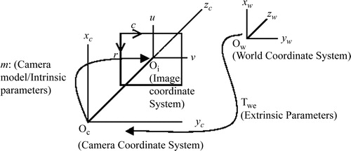
Camera parameters are divided into intrinsic parameters (the focal length, principal point, skew coefficient, and radial/tangential distortions) and extrinsic parameters (the position and orientation of the camera). The extrinsic parameter matrix (Twc), represented below by the matrix of r and t parameters, is needed to transform objects from the world-centered to the camera-centered coordinate system as follows:The intrinsic and extrinsic parameters are derived from a two-step process that involves first a closed-form (pinhole model) solution to approximate the parameters, and then an iterative non-linear solution to obtain accurate parameters. In a pinhole model of the camera (which ignores the radial and tangential distortion parameters), each point in the world coordinate system is projected via a straight line through the projection center to the image plane. This model of the camera system only approximates the real camera projection as follows:
However, by using the pinhole model, the initial estimates to the minimization process to be described can be provided by using a direct linear transformation (DLT). The DLT was first described by Abdel-Aziz and Karara Citation[13]. In the first step, given N control points in the world coordinate system (xw, yw, zw) and their corresponding CCD array points (ri, ci), the camera parameters in vector a can be computed by solving the following equations:
The parameters in vector a can be estimated with least-square methods, since Equation 11 is homogeneous (the right side is a zero vector). Note that, as this solution is based on a pinhole model, lens distortion is not considered. This step, however, gives an initial guess for the iterative nonlinear optimization method discussed next.
A brief overview of typical calibration process is given here. Let (xw, yw, zw) represent the coordinates of any visible point P in a fixed coordinate system (world coordinate system), and let (xc, yc, zc) represent the coordinates of the same point in a camera-centered coordinate system. It is assumed that the coordinates of the camera-centered coordinate system coincide with the optical center of the camera, and that the zc axis coincides with its optical axis. The image plane, which corresponds to the image-sensing array, is assumed to be parallel to the (xc, yc) plane and at a distance f from the origin (see ). The Tsai model governs the following relationships between a point of the world space (xw, yw, zw) and its projection on the camera CCD (ri, ci):
Here, R (the rotation component) = (rij) is a 3 × 3 rotation matrix defining the camera orientation, and T (the translation component) = (t1, t2, t3)TThese equations need to be formulated in an objective function so that finding the optimum of the function leads us to the camera parameters. The camera parameters are r0, c0 (image centering), fu, fv (effective focal lengths), radial (k) and tangential (g1, g2, g3, g4) distortions, and Twc (extrinsic parameters).
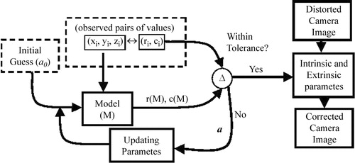
Our objective function is as follows:where m is Tsai's camera model, (ˆ ri, ˆ ci) is our observation of the projection of the ith point on the CCD, and (ri(m), ci(m)) is its estimation based on the current estimate of the camera model. The above objective function is a linear minimum variance estimator Citation[17]. Note that we have n observed points in the world space. illustrates the optimization of these parameters. n pairs of points are collected for which the world coordinates (xw, yw, zw) and the CCD coordinates (ri, ci) are known. An initial guess of the extrinsic parameters is provided by the DLT method described above (Equations 10 and 11). After an initial guess, the camera model parameters (a) are used to compute model estimated values of (r, c) for the entire data set (Equations 12–15). These values are then compared with the measured values using the objective function (Equation 16). If a certain tolerance is met, the final parameters are reported. This tolerance value is the error that needs to be accepted (as the camera model is not perfect) in order to terminate the computation. The Levenberg–Marquardt optimization method has been shown to provide a fast convergence. It works very well in practice and is considered to be the standard for non-linear least-squares routines Citation[17]. Note that the extrinsic parameters estimated here (R and T) form the matrix needed in Equation 7: (TP-C). More details of this technology can be found in the publication by Heikkila Citation[14].
Figure 6. Camera parameter estimation. An initial guess of the extrinsic parameters comes from the DLT method. The observed CCD array points and the corresponding computed values are compared to determine if they are within a certain tolerance. If so, the iteration ends.
Error analysis methods
To measure the accuracy of the AR system with imaging data (CT), it was first necessary to evaluate the error of the AR portion of the technology. To do this, we isolated the error of the AR system from the errors inherent in imaging and segmentation. A method was chosen that did not involve either imaging or segmentation components. We then performed a similar experiment using a phantom skull imaged with CT data. For the non-imaging test, a stereotactic phantom ring was used for the evaluation of the error of the system (see ). This ring is equipped with a moveable pointer for which the 3D position can be accurately read. The phantom is known to be mechanically very accurate (within 0.5 mm) and has been used as a gold standard in several of our previous studies that measured the accuracy of robotic devices and standard stereotactic systems Citation[4]. This device allowed us to pinpoint markers in the video image using the stereotactic phantom's 3D position pointer. We first chose several points on the surface of the ring for which we knew the exact location relative to the ring's coordinate system. These were the points that were used for the pair-point matching to determine the pose of the ring relative to the base of the Microscribe. A model of a cube with known dimensions was then created and placed at the center of the phantom space. We first placed the phantom's pointer at the known location of each of the corners of the cube. The corner of each of the cube points was then viewed from orthogonal view directions to determine the error along each individual axis. To compute the error for each point, it was necessary to know the distance from the apex of the pointer to the corner of the virtual cube along all three axes. If we were to apply the distance equation (Equation 17), we would obtain the error for that point.However, we took three orthogonal views of the cube corners and each view contained two of the error measures. For instance, a view from the x-direction would give us the errors along both the y- and z-axes. To derive the necessary equation (Equation 17), we used all three orthogonal views that were captured and determined the two deltas for each view (see ). The distance squared in which the camera was positioned on each of the orthogonal axes (x, y and z) was computed as follows:
It is clear from these equations that the actual error reduces down to Equation 17 (after taking into consideration all three views of the cube corner) as follows:
Since the orthogonality of the view direction was critical, the camera was repositioned until the axis orthogonal to the image plane of the cube disappeared. shows that if the apex of the pointer is viewed from an orthogonal angle, the cube appears as a square. The captured video frames were analyzed to ascertain the pixel error observed between where the actual cube corners should have been located (on the apex of the pointer) and where they were in the augmentation (cube corner). This distance represents the 2D error from that view. The deviation can be easily seen and measured very accurately both in terms of pixel error and actual mm error when scaled from a known distance in an image. The cylindrical geometry of the ZD frame pointer provides a scaling reference to transfer from the pixel-wise error measurements to an absolute value error space.
Figure 7. A cube is augmented on the live video from the Microscribe. Three orthogonal views are used to compute the error: (A) represents a close-up view of the pointer (the known location of the cube corner) with the video camera on the x-axis; (B) is the pointer as viewed from the y-axis; and (C) is the pointer viewed from the z-axis. (D) represents an oblique view of the scene with the entire cube viewed. [Color version available online]
![Figure 7. A cube is augmented on the live video from the Microscribe. Three orthogonal views are used to compute the error: (A) represents a close-up view of the pointer (the known location of the cube corner) with the video camera on the x-axis; (B) is the pointer as viewed from the y-axis; and (C) is the pointer viewed from the z-axis. (D) represents an oblique view of the scene with the entire cube viewed. [Color version available online]](/cms/asset/76ca5e26-92c2-4a84-865e-d9c3d3d545d1/icsu_a_122145_f0007_b.jpg)
Results
In this section, we first describe the accuracy of the Microscribe system and of the camera calibration procedure, and then discuss the contribution of all the individual errors to the application error of the entire prototype.
Accuracy of the Microscribe
To assess the accuracy of the AR scene, we first determined the accuracy of the Microscribe measurement device. First, 40 measurements were taken of the same point using the device. It was found that the average RMS difference between these points was 0.732 mm. In a further experiment, a known distance of 50 mm was measured 10 times using the Microscribe. The average error for this measurement was 0.841 mm. Although a more rigorous accuracy study could be conducted, we are confident that the error of the Microscribe is within 1 mm.
Accuracy of camera calibration
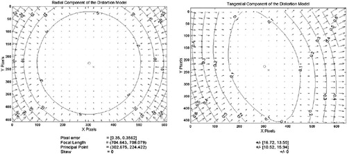
In camera calibration, a set of parameters is defined which serve to model the optics of the actual camera. These measures are derived by the minimization of error, as described in the Materials and methods section. For the camera we used the set of parameter values shown in . These parameters allow for the correction of various image distortions that occur with cameras. The major parameters of this camera model are the focal length, the principal point, and the radial/tangential distortions. After using the modeled values, the image can be regenerated to produce the undistorted image. When this undistorted image is compared to the ideal image (based on the grid pattern), a pixel error can be computed for the images. The average pixel errors reported were 0.350 pixels for the x-axis and 0.356 pixels for the y-axis. The contour lines in the images represent the error boundaries at that location in pixels. Notice that for the radial distortion at the center of the image (, left), the errors are all less than 5 pixels and converge to 0 pixels at the very center. Notice also that the errors at the corners of images are in the range of 25 pixels of error. The tangential components (, right) are in the range of approximately 0.1 pixels and play a minor role relative to the radial distortion. Hence, the overall camera distortion is primarily due to radial distortion.
Figure 8. Errors of the distorted image. The contours represent error boundaries. Note that for radial distortion at the center (left) there is less than 5 pixels of error and at the corners the errors exceed 25 pixels. The tangential distortion is an order of magnitude less than the radial distortion.
Total application error dependencies
The total error of the system was computed both with and without using image data. First, an error measurement was made without using imaging data. For this method, the average error over the 10 measurements taken across the field of view of the camera and covering the maximum extent of the phantom was 2.74 mm, with a standard deviation of 0.81 mm and a maximum error of 4.05 mm. To ascertain the additional error introduced by inclusion of the imaging data, another experiment was performed in which 10 fiducials visible in the CT scan were digitized and their locations recorded. Spheres of 1 mm diameter were then modeled and placed on top of each of the markers at the locations predicted by the augmentation. The pixel error as well as the scaled mm error was computed for each of the fiducials. The measured error of the location of the fiducial in the AR scene was 2.75 mm on average, with a standard deviation of 1.19 mm and a maximum error of 5.18 mm. The effect of adding the CT-scan data was negligible.
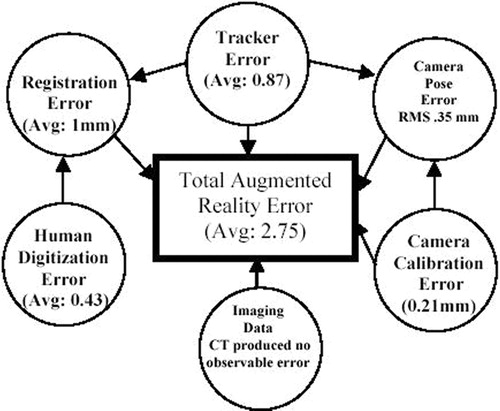
illustrates the individual component errors involved and their dependencies and contributions to the overall application system. The total AR error is dependent on several different types of error. The tracker (Microscribe) is a key source of error and influences several other error estimations (camera pose determination and registration error). Registration error (the error involved in determining the transformation from the base of the tracker to the objects being augmented) is dependent on how accurately the actual points on the patient can be captured. In this method, actual points are captured and matched with their image counterparts. Hence, digitizer accuracy is an important factor. In addition, registration error also involves human digitization error that relates to the fact that a human can only achieve the actual point with an accuracy of 0.43 mm on average. We ascertained this error by digitizing the same point from several different angles (10 different values) and report the variation in the measured values. In addition, the center of a typical fiducial is not represented by a single point, but by a circle approximately 0.5 mm in diameter. This geometry can also lead to digitization errors. A better fiducial design would have the center of the fiducial be a cone (rather than a cylinder) that culminates in a single point. Furthermore, the computation of the camera pose relative to the end-effector of the tracker also requires the use of digitized/tracked data. To determine the camera pose relative to the end-effector of the Microscribe, we used a method that required the extrinsic camera parameters to be computed using the camera calibration techniques and also the tracker end-effector transformation information (see the Materials and methods section). Since it was not possible to measure the actual camera position and orientation with the precision required, we computed the pose matrix from 5 different camera angles and report the standard deviation of the measured values. For the position component, the values had a standard deviation of 0.13, 0.30 and 0.13 mm in the x-, y- and z-axes, respectively. These standard deviation values indicate that there is an RMS mm standard deviation of about 0.35 mm. For camera calibration, there was a pixel error of approximately 0.35 pixels. This corresponded to an error of 0.21 mm of error that could be attributed to errors in the camera calibration. Imaging data plays a critical role in the accuracy, but we have found no significant distortion error from the CT acquired. We conjecture that MRI or ultrasound data would have more distortion and exert a greater influence on the application accuracy. We have accounted for the majority of the observed error (2.43 mm of the total 2.75 mm): It is possible that the imaging data played a role in producing some of the error of the system that is unaccounted for.
Figure 9. Errors involved in augmented reality.
Discussion
Currently, neuronavigation systems primarily offer three 2D views (coronal, axial and sagittal) to provide awareness of the patient geometry. The surgeon must perform the 2D (image) to 3D transformation in his mind and also project the envisioned data onto the view of the patient. We believe that augmented reality (AR) generation is a natural extension for the surgeon because it performs both the 2D-to-3D transformation and projects the views directly on the patient view. We have already illustrated the difficulty in interpreting 2D slices. In , a simple 3D shape like a cube is represented by a triangle in the coronal slice, while a vessel is represented by two dots in the axial view. This does not seem like the natural method of visualization, and was part of the motivation for this work. We have recently completed a 20-subject human factors study showing the advantages and disadvantages of AR as compared to neuronavigation from the usability perspective; this is considered in detail in reference 18.
This paper is focused on prototype development and accuracy evaluation of a medical AR system. A passive articulated arm (Microscribe) was used to track a calibrated end-effector-mounted video camera. Due to its kinematic similarity to robotic systems, this method potentially represents an efficient and intuitive way to link robotic systems and the surgeon to the patient data in an AR environment. In our prototype, the user, following registration, is able to navigate in and around a phantom and visualize in real time the objects of interest, highlighted with wire frame models, from any angle and distance. In this case, we superimpose the live video view with the synchronized graphical view of CT-derived segmented object(s) of interest within a phantom skull. Since the accuracy of such a system is of critical importance for medical use, it was considered in detail. It should be noted that the errors here represent static error: error due to brain or organ shifting is not considered. Intraoperative imaging methods (open MRI or ultrasound) need to be integrated to take into account dynamic changes during surgery. We analyzed the individual contributions and the system accuracy of the prototype. The AR accuracy mostly depends on the accuracy of 1) the tracking technology; 2) the camera calibration; 3) the image-scanning device (e.g., CT or MRI scanner); and 4) the object segmentation. The various accuracy measurements are shown on . After using data from a 2-mm-thick CT scan, the AR error was measured at 2.75 mm with a maximum error of 5.2 mm. This error is on the borderline of acceptability for neurosurgical applications (one of the most demanding fields in terms of accuracy requirements).
The overall accuracy of the system could be improved in several ways. In the first place, a higher-fidelity tracking system could be used. The tracking device in this case contributes about one third of the error because it is involved not only in the tracking of the camera, but also in the registration of object space relative to its base. In the registration phase, at least 4 points must be digitized using the tracker. The process of camera calibration can also be improved by choosing a more accurate algorithm, e.g., our proposed method Citation[15]. From this study, we have built a prototype that approaches the error requirements imposed by neurosurgery. We have also given details of the implementation of this prototype such that it can be recreated. We conjecture that medical robotic devices of the future should be able to use this technology to directly link these systems to patient data and provide optimal visualization of that data for the surgical team. The design and methods of this prototype device can also be extrapolated to current medical robotics systems and neuronavigation systems.
Acknowledgments
The authors would like to thank Dr. Lucia Zamorano for the use of the ZD frame and a phantom, and for the initial support for this work. In addition, they would like to thank Drs. Jianxing Gong and Qing Hang Li for their engineering assistance. Finally, they would like to thank Drs. Farshad Fotouhi and Hamid Soltanian-Zadeh for financial support and review of the manuscript. This work was partially supported by NASA grant 99-HEDS-01-079.
References
- Cleary K, Nguyen C. State of the art in surgical robotics: clinical applications and technology challenges. Comput Aided Surg 2001; 6: 312–28
- Pandya A K, Siadat M, Zamorano L, Gong J, Li Q, Maida J C, Kakadiaris I (2001) Tracking methods for medical augmented reality. Lecture Notes in Computer Scienc. Proceedings of Fourth International Conference on Medical Image Computing and Computer-Assisted Intervention (MICCAI 2001), UtrechtThe Netherlands, October, 2001, W J Niessen, A Viergever, M. Springer, Berlin, 2208: 1406–8
- Siadat M, Pandya A K, Zamorano L, Li Q, Gong J, Maida J. Camera calibration for neurosurgery augmented reality. Proceedings of 6th World Multiconference on Systemics, Cybernetics and Informatics, Orlando, FL, July, 2002, 14–19
- Li Q, Zamorano L, Pandya A K, Perez R, Gong J, Diaz F. The application accuracy of the NeuroMate robot—a quantitative comparison with frameless and frame-based surgical localization systems. Comput Aided Surg 2002; 7: 90–8
- Grimson W EL, Ettinger G J, White S J, Lozano-Pérez T, Wells W M, III, Kikinis R. An automatic registration method for frameless stereotaxy, image guided surgery, and enhanced reality visualization. IEEE Trans Med Imaging 1996; 15: 129–40
- Alcaniz Raya M, Varvaro Marcinek H, Martinez Saez JM, Torres Sanchez R, Juan Lizandra MC, Monserrat Aranda C, Gil Gomez JA. Mixed reality for neurosurgery: a novel prototype. Medicine Meets Virtual Reality 11, J D Westwood, H M Hoffman, G T Mogel, R Phillips, R A Robb, D Stredney. IOS Press, Amsterdam 2003; 11–15
- Li Q, Zamorano L, Jiang Z, Gong J, Pandya A K, Perez R, Diaz F. Effect of optical digitizer selection on the application accuracy of a surgical localization system—a quantitative comparison between the OPTOTRAK and FlashPoint tracking systems. Comput Aided Surg 1999; 4: 322–7
- Hattori A, Suzuki N, Hashizume M, Akahoshi T, Konishi K, Yamaguchi S, Shimada M, Hayashibe M. A robotic surgery system (da Vinci) with image guided function—system architecture and cholecystectomy application. Medicine Meets Virtual Reality 11, J D Westwood, H M Hoffman, G T Mogel, R Phillips, R A Robb, D Stredney. IOS Press, Amsterdam 2003; 110–6
- Khamene A, Wacker F, Lewin J. An augmented reality system for MRI-guided needle biopsies. Medicine Meets Virtual Reality 11, J D Westwood, H M Hoffman, G T Mogel, R Phillips, R A Robb, D Stredney. IOS Press, Amsterdam 2003; 151–7
- Jannin P, Fleig O J, Seigneuret E, Grova C, Morandi X, Scarabin J M. A data fusion environment for multimodal and multi-informational neuro-navigation. Comput Aided Surg 2000; 5: 11–17
- Tsai R. A versatile camera calibration technique for high-accuracy 3D machine vision metrology using off-the-shelf TV cameras and lenses. IEEE J Robotics Automation 1987; RA-3: 323–44
- Wang L, Tsai W. Camera calibration by vanishing lines for 3-D computer vision. IEEE Trans Pattern Anal Machine Intell 1991; 13: 370–6
- Abdel-Aziz Y I, Karara H M. Direct linear transformation into object space coordinates in close-range photogrammetry. Proceedings of Symposium on Close-Range Photogrammetry, Urbana, IL, 1971, 1–18
- Heikkila J. Geometric camera calibration using circular control points. IEEE Trans Pattern Anal Machine Intell 2000; 22: 1066–77
- Weng J, Cohen P, Herniou M. Camera calibration with distortion models and accuracy evaluation. IEEE Trans Pattern Anal Machine Intell 1992; 14: 965–80
- Kato H, Billinghurst M, Poupyrev I, Imamoto K, Tachibana K. Virtual object manipulation on a table-top AR environment. Proceedings of IEEE and ACM International Symposium on Augmented Reality (ISAR '00), MunichGermany, October, 2000, 111–9
- Press W H, Teukolsky S A, Vetterling W T, Flannery B. Numerical Recipes in C++: The Art of Scientific Computing. Press Syndicate of the University of Cambridge. 1992
- Pandya A K, Siadat M, Auner G, Kalash M, Ellis R D. Development and human factors analysis of neuronavigation vs. augmented reality. Medicine Meets Virtual Reality 12, J D Westwood, R S Haluck, H M Hoffman, G T Mogel, R Phillips, R A Robb. IOS Press, Amsterdam 2004; 291–300