Abstract
Objective: To locate the rotational center of the hip joint, CT-less navigation systems for artificial knee-joint replacement use movements of the femur with a rigid body attached. It cannot be assumed that the hip joint provides free mobility at all times. The purpose of the present study was: 1) To build a mechanical model to assess the system's accuracy in locating the rotational center of the hip by simulating a step-wise reduction of the range of motion (ROM) of the hip joint. 2) To determine the system's resolution by assessing a critical distance between two positions of the same femoral rigid body during the process of locating the rotational center of the hip. 3) To determine the sensitivity of the navigation system to the rotation of a femoral rigid body relative to the femoral bone while locating the rotational center of the hip joint.
Material and Methods: To assess the impact that a limited ROM of the hip joint has on the accuracy of determination of the hip joint's rotational center, a test bed was built. This enables validation of the algorithm used by a CT-less navigation system.
Results: In the first part of the study, it was shown that a reduction of the ROM of the hip joint to 30% of its initial value had no evident influence on the accuracy of locating the rotational center of the joint. In the second part of the study, it was determined that the limit of resolution between two spatial points of the pivoting process is between 4.4 and 8.7 cm. The third part of the study showed that the examined system rejected the determination of the hip center even when the rigid body was only rotated through 22.5°.
Conclusions: The results show that osteoarthritis of the hip with a limited ROM, for example, cannot be taken as a contraindication for the use of the evaluated CT-less navigation system. However, the surgeon should ensure that the pivoting of the femur is performed without hindrance within the free range of motion of the hip joint. In accordance with the vendor's recommendation, a minimum distance of 10 cm should be maintained between two spatial points. To ensure safe and unconstrained operation, the rigid body must be firmly attached to the bone and must not be dislocated.
Introduction
Navigation systems for the implantation of artificial knee joints make use of data from CT scans or the rotational center of the hip as determined by moving the lower limb Citation[1]. Such systems orientate themselves to the mechanical axis of the leg, which is defined by the center of rotation of the hip and the mid-point of the ankle-joint. The main advantage of CT-less navigation systems is that the patient is not exposed to additional X-rays Citation[2–4]. Potentially, points that are more relevant will be found by this procedure due to the determination of functional anatomical points.
With a set of points known to lie on a sphere, the center and radius of this sphere can be computed. Such algorithms may, for example, be applied in measuring procedures for quality assurance of technical components using 3D measuring machines. Assuming that the hip joint represents a single center of rotation, this may be computed by moving a rigid body attached to the bone. The determination of the rotational center of the hip joint will presumably be more accurate the more dispersed the points collected and the more comprehensive the digitization of the sphere's surface becomes. However, if there is an existing osteoarthritis of the hip, the range of motion (ROM) of the hip joint may be limited and the surface of the sphere that can be digitized by the rigid body on the femur may become smaller. Krackow et al. Citation[2] assumed that a freely movable hip joint is required when using a CT-less navigation system.
The purpose of the present study on a CT-less navigation system used in TKA was threefold:
1) To build a mechanical model to assess the system's accuracy in locating the rotational center of the hip by simulating a step-wise reduction of the ROM of the hip joint.
2) To determine the system's resolution by assessing a critical distance between two positions of the same femoral rigid body during the process of locating the rotational center of the hip.
3) To determine the sensitivity of the navigation system to the rotation of a femoral rigid body relative to the femoral bone while locating the rotational center of the hip joint.
Material and methods
A mechanical model of a hip joint including a femur was designed and built from metal. The cup was arranged in 45° abduction and 15° antetorsion. In the cup, a ball head with a diameter of 32 mm was positioned using a clamping ring. The neck of the femur, attached to the ball head, forms a CCD angle of 120° including the femur. A disk 60 mm in diameter was attached to the distal end of the femur, and a medial and lateral point was engraved on the disk to determine the transepicondylar axis ().
Figure 1. Rendered CAD drawing of the ROM simulator. The femur (green) is pivotally attached to the hip joint (blue) (also see ). Angle gauges for abduction and adduction are marked on the base plate. The gauge (brown) for the flexion angle is positioned perpendicular to the base plate. Due to its rectangular profile and the clamping ring on the hip joint, the femur can be stably fixed to the gauge. The femur and pointer (gray) are each equipped with a rigid body. No rigid body was used for the pelvis. The red line indicates the position of the transepicondylar axis. [A color version of this figure is available in the online edition.]
![Figure 1. Rendered CAD drawing of the ROM simulator. The femur (green) is pivotally attached to the hip joint (blue) (also see Figure 2a). Angle gauges for abduction and adduction are marked on the base plate. The gauge (brown) for the flexion angle is positioned perpendicular to the base plate. Due to its rectangular profile and the clamping ring on the hip joint, the femur can be stably fixed to the gauge. The femur and pointer (gray) are each equipped with a rigid body. No rigid body was used for the pelvis. The red line indicates the position of the transepicondylar axis. [A color version of this figure is available in the online edition.]](/cms/asset/48557e01-e4f9-4751-ab6f-c2af81697610/icsu_a_122842_f0001_b.jpg)
With this assembly, a maximum flexion of 90°, a maximum abduction of 80°, and a maximum adduction of 40° in the hip joint can be set. At a distance of 72.5 mm proximal to the distal end of the femur, a hole was drilled in the ventro-dorsal direction to attach the rigid body. This apparatus is mounted on a base plate with angular spacing for abduction and adduction. To define various flexion angles, a gauge with similar angular spacing is available. This gauge is adjusted vertically with respect to the ground plate. The femur is then adjusted on the gauge, and its spatial position can be fixed using the clamping ring. All adjustments are done with a constant inner rotation (15°) of the femur, which is conditioned by the construction ( and ).
Figure 2. (a) The tracked pointer within the hollow femoral neck. The tip of the pointer reaches the center of the ball-head. The passive markers clearly reflect the flashlight. The ball-head is held in place by a clamping ring and three screws. (b) Sectional view of the femoral neck with ball-head and pointer. The tip of the pointer can be placed exactly in the center of the ball-head.
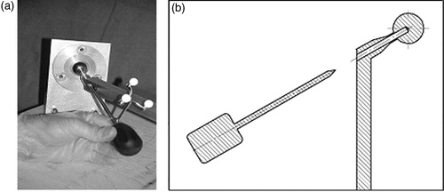
A hole 6 mm in diameter was drilled through the neck of the femur and part of the ball head, such that the center of the ball joint could be reached exactly with the pointer ( and ).
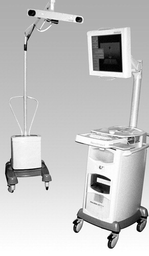
The Navitrack™ navigation system (distributed by Centerpulse AG, Zurich, Switzerland) () was used. This optical-based system uses Polaris® infrared cameras (Northern Digital, Inc., Waterloo, Ontario, Canada) and passive markers. The system is CT-less and uses pivoting of the femur to determine the rotational center of the hip joint. It does not require a marker on the pelvis. The system requires 14 different points to determine the center of rotation. During acquisition of each point (which takes approximately 5 seconds), the femur and its rigid body must be kept still.
Figure 3. The Navitrack navigation system used in the study. An opto-electronic infrared camera tracks the passive rigid bodies attached to the femur and pointer (www.centerpulse.com).
After referencing the femur, a schematic description of the femur and hip joint is displayed on the screen. A center point characterizes the rotational center with two concentric circles showing the deviation from the true rotational center. At the site of the knee, the transepicondylar axis is shown perpendicular to the mechanical axis ().
Figure 4. (a) Screenshot after registration of the transepicondylar line and rotational center of the hip. The schematic model of the femur is seen in four views (there are two sagittal views). (b) The same screenshot as in (a) but with an inserted pointer. [A color version of this figure is available in the online edition.]
![Figure 4. (a) Screenshot after registration of the transepicondylar line and rotational center of the hip. The schematic model of the femur is seen in four views (there are two sagittal views). (b) The same screenshot as in (a) but with an inserted pointer. [A color version of this figure is available in the online edition.]](/cms/asset/a2e2b737-be81-443c-aef4-a7ab58205ac3/icsu_a_122842_f0004_b.jpg)
As in our mechanical hip model, we were able to position the tip of the optically tracked pointer at the real rotational center of the hip joint, thereby verifying its virtual illustration on the screen at the same time (). With the help of this illustration, a scoring method was developed to describe the position: 1 = tip in center; 2 = tip in inner circle; and 3 = tip in outer circle ().
Figure 5. A detail from : The rotational center of the hip joint is surrounded by two concentric rings. The actual position of the pointer tip was validated by a scoring system in which the center received a score of 1, the inner ring a score of 2, and the outer ring a score of 3. When the actual position of the tip did not coincide with the measured one, the tip was displayed in one of the external rings. [A color version of this figure is available in the online edition.]
![Figure 5. A detail from Figure 4a: The rotational center of the hip joint is surrounded by two concentric rings. The actual position of the pointer tip was validated by a scoring system in which the center received a score of 1, the inner ring a score of 2, and the outer ring a score of 3. When the actual position of the tip did not coincide with the measured one, the tip was displayed in one of the external rings. [A color version of this figure is available in the online edition.]](/cms/asset/2404a479-19af-4aa9-982b-a8f2a60d17d9/icsu_a_122842_f0005_b.jpg)
In the first part of the study, three different scales of ROM of the hip joint were defined: good mobility (series I), fair mobility (series II), and poor mobility (series III) (see and ). For each of these series, the registration process was performed seven times.
Figure 6. Summary of the assessed ROM values for series I to V. Series I (dark green) was realized without extension lack. For series II (dark red) and series III (medium green), an extension lack of 10° and 20°, respectively, was realized. The light red and light green triangles illustrate the dot pitches of 8.7 cm and 4.4 cm, respectively. [A color version of this figure is available in the online edition.]
![Figure 6. Summary of the assessed ROM values for series I to V. Series I (dark green) was realized without extension lack. For series II (dark red) and series III (medium green), an extension lack of 10° and 20°, respectively, was realized. The light red and light green triangles illustrate the dot pitches of 8.7 cm and 4.4 cm, respectively. [A color version of this figure is available in the online edition.]](/cms/asset/04237394-a60d-4533-80cf-1a79970c1d9c/icsu_a_122842_f0006_b.jpg)
Table I. Range of motion (ROM).
In the second part of the study, the resolution of the system was to be determined. For this purpose we defined and adjusted the corners of a triangle with side lengths of 8.7 cm (series IV) and 4.4 cm (series V), respectively. In each of these series, the registration process was performed five times.
After each registration process (series I to V), the tip of the pointer was positioned in the center of the ball head, and its displayed position on the screen (real position of the rotational center) relative to the center point shown (computed position) was recorded.
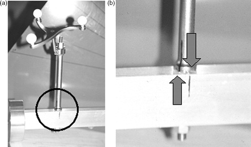
In the third part of the study, the rigid body was rotated around its axis by 45° in one pass and 22.5° in a second pass (). This procedure described the situation of a rigid body that is either mounted with insufficient rigidity or is manipulated.
Figure 7. (a) The rigid body is firmly attached to the femur by a borehole. (b) Magnification of the marked area in (a). The arrows mark the contortion of 22.5°.
Statistics
Statistic analysis was performed using SAS (“genmod” procedure). Series I, II and III and series IV and V were compared. Coronal and sagittal views were considered. A level of significance of 5% was assumed.
Results
In none of the trials was the tip of the pointer outside the circles. The mean values of the results are compiled in . No significant differences could be determined between series I and II, I and III, or II and III. A significant difference (p = 0.0019) was found between series IV and V, and also in the planes (p = 0.0098).
Table II. Results of series I to V.
It was found that a dependency exists when the results of all views (coronal, sagittal and axial) were assessed. Therefore, only the coronal and sagittal views were considered.
The rotation of the rigid body by 45° and then 22.5° was detected by the system and led to a rejection of the registration process.
Discussion
Experimental setup
A test bed with an exact center of rotation in a ball joint was realized. Using this test bed, it was possible to exactly assess the algorithm used by the CT-less navigation system to compute the rotational center of the hip joint.
The main challenge of such an evaluation is to transfer the virtually determined position of the hip and its center of rotation to reality and vice versa, thereby verifying it. The presented experimental setup proved the possibility of placing the pointer in the actual center of rotation. In addition, the display of the virtual center with surrounding concentric circles on the screen enabled results to be evaluated by means of a numerical score.
The constructively determined ROM of the model does not reach that of a healthy hip joint, but is sufficient to simulate the situation during surgery following the application of sterile bandages. The different spatial positions of the femur and its rigid body, which were adjusted using gauges, could be held still. The system takes approximately 5 seconds to save the coordinates of the rigid body, so the procedure is a static determination of the discrete points. This means that it makes no difference whether the points are reached in a translatoric or a rotatoric way. For this reason, in this experimental setup, we abstained from simulating the rotation of the femur in the hip joint.
Study design (limited mobility) and clinical relevance of the limitations
The clinical question that led to the present study was whether a patient with an ipsilateral hip osteoarthritis can be provided with an artificial knee joint using a CT-less navigation system Citation[2]. Concerns exist that one cannot be sure whether an arthritis-determined limitation of ROM in the hip joint allows accurate location of the rotational center of the hip. For this reason, different ranges of motion were defined. The diminution of the ROM was oriented towards pathological anatomical conditions. In particular, an extension lack could be simulated ().
A percentage of the enclosed ROM was used to describe the different limitations (see ). These declarations do not refer to the physiological ROM of a healthy hip joint. In fact, 100% corresponds to the initial situation of the study. Further percentages may be derived from this initial situation.
Results
As a result of the study, we conclude that the algorithm employed is capable of accurately computing the rotational center of the hip joint, even under restrictions such as a limited ROM (especially extension lack). The mechanical axis of the lower limb runs through the rotational center of the hip joint, and an artificial knee joint is aligned with this axis. When the center of rotation of the hip joint could not be determined correctly nor met in reality, malpositioning of the artificial knee joint had to be estimated. The consequences would be limited mobility of the artificial knee joint and reduced implant lifetime due to excessive wear. The results of this study show that a reduction of the ROM in the ipsilateral hip joint does not preclude the use of the evaluated CT-less navigation system when implanting a total knee prosthesis.
The evaluated system requires no pelvic marker when determining the center of rotation. The experimental setup also works without a rigid body in this area. Due to the technical design, in particular, such movements did not occur and could not be simulated. Thus, the above conclusion must be modified to the extent that a limitation in the mobility of the hip joint has no influence on the accuracy of the determination of the hip joint as long as the pelvis is not moved. The surgeon should obtain an idea of the range of motion of the hip joint before surgery, and take this into consideration when performing the pivoting under sterile draped conditions. Thus, a correct registration may be obtained under these circumstances. Krackow et al. Citation[2] also demand a stabilized pelvis during the registration maneuver, although they require a freely movable hip joint.
Only results in the coronal and sagittal views were analyzed, though the navigation system also displays an axial view on the screen. During statistical analysis, a dependency was found between the results. As the spatial location of a point is adequately determined by two orthogonal planes, the third view was deemed redundant and was not considered for further evaluation.
Minimum distance between spatial points
The distributor of the navigation system recommends a spatial distance of at least 10 cm between the registration points. One might therefore assume that, with less than a critical distance between points, the system will no longer be able to determine the center of rotation with sufficient accuracy. For technical reasons, a distance of 10 cm could not be set exactly. However, in the presented setup an angle of 10° between two spatial points led to a distance of 8.7 cm between the two positions of the rigid body. Bisecting this angle leads to a distance of 4.4 cm. Thus, we were able to approximate the 10 cm value and roughly bisect it. The results of series IV and V show that this bisection leads to a significantly degraded result. We therefore consider the critical distance for the spatial resolution of the systems to lie approximately between 4.4 and 8.7 cm ().
Table III. Spatial distances between points.
Rigid body
In the third part of the study, the rigid body was first rotated by 45° and then by 22.5° around its longitudinal axis. The system's reaction required a restart of the registration process. Apparently, the system offers a certain degree of security because the rotation of the rigid body would have a negative effect on the determination of the center of rotation of the hip joint.
Comparison with other studies
Several studies have been performed to rate the accuracy of CT-less navigation systems in determining the rotational center of the hip joint Citation[2], Citation[5], Citation[6]. Some of them used cadavers and equated the center of the femoral head with the mechanical center of rotation Citation[2], Citation[5]. Here, the assessment of the individual anatomy of the joint and geometrical inaccuracies that occur when digitizing the joint's surface had an impact on the results. We therefore consider that our approach to testing the algorithm used by the system to compute the center of rotation delivers more accurate results because the aforementioned disturbing factors are avoided. However, we were unable to simulate movements of the pelvis as accomplished by Stindel et al. Citation[6].
Conclusion
We were able to build an experimental setup to analyze the algorithm used by a CT-less navigation system for total knee replacement to determine the rotational center of the hip joint. Limitation of the ROM, as might be expected when there is a coexistent osteoarthritis of the hip, for example, does not significantly influence the accuracy. Thus, a limited ROM of the ipsilateral hip joint cannot be viewed as a contraindication for TKA. However, the surgeon should be aware of the fact that the pivoting of the femur must be performed within the free ROM of the hip joint. The effect of a moving pelvis could not be determined with this model.
The critical distance for accuracy seems to be between approximately 4.4 and 8.7 cm, i.e., in compliance with the vendor's recommendation, a minimum distance of 10 cm should be maintained between spatial points.
To guarantee a safe and unimpeded operation, the rigid body must be firmly attached to the bone and must not be dislocated during the procedure.
References
- Pott P, Schwarz M. Robots, navigation, telesurgery: state of the art and market overview. Z Orthop Ihre Grenzgeb 2002; 140: 218–31
- Krackow K, Phillips M, Bayers-Thering M, Mihalko W. A new technique for determining proper mechanical axis alignment during total knee arthroplasty: progress toward computer-assisted TKA. Orthopaedics 1999; 22: 698–702
- Leenders T, Vandevelde D, Mahieu G, Nuyts R. Reduction in variability of acetabular cup abduction using computer assisted surgery: a prospective and randomized study. Comput Aided Surg 2002; 7: 99–106
- Jenny J, Boeri C. Computer-assisted implantation of total knee prostheses: a case-control comparative study with classical instrumentation. Comput Aided Surg 2001; 6: 217–20
- Castelli C, Gotti V, Barbieri F. TKR CT-less femoral head detection accuracy on cadavers. Proceedings of 3rd annual meeting of International Society for Computer Assisted Orthopaedic Surgery (CAOS-International), MarbellaSpain, June, 2003
- Stindel E, Gyl D, Briard J, Merloz P, Dubrana F, Lefevre C. Detection of the center of the hip in computer assisted TKA: an evaluation study of the accuracy and reproducibility of the Surgetics algorithm. Proceedings of 2nd Annual Meeting of International Society for Computer Assisted Orthopaedic Surgery (CAOS-International), Santa Fe, NM, June, 2002