Abstract
As endoscopic surgery has become a popular form of minimally invasive surgery, it increasingly requires useful imaging tools to help the surgeons perform safe and secure operations. Our navigation system provides surgeons with visual information by overlaying 3D wire frame models of tumor onto live images, as well as by displaying relative the positions of surgical tools and the target tumor. Such 3D wire frame models are generated from pre-operative CT/MR images with the help of a 3D surgical simulation software. Another important function of our system is real-time volume rendering of intra-operative MR images for the target tumor. This function allows surgeons to carefully observe the vicinity of the tumor regions to be removed, by rendering the sectional views with respect to the surgical tool position, so that surgical performance can be easily monitored during the operation. We tested this navigation system in more than 10 clinical operations and verified the effectiveness of the navigation and surgical performance.
Objective
Augmented reality (AR) technology has increasingly played an important role in computer-aided surgery, especially in neurosurgery, which requires surgeons to perform secure and reliable surgical operations. For surgical navigation, Gering et al. Citation[1] developed a visualization system that overlays 3D surface models of tumors onto volume-rendered 3D MR images. Edwards et al. Citation[2] developed a navigation system that applied the AR technology to microscopic surgery. This system overlays the 3D surface models of tumors onto live video images from the microscope and helps surgeons to identify the position of the target and to increase surgical performance and safety.
Recent surgical operations using endoscopes have required a more advanced stage of minimally invasive surgery, which further reduces patients' physical damage, especially for endoscopic neurosurgery Citation[3]. When compared with microscope-based surgery, such operations greatly reduce patients' surgical damage, but at the same time require surgeons' high-level skills, owing to the limited view for observations and limited workspace for manipulations. The navigation techniques developed for microscopes are not sufficient for endoscopic surgery, because they do not directly provide useful information about the endoscope position and view orientation. This is essential for the surgeons to manipulate the endoscope to the target tumor by simultaneously observing its live video images. To solve such problems, we recently developed an augmented-reality-based navigation system for neurosurgery Citation[4–6]. The system overlays a wire frame model of the target and landmarks such as tumor, vessels and optic nerves onto live video images from the endoscope, to provide the surgeons with useful information about on-going surgical operations in real time. The system was tested in actual surgery more than 10 times and demonstrated its effectiveness and efficiency.
In a general surgical procedure, especially after tumor removal, the surgeons must verify whether any portions of tumor still remain in the vicinity of the target. To precisely observe the condition of the tumor and its vicinity, open MRI has been recently introduced into the operating theater Citation[7], Citation[8]. After most of the tumor is thought to be removed, surgeons must verify this by scanning the patient brain area intra-operatively with open MRI. If residual portions of tumor are observed, such portions need to be removed by way of updated intra-operative MR images. Unfortunately, conventional open MRI equipment does not display on-site volume-rendered images, which specifically and precisely correspond to the position and orientation of the endoscope; therefore, it is difficult for surgeons to promote endoscopic surgery based on the updated information of tissues after the surgical operation.
As this article will present, we developed a new system that effectively integrates intra-operative MRI monitoring to the aforementioned endoscopic AR navigation system. In our new system, open MR images are taken during the surgery, and registered with the endoscope frame so that the updated target tumor regions can be easily identified by the surgeons even after removing some portions of the tumor. This function therefore provides surgeons with verification of surgical performance and aids replanning of surgical operations. Furthermore, our system integrates many aspects of navigation technologies using (1) efficient image-based 3D modeling of human brain, (2) interactive surgical planning, (3) efficient 3D modeling of endoscopic optics, (4) precise calibration and registration techniques for augmented reality, and (5) fast volume-rendering techniques for open MRI monitoring. This system is proven to support secure and reliable surgery. We tested this system more than 10 times for surgeries of pituitary tumor removal and verified the effectiveness and efficiency.
In the following sections, we first describe the overall system concept and then explain the technical details of our AR-based navigation system, which contains 3D data construction and intra-operative navigation functions. Finally, experimental results from the actual clinical tests are reported.
Materials and methods
Overall system architecture
shows our system in a typical neurosurgical situation, where the surgeon performs endoscopic operations by looking at the navigation monitors. Our system provides surgeons with visually effective navigation functions, namely, overlay function and volume-rendering function. As shown in , the overlay function provides a capability of overlaying onto live endoscope video the 3D wire frame models of target organs generated from CT/MRI. It therefore helps surgeons to intuitively understand the relative position and distance from the current surgical tool position to the target, as well as the surface shape of the target organ within the endoscope view.
Figure 1. A typical endoscopic surgery situation for pituitary tumor using the navigation system.
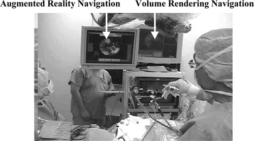
Figure 2. Overlay controller displays 3D wire frame models of target tumor along with anatomical landmarks on the endoscope live video. In the control window, the blue frame represents tumor, the green optic nerves, and the light blue internal carotid artery. Important to mention here is that the wire frame is displayed even outside the view field of the endoscope. [color image available online]
![Figure 2. Overlay controller displays 3D wire frame models of target tumor along with anatomical landmarks on the endoscope live video. In the control window, the blue frame represents tumor, the green optic nerves, and the light blue internal carotid artery. Important to mention here is that the wire frame is displayed even outside the view field of the endoscope. [color image available online]](/cms/asset/0896a31f-3c62-4da4-bbc8-dfea55d155cb/icsu_a_122921_f0002_b.jpg)
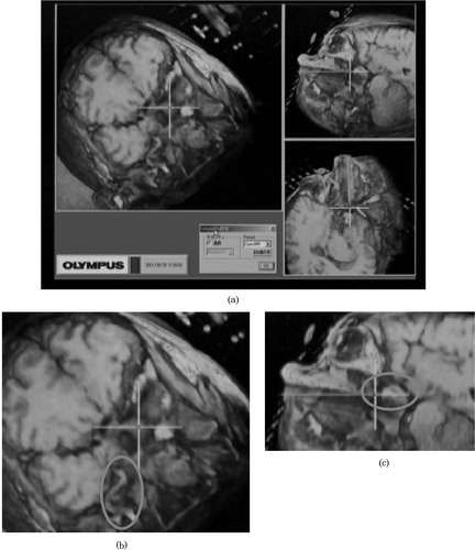
The volume-rendering function provides a capability of displaying various sectional images of 3D volumetric CT/MRI data. In particular, three orthogonal views are simultaneously displayed, including the sectional image perpendicular to the view direction of the endoscope, as shown in . This helps surgeons to comprehend the anatomical structure around the tumor easily and immediately.
Figure 3. (a) The volume-rendered sectional images generated from open MR data. The cross-hair represents the tip position of the endoscope. (b) The overlaid ellipse encloses the vessel around the tumor. (c) The overlaid ellipse encloses the remaining tumor.
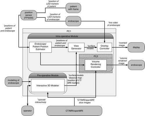
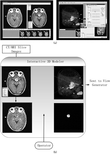
depicts the system architecture of our current system. Our system consists of a pre-operative module and an intra-operative module. The pre-operative module contains an interactive 3D modeler, which semi-automatically generates the 3D wire frames of the target tumor and landmark tissues from CT/MRI slices and also generates the distance map from the tip of the endoscope to the target tumor; these are necessary for navigation in the intra-operative module.
Figure 4. Overall architecture of our AR-based navigation system with open MRI monitoring capability.
First, the intra-operative module aligns the 3D pre-operative data with the patient head in the operating theatre. To accomplish this alignment, we use a FlashPoint 5000 (FP5000, Boulder Innovation Group, Inc., Bolder, CO), optical sensor and also a newly developed eyeglass-like registration frame with fiducial markers and infrared LED markers, which can be tracked in real time to compensate for the patient movement in the operating theater. The details of alignment will be described in a later section. The average error of the position and orientation estimation is 0.3 mm.
Secondly, the intra-operative module estimates the relative position and orientation between the endoscope and the patient during the operation. To attain this function, we attach reference registration frames with infrared LED markers, which are specially designed and mounted on both the endoscope and the patient. The FP5000 optical sensor measures the positions and orientations of both the endoscope and the patient by detecting the above individual LED marker positions in real time. These data are sent from the optical sensor to the intra-operative module to accomplish the real-time navigation.
By receiving these data, the intra-operative module displays two significant images; an overlaid image and a volume-rendered image. These two images are generated by the overlay controller and volume-rendering controller, respectively. In the overlay controller, 3D wire frame models made in the pre-operative module are overlaid onto the live endoscope video images as shown in . Note that wire frame models and live video images are registered with 1-mm accuracy. The overlay controller also displays other information useful for navigation. For example, the distance from the current endoscope tip position to the target tumor is shown with horizontal color bars in the top of the view window. In addition, three volume sections (axial, coronal and sagittal sections) of CT/MR images are shown in three corners of the view window, as shown in . In these volume sections, the current position and view direction of the endoscope in the CT/MRI frame are shown as bold lines of bright colors so that surgeons can easily understand the surgical actions.
The volume-rendering controller interacts with the overlay controller and the open MR imaging unit and generates the volume-rendered images in the window on the basis of the current endoscope position in real time. More specifically, three vertical sections of volumes with respect to the current endoscope position and orientation are rendered, as shown in . Note that the largest view is vertical to the endoscope direction. These rendering functions are applied to both pre-operative CT/MR images and intra-operative open MR images.
Surgeons freely control the endoscope position around the target tumor during the operation, so that they can easily identify the remaining tumor after removing some portions. In addition, three vertical views shown in the overlay window (axial, coronal and sagittal views) are also updated as the current open MR images are acquired. These volume-rendering functions therefore allow the surgeon to replan the subsequent surgical procedures and actions.
Technical details
This section describes the detailed functions of our navigation system. Our system has two special characteristics that differ from those of other navigation systems. The first characteristic is associated with a technique to acquire 3D data for navigation and the second a technique to effectively display the navigation information to surgeons. These two techniques are carried out in the pre-operative module and intra-operative module in our system, respectively.
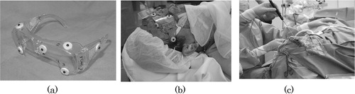
Before describing the details of the above two modules, we wish to introduce another important component that is essential to realize minimally invasive surgery—a specially designed eyeglass registration frame for brain surgery. The purpose of this registration frame is to accomplish an accurate alignment of the CT/MR images with a patient's head in the operating theater. shows the eyeglass registration frame. The frame is equipped with several fidicial markers, which are significantly detectable in both CT and MR images by an automatic computer program. In addition, a reference registration frame with LED markers can be directly attached to this eyeglass registration frame, the LED markers being used to estimate the position of the frame with respect to the endoscope to which a similar reference registration frame is attached. The frame is fixed to the patient with silicon rubber, as shown in , to fit the frame to the unique surface of the patient. It is also detachable after CT/MRI scans and is worn accurately during surgery. The silicon rubber maintain the shape of the unique surface of the patient's face.
Figure 5. This set of figures displays the registration equipment and procedures. (a) The reference registration frame with markers visible in CT/MR images, (b) the patient wearing the reference registration frame with silicon rubber and (c) a surgeon registering the position of markers just before surgery by stylus probe with LEDs in order to align the patient's head and CT/MRI slices.
Some other techniques of registration are also available for surgical navigations. One method is based on surface-matching, developed by Grimson et al. Citation[9], using a laser range scanner; however, it requires a large amount of computational power. Other conventional methods use
(1) screw markers that are invasively inserted into the skull so that the markers will not move during the surgery, or
(2) face markers that are flexibly attached to the skin of the patient's face; however, those lead to misalignment due to facial skin deformation.
Our eyeglass registration frame is, however, non-invasive, unlike screw markers, because it is simply placed on the patient's face. It is also not moved, unlike conventional face markers. The rigidity of the markers is ensured owing to the silicon rubber that is stuffed in the space between the frame and the patient's face, specifically on the patient's root of the nose and brow.
By measuring the positions of the fiducial markers in the CT/MR images, we can completely specify the relative position of both the tumor and critical tissues with respect to the patient's head. This frame therefore enables far less-invasive and more accurate surgery, because
(1) it is detachable and re-attachable before and after the CT/MRI scans, and
(2) it compensates for the patient's movement during the surgery with an additional LED reference registration frame attached directly to the eyeglass reference frame, as shown in .
Pre-operative procedures
The pre-operative procedure is a process of preparing 3D data for navigation, which is intra-operatively used to accomplish visual navigation functions. In this section, the pre-operative procedure will be explained according to . In preparation for the surgery, CT and MR images of a patient are first scanned. Using these images, doctors then generate a 3D surface model of the target tumor and landmark tissues and make an optimal surgical plan for a patient by simulating a prospective surgery.
Pre-operative CT/MR scanning
The purposes of the pre-operative CT/MR scanning are (1) to generate 3D models of the target tumor and landmark tissues along the surgical paths and (2) to reconstruct images in arbitrary directions associated with the endoscope position and orientation. We therefore acquire CT/MR scanning images as follows:
(1) Both CT and MR images are scanned before the surgery, because both the bones visible in the CT images and soft tissues visible in the MR images become significant landmarks for registration.
(2) The eyeglass registration frame discussed in the previous section is attached to the patient's head before the scans.
(3) The scanning resolution should be matched with the navigation accuracy—more specifically, the CT scanning condition is as good as 1 mm pitch, and the MR scanning condition for our navigation system is as good as 1 mm pitch, axial, T1.
(4) The scanned images are transferred, in a DICOM format, from the modality to the interactive 3D modeler to generate the 3D models of tumors and landmarks in a matched form.
Interactive 3D modeling: Surface models and distance map
To navigate surgeons in the operating theater, important tissues such as the tumor and landmarks must be modeled from original CT/MR scanned images. The interactive 3D modeler contributes to this procedure with minimal interaction with the doctors. The interactive 3D modeler produces the 3D wire frame models of the tumor and landmarks, distance information on the tumor and fiducial marker information in CT/MR images.
After the CT/MR scans, the image data are transferred to the pre-operative module. Doctors use the interactive 3D modeler to assign the regions of interest (ROIs) semi-automatically. We have learned that the conventional thresholding techniques for generating ROIs are not satisfactory, because the contrast of the tissues that contain the carotid artery, tumor and optic nerve vary from region to region even in the same organs. In the interactive 3D modeler, we developed a new edge-based and region-based semi-auto segmentation software with a human-friendly interface. This modeler initially segments representative CT/MR slice images out of the entire set of the slice images in an automated mode and then asks the operators to confirm or correct the results manually. The modeler then generates the 3D volumetric regions (ROIs) for the tumor and landmark tissues by propagating and interpolating the segmentation results obtained from the representative slice images, as shown in . Using this editor, the doctors' load and time for assigning ROI, are greatly reduced.
Figure 6. Interactive 3D modeler. (a) Examples of segmentation and visualization windows. (b) Schematic procedures for interactive 3D modeling.
Once the 3D-ROIs are obtained, the 3D surface models are also generated. They will be mainly used as wire frames for superimposition in the intra-operative procedures.
These 3D models are also used for a pre-operative simulation. Doctors check the position and shape of the target tumor, as well as the relative locations of the landmarks, such as the internal carotid artery and optic nerve, with respect to the target tumor, by observing the 3D models carefully.
In addition to the overlaid images and three-axial sectional CT/MR slice images, the system displays the distance map from the tip of an endoscope to the target tumor. The distance is indicated by the length of the bar in the top of the navigation window. Also, the color of the wire frame of the tumor changes according to distance, on the basis of the distance map calculated pre-operatively. Such visualization helps the surgeon to quickly understand how to manipulate the endoscope toward the destination at the target tumor. For example, if the distance is over 1 mm, the wire frame color of the tumor is blue. When the tip of the endoscope approaches to within 1 mm, the tumor color changes to yellow. Finally, when the tip reaches the tumor, the color changes to red.
The distance map generation is straightforward in the pre-operative mode. The 3D modeler prepares a volumetric distance map array with resolution of 1 mm quantization which includes the entire volume of the CT/MR scans. For each voxel inside the volumetric distance map array, the 3D modeler automatically and preoperatively computes the smallest Euclidean distance from the voxel to the target tumor 3D-ROIs. This distance map array is sent to the view generator and is used as the quantized distance from the endoscope tip to the tumor in the operation; therefore, the information on distance is promptly displayed during an actual navigation.
Modeling of the endoscope
In addition to 3D modeling of the tumor and landmarks described in the previous section, we also need to estimate the endoscope view characterization (endoscope calibration) to accurately overlay the 3D wire frame model onto the live video. More specifically, the aim of endoscope calibration is to estimate two sets of parameters: (1) the optical parameters of the endoscope and (2) fixed parameters associated with the relative pose between the endoscope tip and the reference registration frame attached to the endoscope.
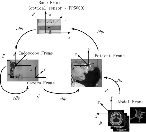
shows the coordinate frames used in our system. By calibration, we estimate the fixed coordinate frame transformations between various coordinate systems except the transformation between the endoscope frame and the patient frame. This transformation in the intra-operative mode is estimated in real time by the optical sensor FP5000, whose base coordinate is represented by B, to cancel out the patient's movement in the operating theater.
Figure 7. Coordinate frames used in our navigation system. The registration process requires the estimation of transformations between coordinate frames.
One key point in the calibration procedure is that we accurately model the lens distortion of the endoscope to register 3D wire frame models of tumor and landmarks with the live endoscope video image even in the peripheral areas of the endoscope views. Our calibration guarantees an accuracy of 0.3 pixels for lens distortion modeling and an accuracy of 1.0 mm for co-ordinate transformations. The details of the calibration procedures are described in Appendix A.
Intra-operative procedures
The intra-operative procedure assists surgeons by offering secure and efficient surgical environments. The assistance is realized by two functions: overlay function and volume rendering function.
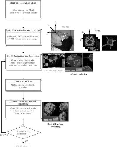
The intra-operative module overlays the wire frame models of the patient's head on the live endoscope view frame by measuring in real time the position of both the endoscope and the patient's head in the operating theater. It also displays 3D volume-rendered images of intra-operative MRI. The volume-rendered sectional image is, of course, generated on the basis of the current endoscope position. The image is used to confirm the condition of the remaining tumor. Steps 3–5 in show the procedure for the volume-rendering function.
Figure 8. Actual steps in the overall navigation.
Endoscope/patient position estimation
The endoscope/patient position estimator in calculates the endoscope position with respect to the patient's head. Registration reference frames with LED markers are attached to both the endoscope and the patient's head (). The optical sensor (FP5000) keeps track of the positions of the LED markers in real time and sends the position data to the endoscope/patient position estimator. The endoscope/patient position estimator then estimates the endoscope position with respect to the patient's head in the form of transformation matrices, as shown in Appendix A. The mean error for estimating relative positions using the optical sensor (FP5000) is approximately 0.3 mm.
Figure 9. The LED markers are used to estimate the positions and orientations of the patient's head, the endoscope and the stylus probe. (a) Eyeglass registration frame; (b) endoscope registration frame; (c) LEDs on probe.
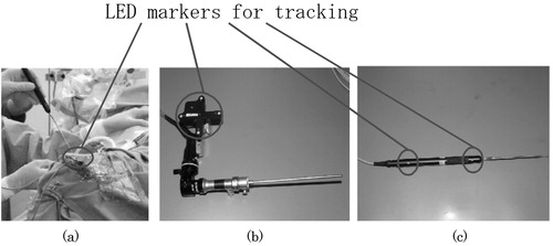
Figure 10. Our AR navigation system also allows surgeons to use endoscopes of side view 30°, for which the view directions of the endoscope are overlaid onto the three sectional subwindows. This functionality greatly helps the surgeons understand the endoscopic surgery.
View generation and overlay control
As shown in , the view generator creates the wire frame models of the tumor and landmark tissues aligned to the view frame of the endoscope.
Once the view generator receives the endoscope position with respect to the patient's head, it creates the wire frames of the tumor and landmark tissues, which are aligned to the live endoscope view. As we have mentioned in the previous section, we model the endoscope distortion optics with an appropriate accuracy; the wire frames are overlaid with distortion onto the live endoscope image so that the image augmentation can be perfectly attained. shows the precise overlay dealing with endoscope lens distortion. We also notice that wire frame models of the tumor and landmarks are also projected onto the outside of the limited endoscope view. This projection significantly extends the surgical view space, and therefore helps the surgeons to intuitively understand critical tissues around the operation area so that they can promote safe and secure endoscopic surgery.
The overlay controller contains a frame grabber and overlays wire frame models sent from the view generator onto live endoscope video precisely, then sends the overlaid video to the display.
Navigation using overlay function in the operating theater
Our AR-based navigation is an integration of useful visual aids such that the surgeons can visually and intuitively understand the on-going surgical status by simply looking at one monitor display. As shown in , and 10, several windows pop up when the navigation function starts. The windows include a live video from the endoscope in the center, which is overlaid with the wire frames of the tumor and landmarks when the surgeons wish to display them. Important to mention here is that the wire frames of the tumor and landmarks can be displayed even if they are occluded with blood and liquid or are outside the limited endoscope views. Another visual aid for navigation is the color bar at the top of the monitor display which represents the distance from the endoscope tip to the target tumor, as we have already discussed. In addition, three sectional CT/MR images (axial, coronal and sagittal), which are pre-operatively prepared, can be displayed when the surgeons wish to confirm the position and orientation of the endoscope tip. Note that open MRI can also be used in these windows. In general, a single sectional image is taken by X-ray fluoroscopy (C-arm) whenever the examination of the position of the endoscope is needed during the operation.
Our navigation system has the capability of displaying in realtime the position of the endoscope in relation to anatomical landmarks of interest such as bone structure from CT images and tumors, vessels and nerves from MRI. The landmarks are displayed either in three sectional windows or in the main window along with live video images.
The system therefore reduces the number of C-arm examinations during surgery thereby reducing the exposure to radiation both for patients and surgeons. Also, the navigation system can be used without having to change the conventional configurations and procedures for brain surgery.
MRI volume rendering
AR-based navigation described in the previous section is efficient and effective for guiding the endoscope to the target tumor. Once the surgeon starts removing/cutting the tumor physically, however, the volumetric shape of the tumor obviously changes, and therefore, the previous 3D model of the tumor no longer represents its current shape.
Open MR images lead us to a good solution to this problem, as volumetric images can be taken intra-operatively. This capability greatly helps surgeons to confirm the remaining tumor and to replan subsequent surgical operations by updating the current anatomical structure of the patient's head during the surgery.
We integrated the AR-based navigation and the open MRI functionality to achieve more reliable and secure surgery. shows the procedure to efficiently apply the volume-rendering function during the surgery.
The following contains the actual steps for the open MRI examination: When surgeons have removed/cut a large portion of tumor, they stop operations and first scan the open MRI of the patient's head. Then, the scanned data are sent from the open MRI to the navigation system, and the positions of the markers are identified in the slice images of the open MRI using the interactive 3D modeler. Then alignment between the patient's head and open MRI slices is automatically assured, because the eyeglass registration frame remains in the same relative position as it was with respect to the patient's head. The volume-rendering controller calculates a cross-sectional image perpendicular to the endoscope, and also two sectional images that contain the axis of the endoscope.
These sectional images help the surgeons visually observe the remaining part of the target tissue from arbitrary positions and directions by moving the endoscope by hand, whereas the conventional axial, coronal and sagittal images only allow the surgeons to observe from limited and fixed directions. The three sectional images based on our volume rendering function are displayed synchronously with the AR overlaid video image.
In our experiments, we used the open MRI AIRIS II (0.3T, Hitachi Medical Corporation, Tokyo, Japan) to obtain real-time information during the operation, and an image processing board VolumePro500 (TERARECON, Inc., San Mateo, CA) for volume rendering.
Results
We first tested our navigation system using a phantom for the feasibility and accuracy evaluations. We then tested the system clinically on real patients. The phantom was used to evaluate our system technically, and we verified that the accumulated registration error of our system is less than 2 mm.
After the phantom test, our system was tested 10 times in actual endonasal surgery for pituitary tumor removal at Tokyo Women's Medical University Hospital. The ages of patients ranged from 28 to 79 (male: 2 cases; female: 8 cases). The overall time required for pre-operative procedures, such as CT/MRI scans, ROI-assigning, 3D wire frame generation, and distance map generation, was less than 3 h. The surgery time for the intra-operative procedures including open MRI was typically 5 h. The most difficult case for surgery (the tumor was as large as 30 mm) required 8 h, which involved open MRI monitoring. In four cases, the navigation system was used without C-arm and with open MRI. The registration procedures take only 30 s, approximately, and the registration accuracy is less than 1.5 mm. The accuracy of the overlaid video image is kept adequate to accomplish the surgery.
Discussion
From the clinical point of view, doctors determining that the system possesses three outstanding advantages over conventional surgery navigation systems. The first advantage is that surgeries can be accomplished without X-ray fluoroscopy (C-arm), because our navigation displays three sectional images (axial, sagittal and coronal) and the overlaid image of the endoscope. The second advantage is observation and replanning during intra-operative procedures, because the open MRI and the volume-rendered sectional images can intuitively display the condition of tissues after the portions of tumor are removed. The third advantage is the usability and reliability of the navigation. Our intra-operative procedures are simple because of the eyeglass registration frame.
From the technical point of view, our navigation system has three characteristics: (1) an overlay function, (2) a volume-rendering function and (3) a registration function using the eyeglass registration frame.
Each of the three functions obviously contributes to the establishment of minimally invasive surgery. However, the combination of these functions constitutes a more powerful and more efficient tool to assist surgery.
The overlay function and the volume-rendering function complement each other in the following two aspects: First, the overlay function provides surgeons with information from the endoscope as a view frame. In contrast, the volume rendering function provides different information from the overlay function, i.e., the sectional images which correspond to the current position of the endoscope tip and axis. Secondly, the overlay function assists both planning pre-operatively and promotion of surgical procedures before removing large portions of tumor, whereas the volume rendering helps to confirm the remaining tumor and to replan after tissue-deformation due to tumor removal. The eyeglass registration frame provides surgeons with adequate registration accuracy of 1 mm and simple surgical procedures and contributes to safe and secure surgery. From these points of view, surgical procedures which combine these three functions lead to one of the best solutions among the current technologies for endonasal transsphenoidal operations to treat pituitary tumors.
On the basis of characteristics described earlier, the eyeglass registration frame significantly contributes to endonasal transsphenoidal operations. To apply this registration frame to other neurosurgical operations, it is essential to develop a new registration frame which will be suitable for the operations, for example, in the sense of simple use, compact size and accuracy.
Currently, endonasal transsphenoidal operations have become a popular procedure. In our clinical tests for endonasal transsphenoidal operations, brain-shift is not significant in the trajectory of the endoscope. Moreover, the influence of brain-shift in our system is reduced by evaluating and verifying the surgical performance using intra-operative MR. However, in order to realize surgical navigation in relation to other surgical procedures, we must evaluate the brain-shift more carefully. In these cases, it is essential to improve the accuracy and functionality of the overlay function dealing with real-time deformation-based 3D modeling of tissues.
References
- Gering D T, Nabavi A, Kikinis R, Hata N, O'Donnell L, Grimson WEL, Jolesz F A, Black P M, Wells W M. III. An integrated visualization system for surgical planning and guidance using image fusion and an open MR. J Magn Reson Imag. 2001; 13: 967–975
- Edwards P J, King A P, Maurer C R, Jr, de Cunha D A, Hawkes D J, Hill D L.G, Gaston R P, Fenlon M R, Jusczyzck A, Strong A J, Chandler C L, Gleeson M J. Design and evaluation of a system for microscope-assisted guided interventions (MAGI). IEEE Trans Med Imag. 2000; 19(11)1082–1093
- Taylor R H, Lavaleé S, Burdea G C, Mösges R. Computer-Integrated Surgery. MIT Press. 1996, editors.
- Akatsuka Y, Shibasaki T, Saito A, Kosaka A, Matsuzaki H, Asano T, Furuhashi Y. Navigation System for Neurosurgery with PC platform. Proceedings of Medicine Meets Virtual Reality. 2000; 10–16
- Akatsuka Y, Kawamata T, Fujii M, Furuhashi Y, Saito A, Shibasaki T, Iseki H, Hori T. AR Navigation System for Neurosurgery. Medical Image Computing and Computer-Assisted Intervention Proceedings. 2000; 833–838
- Kawamata T, Iseki H, Shibasaki T, Hori T. Endoscopic augmented reality navigation system for edonasal transphenoidal surgery to treat pituitary tumors – technical note. Neurosurgery. 2002; 50(6)1393–1397
- Pergolizzi R S, Jr, Nabavi A, Schwartz R B, Hsu L, Wong T Z, Martin C, Black P M, Jolesz F A. Intra-operative mr guidance during trans-sphenoidal pituitary resection: Preliminary results. J Magn Reson Imag. 2001; 13: 136–141
- Jolesz F A, Nabavi A, Kikinis R. Integration of interventional MRI with computer-assisted surgery. J Magn Reson Imag. 2001; 13: 69–77
- Grimson W E.L, Ettinger G J, White S J, Lozano-Perez T, Wells W M. III, Kikinis R. An automatic registration method for frameless stereotaxy, image guided surgery, and enhanced reality visualization. IEEE Trans Med Imag. 1996; 15(2)129–140
- Weng J, Cohen P, Herniou M. Camera calibration with distortion models and accuracy evaluation. IEEE Trans Pattern Anal Mach Intell. 1992; 14(10)965–980
- Haralick R, Shapiro L. Computer and Robot Vision. Addison Wesley. 1992; 2
Appendix A
This appendix describes techniques for camera calibration and registration necessary for the AR-based navigation.
(1) Coordinate transformation
First, we define the following coordinate frames in our navigation architecture, as shown in .
(a) Model frame (M): computer-generated coordinate frame associated with CT/MR slice images.
(b) Camera frame (C): endoscope camera coordinate frame associated with endoscope viewing functions.
(c) Patient frame (P): coordinate frame associated with the patient, which is defined in the operating theater.
(d) Endoscope frame (E): coordinate frame associated with the endoscope registration frame, which is mounted on the endoscope.
(e) Base frame (B): coordinate frame associated with the FP5000 optical sensor, which measures both the positions of the reference registration frame and the endoscope registration frame.
Once we define the aforementioned coordinate frames, we can also define the coordinate transformations between any of the two coordinate frames described earlier. For example, the FP5000 optical sensor can compute the transformations of six degrees of freedom as (i) a transformation from the base frame (B) to the endoscope frame (E) and (ii) a transformation from the base frame (B) to the patient's head frame (P). Let E RB and E TB be the rotation matrix and the translation vector associated with the transformation from B to E. Then, we can also define the homogeneous transformation matrix (4 × 4) from ERB and ETB with respect to the 3D points (xB, yB, zB) in frame B and the corresponding 3D points (xE, yE, zE) in frame E
From such individual transformation, we can also compute various transformations by combining the individual transformations. For example, the transformation from the model frame M to the endoscope frame E can be computed bywhich plays an important role in producing the computer-generated wire frame of the tumor overlaid onto the endoscope live image when the tumor model is obtained in the CT/MRI.
(2) Optical modeling and calibration of endoscopes
The objective of the optical modeling and calibration of endoscopes is to estimate various parameters necessary for producing computer-generated wire frame models of the tumor when we are given the coordinate transformations used in equation (A2). More specifically, we define intrinsic camera parameters for endoscope views such as magnification factors, image center, and lens distortion, as well as extrinsic camera parameters for the endoscope associated with the transformation CHE. This procedure is known as the camera calibration procedure described, for example, in the paper by Weng et al. Citation[10]. Here, we briefly describe the optical modeling and calibration of the endoscope. The entire endoscope optical model is given by the following equations of three steps for a given 3D point (xE, yE, zE) in frame E and distorted image point (u′, v′) in the endoscope view. In these equations, (αu, αv) represent magnification factors in the endoscope horizontal and vertical view directions; (u0, v0) the image center of the endoscope horizontal and vertical view; (k1, g1, g2, g3, g4) lens distortion parameters in the endoscope view, rotational matrix CRE = (rij) and translational vector CTE = (tx, ty, tz):
(a) Coordinate transformation CHE and endoscope view normalization:
(b) Lens modeling of radial and tangential distortion:
(c) Inverse-normalization to actual endoscope view
In total, 15-dimensional parameterneeds to be estimated, where (ϕx, ϕy, ϕz) represents the rotation angles associated with the rotation matrix CRE = (rij).
In the actual calibration procedure, we use a special calibration board which includes known 3D markers (xE, yE, zE) in frame E and take snapshots of the calibration board to obtain the projected 2D image points (u′, v′). We then estimate the modeling parameter p by using Weng's method Citation[10].
(3) Position estimation of endoscope tip
The position of the endoscope tip with respect to the endoscope frame is needed to display the distance map from the current endoscope tip position to the tumor. This estimation is done in conjunction with the camera calibration procedure described above. More precisely, we use the sensor probe equipped with the FP5000 optical sensor to directly measure the tip position (xB, yB, zB) with respect to frame B, as well as to directly measure the coordinate transformation from frame B to E (EHB). Once these values are obtained, the position of the endoscope tip (xE, yE, zE) is computed by Equation (A1).
(4) Registration
Another important problem to discuss here is an actual registration procedure for the patient head and the CT/MRI slice model. More specifically, we need to estimate the coordinate transformation from the CT/MRI model frame (M) to the patient frame (P).
As we have discussed in the previous sections, the patient mounts the eyeglass registration frame when his/her head is scanned by CT/MRI. The eyeglass registration frame is equipped with CT/MRI fiducial markers whose positions in the eyeglass registration frame are known. The positions of CT/MRI markers in the images are also measured in a semi-automatic way, using the interactive 3D modeler. Let be the CT/MRI marker position of marker k in the CT/MRI model frame M, and let
be the corresponding position of the same marker k in the patient frame P. What we need to estimate here is the transformation from frame M to P, given m markers (indexed by k = 1, 2, …, m). Mathematically, this relation is formalized by
where PRM and PTM are the rotation matrix and the translation vector of the transformation from frame M to P for m marker correspondences. The method of estimating PRM and PTM are well described, for example, in Weng et al. Citation[10] or Haralick and Shapiro Citation[11].
(5) Generation of computer-generated wire frame model
With the coordinate transformation from sensor frame B to patient frame P and the coordinate transformation from sensor frame B to endoscope frame E, it is easy to generate the wire frame model. In our current implementation, wire frame models of tumors consist of line segments, and segments are specified by two endpoints. Let (xM, yM, zM) be one of the endpoints of the line segments. During the operation, the positions and orientations of the patient's head and the endoscope registration frame are measured by the FP5000 optical sensor in real time. More specifically, the coordinate transformations from frame B to P (PHB) and frame B to E (EHB) are simultaneously obtained. The task here is how to compute the endoscope view position (u′, v′) corresponding to the tumor wire frame point (xM, yM, zM). We take the following two main steps:
1) Compute the transformation from frame M to C (CHM) by Equation (A2)
2) For each 3D tumor wire frame point (xM, yM, zM),
2–1) compute the corresponding 3D camera frame point (xC, yC, zC) by
2–2) compute the endoscope view point (u′, v′) with distortion by Equations (A3)–(A5).
All are simple and are suitable for real-time computations.