Abstract
Fluoroscopy is the most common tool for the intraoperative control of long-bone fracture reduction. Limitations of this technology include high radiation exposure for the patient and the surgical team, limited visual field, distorted images, and cumbersome verification of image updating. Fluoroscopy-based navigation systems partially address these limitations by allowing fluoroscopic images to be used for real-time surgical localization and instrument tracking. Existing fluoroscopy-based navigation systems are still limited as far as the virtual representation of true surgical reality is concerned. This article, for the first time, presents a reality-enhanced virtual fluoroscopy with radiation-free updates of in situ surgical fluoroscopic images to control metaphyseal fracture reduction. A virtual fluoroscopy is created using the projection properties of the fluoroscope; it allows the display of detailed three-dimensional (3D) geometric models of surgical tools and implants superimposed on the X-ray images. Starting from multiple registered fluoroscopy images, a virtual 3D cylinder model for each principal bone fragment is constructed. This spatial cylinder model not only supplies a 3D image of the fracture, but also allows effective fragment projection recovery from the fluoroscopic images and enables radiation-free updates of in situ surgical fluoroscopic images by non-linear interpolation and warping algorithms. Initial clinical experience was gained during four tibia fracture fixations that were treated by LISS (Less Invasive Stabilization System) osteosynthesis. In the cases operated on, after primary image acquisition, the image intensifier was replaced by the virtual reality system. In all cases, the procedure including fracture reduction and LISS osteosynthesis was performed entirely in virtual reality. A significant disadvantage was the unfamiliar operation of this prototype software and the need for an additional operator for the navigation system.
Introduction
The fluoroscope, also known as a C-arm, is the most important and commonly used imaging system in traumatology and orthopaedic surgery. It is an important instrument for intraoperative diagnostics, for the precise visualization of achieved fracture reduction, for checking the position of surgical instruments such as drill bits, and for the verification of the correct placement of osteosynthesis material and other implants. In recent decades, traumatological techniques have undergone considerable modifications. Though in the past fractures used to be exposed to a considerable extent and stabilized with accordingly sized plates, it is now generally agreed that the technique of minimally invasive osteosynthesis yields superior results. Minimization of the skin incision and reduction of the induced soft tissue damage result in a number of considerable advantages for the patient, including both the cosmetic result and improvements in function and healing time Citation[1], Citation[2].
One of the difficulties with minimally invasive techniques in fracture treatment is caused by the absence of direct visualization of the implant and the accuracy of the achieved reduction. As a consequence, the fluoroscope is used more intensively during modern surgical techniques. For that reason, both patient and surgical staff are exposed to high radiation doses Citation[3]. In addition, C-arm imaging suffers from certain restrictions. Each image is a two-dimensional projected representation. Furthermore, only one fluoroscope is usually available, that is, only one projection may be visualized at a time, requiring continuous repositioning of the C-arm. The surgeon must position the implant in one plane and use additional images in other planes for trial-and-error placement of the implant. During image acquisition, the device must be placed in the operation field, potentially hindering surgical treatment. The integration of conventional fluoroscopes into computer-assisted navigation systems has been established as a means to overcome certain of these drawbacks and to provide solutions or elements of solutions to the described problems Citation[4–7].
Computer-assisted surgical procedures are rapidly evolving in traumatology and are currently crossing the border between experimental scientific approaches and routine clinical applications. The principle is based on the linking of image information and intraoperatively tracked surgical instrument or implant positions. Preoperatively acquired data such as that from computed tomography (CT) or magnetic resonance imaging (MRI) may be suitable as image information, but so may images taken intraoperatively using conventional C-arm technology Citation[4],Citation[6–9].
Although a number of authors have reported excellent experiences with currently existing systems for virtual fluoroscopy, two disadvantages of these devices can be identified during routine clinical use. The purely two-dimensional representations of surgical tools represent the tracked objects in a rather abstract way. Moreover, changes in the bony anatomy due to fracture reduction or osteotomy can only be analyzed by the re-acquisition of C-arm images, causing additional radiation exposure for the patient and surgical staff and requiring re-positioning of the fluoroscope at the patient.
The aim of the presented project was the enhancement of the functionality of virtual fluoroscopy. To achieve this goal, the three-dimensional (3D) geometry of navigated instruments and implants was integrated into the navigation process.
This article presents a computer-assisted surgery system based on the principle of passive navigation. This means the surgeon can manipulate tools in a freehand manner while the navigation system observes these objects' motions and provides visual feedback. This visual information can be associated intuitively with the tactile feedback that the surgeon receives from the direct interaction of the surgical instruments and implants.
Materials and methods
System
In this study we use a custom-made navigation software that we developed in combination with a commercial navigation system (SurgiGATE™, Praxim-Medivision, La Tronche, France). The central element in each navigation system is a detector, which measures the spatial position of surgical instruments and implants as well as that of the patient's anatomy. Our setup uses an optoelectronic camera, the Optotrak 3020 (Northern Digital Inc., Waterloo, Canada), for this purpose. The system is able to track up to 12 different objects simultaneously with a precision better than 0.3 mm in a field of view of more than 1 m3. The linking between the measured position information and the image data is carried out in a high-performance workstation (Sun Microsystems Ultra-10 with 512 MB RAM and Creator-3D graphics board) in real time Citation[5],Citation[10–12]. The camera is mounted on an adjustable mobile stand, whereas all other hardware components are assembled in a cart that is connected via cables to the camera stand, the fluoroscope, and a strober box (discussed subsequently).
To allow tracking of conventional instruments and implants with the described setup, the so-called marker shields housing sets of four infrared light-emitting diodes (LEDs) are attached to each object of interest. In the following, tracked instruments and/or implants are referred to as ‘tools’. Subsequently, the entire construction is calibrated.
To account for relative motion between the operated bone and the tracked tools, the former must also be monitored by the camera system Citation[13]. For this purpose, the dynamic reference base (DRB) Citation[11] is attached to the bone. This DRB also holds an array of LEDs, making the anatomical structure to which it is attached visible to the tracking system and thus allowing detection of bone motion induced by manipulation by the surgeon, patient breathing, or the action of surgical tools. Consequently, navigational feedback can be provided that is unbiased due to possible movements of the Optotrak camera or of the patient on the operating table. However, this concept relies upon a rigid and stable fixation of the DRB to the operated bone. During intraoperative image acquisition, as well as during surgical navigation, the DRB has to be visible to the camera, but at the same time it must not hinder surgical treatment. In particular, the prospective position of the implants must be considered. It is easily possible to update the navigational image data at any time if necessary due to changes to the anatomical situation owing to fracture reduction maneuvers or osteotomies.
The intraoperative interaction with the software of the navigation system is facilitated by the so-called virtual keyboard Citation[12]. This sterilizable control plate enables the activation of certain routines and modules of the software in a sterile environment, thus permitting the operating surgeon or an assistant to control the entire navigation system. Each instrument's marker shield is connected to the system by a cable that is plugged into the strober box mounted under the OR table during setup.
Registration-free navigation and virtual fluoroscopy
During C-arm-based navigation, the acquisition of images from different projection directions enables visualization of tool positions relative to the patient's anatomy in different planes simultaneously Citation[4], Citation[5], Citation[14]. This dynamic representation of surgical action in real time, as well as the concurrent presentation in different projection planes, is the key functionality in fluoroscopy-based navigation. With our system, up to four such ‘virtual fluoroscopy’ screens can be visualized at the same time, providing multiple-view navigational information.
Three prerequisites have to be fulfilled to enable navigation in C-arm images: (a) the geometric distortions that are inherent to each fluoroscope have to be corrected by means of an image-processing algorithm. The extent and characteristics of the distortions are strongly dependent on the spatial orientation of the fluoroscope. As a consequence, the correction parameters are determined for each possible C-arm position during an intensive calibration procedure Citation[4–8],Citation[15]. This step is carried out when the device is installed in a clinic. (b) The linkage between the tracked tools, the operated anatomy, and the fluoroscope, that is, the acquired C-arm images, has to be established during each use. This is accomplished by a separate marker shield that is mounted on the C-arm's image intensifier unit. This setup enables the navigation system to determine the fluoroscope's spatial position and orientation during image acquisition, and permits automatic registration between the coordinate space of the image and the anatomy of the patient. (c) Last but not least, the constant acquisition of tool and patient location enables an update of the tool representation within the calibrated fluoroscopic images. Up to now, such representation is accomplished by two-dimensional linear graphics that have proven to be appropriate for the visualization of linear actions such as drilling or screwing within two-dimensional X-ray images Citation[16–18].
Intraoperative application
After secure fixation of the DRB to the anatomical structure of interest, a series of fluoroscopic images is acquired (). We used a Ziehm 8000 C-arm during our study.
Figure 1. Acquisition of fluoroscopic images.
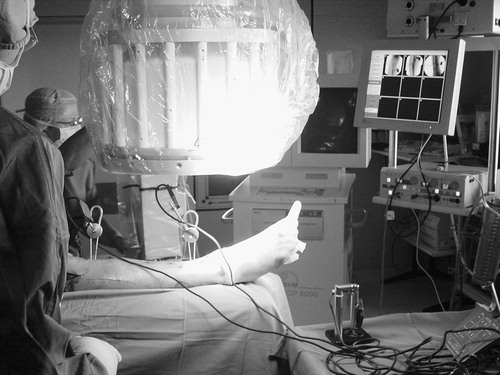
Subsequently, the C-arm may be removed from the operation field. For the use of the presented system, no preoperative data such as CT or MR image are necessary. All image data are acquired intraoperatively, representing the actual situation in the operating room. The presented system allows the acquisition of up to nine different C-arm images. After automatic undistortion, they are stored in a ‘library’. For each C-arm image, this library keeps track of the graphical data (GIF image) and the calculated projection parameters as determined from the tracked orientation and position of the C-arm during image acquisition. Sterile manipulation with the help of the virtual keyboard allows the individual setting of zoom factor, rotation, brightness, and contrast for each of the images. Various calibrated instruments, such as a pneumatic drill, screw driver, and so on, are then connected to the navigation system, and their correct calibration is verified. Given successful verification, each of the tools is available for image interactive navigation in any of the acquired images immediately. For this purpose, subsets of up to four images are selected from the library and are displayed simultaneously during each phase of the intervention. The current tool position is projected onto the different image planes in real time.
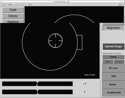
One of the crucial steps of this procedure is the acquisition of correct, that is, helpful, X-ray projections. To facilitate this step, a special alignment mode is provided by the navigation system. Any navigated freehand instrument may be used to identify a desired projection axis prior to image acquisition. The associated trajectory is captured and stored by the system. With the help of a graphical user interface (), the C-arm may then be precisely aligned with the previously defined axis. As a result of this approach, the acquisition of fluoroscopic images can be standardized for each type of intervention, which helps to improve quality and reduce radiation exposure.
Figure 2. Alignment mode for precise placement of the image intensifier.
Reality enhancement
For the integration of the three-dimensional geometry of navigated instruments and implants into the navigation process, it was hypothesized that by this approach more complex objects such as osteosynthesis plates or nails could be visualized within C-arm images in a more realistic way. For this purpose, three-dimensional computer-aided design (CAD) drawings served as input. To avoid the need for re-acquisition of images after bony manipulations, the simultaneous dynamization of conventional fluoroscopic images in different projection planes was developed. Dynamization denotes the segmentation of bony objects within individual images and the independent referencing and tracking of the associated fragments. It was assumed that this technique would enable a more realistic visualization of the three-dimensional fracture reduction process in navigated C-arm images.
The dynamization of the images used the concept of ‘virtual cylinders’, which benefited from the cylindrical shape of long bones. Two steps were necessary to prepare data for dynamization. First, the axis of each fragment was determined by manually reconstructing its two ends using a biplanar landmark reconstruction technique as shown in . A cylinder was created around this axis and was visualized taking the acquired images as background. The radius and length of the cylinder were manually adjusted until the projection of this cylinder encapsulated the associated fragment within each image. This task was carried out by an assistant using the computer mouse. In a second step, the projection of the cylinder, a quadrilateral, was used to separate the fragment that it encapsulated from the background of the X-ray image (). A deformable model-based method Citation[19] was used to find the contours of the fragment. For each point on the contour, four interpolation weights relative to the four vertices of the cylinder projection were calculated using a Newton-type downhill optimization algorithm, which completed the preparation for dynamization. Spatial changes in position of the associated bone objects (as determined by the tracking system) resulted in positional changes of each cylinder, as well as the four vertices of its projection. On the basis of the new positions of its projection and the stored interpolation weights, the virtual projection of the fragment could be determined and was used to warp the segmented image section over the static background.
Figure 3. Virtual three-dimensional space created from two-dimensional X-ray projections.
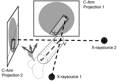
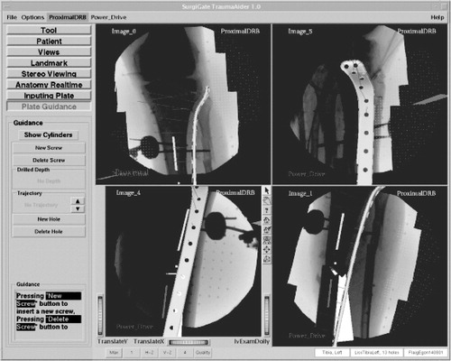
It was therefore possible to control the reduction process in real time in a radiation-free manner. The fracture reduction of the two main fragments was displayed to the surgeon as axial alignment in two planes (frontal and sagittal), as well as length and rotation of the fragments. A further step towards enhanced reality in virtual fluoroscopy was the aforementioned three-dimensional visualization of tools in two-dimensional images. Using the known locations of the X-ray source and intensifier unit during image acquisition, as well as two projected images, a three-dimensional space was reconstructed in which the operated bony structures and all navigated tools were placed in relation to one another Citation[17] ().
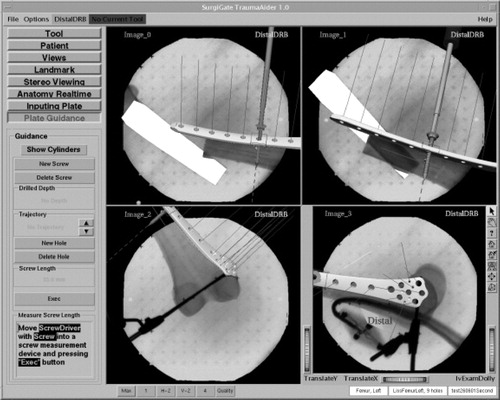
Figure 4. User interface with visualization of X-ray dynamization and three-dimensional representation of a fracture fixation plate.
Clinical application
The LISS® (Stratec-Medical, Oberdorf, Switzerland) is an osteosynthesis system allowing for the minimally invasive fixation of problematic metaphyseal fractures with angular stabilization. In a sense, it is comparable to an internal fixator Citation[12]. However, its implantation is challenging and usually does not allow any errors. The usual ‘reduction against the plate’ known from conventional fracture treatment is inapplicable. Instead, the implant has to fit the convexity of the bone precisely.
After successful laboratory evaluation, the newly developed module was integrated into the existing navigation system. This technology was then applied during osteosynthesis supported by LISS for the first time in our clinic. We performed a consecutive case study of three patients with four fractures of the proximal tibia between June and August 2001. All patients were primarily fixed with an external fixator or unreamed tibia nailing (UTN) and secondarily stabilized with the LISS. Two patients had combined proximal tibia fractures with severe soft tissue damage (third degree) owing to the accidents that had caused their fractures. In the primary treatment, the fractures were stabilized by external fixation. The soft tissue damage was treated by local flaps or skin transplantation. After healing of the soft tissue, the treatment was changed from external fixation to internal stabilization. One patient with a proximal tibia fracture and second-degree soft tissue damage was treated with a UTN in another hospital. In this patient, a severe instability remained. All patients were in follow-up for 18 months.
OR time, blood loss, and X-ray duration were recorded intraoperatively. The sequence of the navigation part of the operation was as follows.
First, DRBs were fixed to the proximal and distal main fragments. Fluoroscopic images were acquired in two different planes, both proximally and distally of the fractures, as well as at the levels of the fractures. Subsequently, the fractures were reduced and fixated with navigational support ( and ). With the help of the virtual cylinder concept, three-dimensional structures were created from the image pairs that represented the bone volumes. As a result, the acquired images could be dynamized, and the entire reduction procedure could be carried out without additional fluoroscopic checking. Owing to the interactive feedback of the displayed and tactile information during surgery, the reduction could be performed in all cases in a simple and fast manner. In real time, the LISS plates, the drill, and the screw driver with the attached screws were visualized three-dimensionally and in their correct spatial relation to the acquired images. The insertion of the plates, as well as the subsequent fixation procedure including drilling, depth measurement, and screw insertion, could be navigated. The acquisition of two C-arm images of the fracture area for verification purposes completed the procedure. These final images were acquired from different directions with both DRBs and the LISS marker shield still in place. As a consequence, the resulting images could be re-loaded into the navigation system and the matching between the X-ray shadow of the implanted plate and its overlaid graphical model could be verified.
Figure 5. Intraoperative application showing navigated reduction and osteosynthesis.
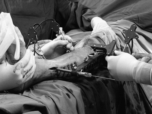
Figure 6. Corresponding visualization on the monitor screen.
Results
All operations were performed by the same surgeon (P.A.G.). In all cases, the planned procedure could be performed and was successfully supported by the navigation system. No intraoperative or postoperative complications occurred. All patients healed uneventfully and started full weight bearing after 6 weeks. The clinical data are summarized in .
Table 1. Clinical information for patients treated with the prototype system.
It was shown to be possible to carry out the entire reduction and fixation procedure under navigational guidance without the need for additional image updates and the associated radiation exposure. During all four surgeries, correct fracture reduction and plate placement was achieved at the first attempt. This was documented in postoperative whole-bone X-rays in standard projections. Disadvantageous were the uncomfortable interface of this prototype software and the necessity of having an additional person control the application. When compared to the conventional approach, time for surgery and blood loss were in the range for non-navigated LISS plating in our clinic.
Discussion and conclusion
The persisting problem in minimally invasive fracture reduction is related to the precise and atraumatic reduction of the main fragments. The repetitive checking of reduction during surgery and interference between reduction and the fixation of implants are the most demanding and time-consuming elements. The aims of this project were to provide radiation-free control mechanisms during fracture reduction by navigated C-arm images (virtual fluoroscopy) and to represent implants and instruments three-dimensionally to overcome the aforementioned difficulties. There is no need for preoperative planning steps such as image processing or interactive definition of anatomical landmarks. The system does not require the intraoperative registration of preoperative image data (matching) as is mandatory for CT-based navigation. Another advantage of virtual fluoroscopy is the ability to update the navigational image data at any time, which may become necessary after changes to the anatomical situation owing to fracture reduction maneuvers or osteotomies.
The proposed virtual cylinder concept, combined with virtual fluoroscopy, provides the surgeon with three-dimensional virtual models of the bone fragments and offers several advantages: It allows the simultaneous display of several views of the fractured bone during reduction, and it is possible to visualize the fracture, including axial, rotational, and length alignment, from any viewpoint. With this reality-augmented navigation system, a close, indirect reduction in the real world has been turned into an open, direct reduction in the virtual world. This allows the control of instruments through direct insight into the virtual world. Furthermore, it also facilitates the effective extraction of the contour of the fragment from the projection image. Further development led to an algorithm that, for the first time, allowed radiation-free updates of fluoroscopic images, which considerably decreased the radiation exposure for the surgical team.
Furthermore, a universal concept is proposed to navigate various implants. This not only allows realistic visualization of virtual implants, but also provides the surgeon with additional navigation information and functional parameters for any given implant. A generic database structure, combined with two generic operations defined on it, allows easy extension to accommodate any newly developed implant on the one hand and flexible integration with any navigation system on the other hand. Our preliminary work on the integration of the LISS plate for fracture reduction and fixation has verified these points.
The proposed non-photorealistic rendering method for the visualization of virtual surgical instruments or implants not only allows the surgeon to interpret the associated three-dimensional structures, but also keeps the image details from occlusion for a better understanding of the positional relationship between surgical instruments or implants and underlying anatomy using the acquired image as the projection background.
Several advantages were observed in this preliminary clinical trial. The fracture reduction could be achieved and monitored without acquiring new fluoroscopic images throughout the surgical procedure. In a conventional setup, multi-planar visualization would have required the use of four C-arms operating continuously from different viewing angles. The visualization of fracture reduction and implant placement could be achieved simultaneously. This paves the way for less invasive fracture reduction and fixation. In our clinical cases, no implant misplacement was observed because of the direct visual feedback provided by the reality-augmented virtual system. All the implants were ideally positioned at the first attempt. Radiation time was low compared to that for the conventional procedure.
One disadvantage could be the unfamiliar operation of the software and the need for an additional operator for the navigation system. By nature, long-bone fracture fixation is an emergency operation for which the assistance of a software engineer in the operating room cannot be planned. Finally, this was the reason that it was not possible to implement this very useful tool in clinical routine procedure. We therefore could not ultimately prove whether this technique was superior to any standard procedure. Consequently, the main focus of further software development is the improvement of user friendliness.
In an ongoing project, we are developing a completely new algorithm for the automatic detection of long-bone fragments in fluoroscopic images. Once completed, this will be the basis for an updated version of the described system in which the intraoperative work-flow will be optimized for simple system control by the standard OR team. This will be the supposition for clinical studies and application in more challenging cases than demonstrated in this clinical trial.
Navigation systems are quickly spreading through operating rooms in traumatology and orthopedics. This technology does not turn novices into experts, but should be seen as a useful tool for the experienced surgeon that helps improve both the quality of the process and outcome. Our experience shows that only repeated use of navigation during standard cases trains the operating surgeon sufficiently and leads to acceptance by the surgical staff and ultimately to reliance on the system. The future will show whether the individual patient benefits from this technology alone or whether it also has positive socio-economic effects by reducing the intraoperative complication rate.
Navigation systems and, in particular, the associated software programs undergo constant improvements including better user interfaces, easier interaction, and, last but not least, reduced costs. As a consequence, their broader application can be predicted.
Future advancements of our system aim at the simplification of the intraoperative setup, the improvement of image quality, and the adaptation of new instruments. Although the virtual cylinder concept that we presented in this article allows for effective bone extraction from fluoroscopic images, it can only provide a rough approximation of reality. More development needs to be carried out to transfer the simplified augmented-reality approaches to a full three-dimensional virtual surgical scene. Three-dimensional model reconstruction based on a limited number of registered projections should be investigated. The reconstructed model could be used to provide more precision in the representation of the related anatomy.
The preliminary implementation of the proposed concept for navigating various implants could be further expanded. The solutions realized so far are focused on a particular type of implant and do not define a common data format to store this information for use in different planning and navigation applications.
The potential of the technique appears gigantic. Advantages that can be identified now include the reduction of intraoperative radiation doses for the patient and surgical staff, as well as the improved operative precision guaranteeing more safety for the patient.
Navigated LISS osteosynthesis can overcome the disadvantages of the minimally invasive procedure by visualizing reduction, implant placement, and fixation.
Acknowledgement
Parts of this work were funded by the AO/ASIF Foundation—AO Research Project 2000-G3.
References
- Babst R., Hehli M., Regazzoni P. LISS tractor. Combination of the ‘less invasive stabilization system’ (LISS) with the AO distractor for distal femur proximal tibial fractures. Unfallchirurg 2001; 104: 530–535
- Krettek C., Gerich T., Miclau T. A minimally invasive medial approach for proximal tibial fractures. Injury 2001; 32(Suppl 1)SA4–SA13
- Rampersaud Y. R., Foley K. T., Shen A. C., Williams S., Solomito M. Radiation exposure to the spine surgeon during fluoroscopically assisted pedicle screw insertion. Spine 2000; 25: 2637–2645
- Foley K. T., Simon D. A., Rampersaud Y. R. Virtual fluoroscopy: computer-assisted fluoroscopic navigation. Spine 2001; 26: 347–351
- Hofstetter R., Slomczykowski M., Sati M., Nolte L. P. Fluoroscopy as an imaging means for computer-assisted surgical navigation. Comput Aided Surg 1999; 4: 65–76
- Nolte L. P., Slomczykowski M. A., Berlemann U., Strauss M. J., Hofstetter R., Schlenzka D., Laine T., Lund T. A new approach to computer-aided spine surgery: fluoroscopy-based surgical navigation. Eur Spine J 2000; 9(Suppl 1)S78–S88
- Slomczykowski M. A., Hofstetter R., Sati M., Krettek C., Nolte L. P. Novel computer-assisted fluoroscopy system for intraoperative guidance: feasibility study for distal locking of femoral nails. J Orthop Trauma 2001; 15: 122–131
- Hofstetter R., Slomczykowski M., Krettek C., Koppen G., Sati M., Nolte L. P. Computer-assisted fluoroscopy-based reduction of femoral fractures antetorsion correction. Comput Aided Surg 2000; 5: 311–325
- Suhm N., Jacob A. L., Nolte L. P., Regazzoni P., Messmer P. Surgical navigation based on fluoroscopy—clinical application for computer-assisted distal locking of intramedullary implants. Comput Aided Surg 2000; 5: 391–400
- Nolte L. P., Visarius H., Arm E., Langlotz F., Schwarzenbach O., Zamorano L. Computer-aided fixation of spinal implants. J Image Guided Surg 1995; 1: 88–93
- Nolte L. P., Zamorano L., Visarius H., Berlemann U., Langlotz F., Schwarzenbach O. Clinical evaluation of a system for precision enhancement in spine surgery. Clin Biomech. Bristol, Avon 1995; 10: 293–303
- Visarius H., Gong J., Scheer C., Haralamb S., Nolte L. P. Man–machine interfaces in computer assisted surgery. Comput Aided Surg 1997; 2: 102–107
- Glossop N., Hu R. Effects of tracking adjacent vertebral bodies during image guided pedicle screw surgery. Proceeding CVRMed–MRCAS'97, J. Troccaz, E. Grimson, R. Mösges. Springer, Berlin 2003; 531–540
- Joskowicz L., Milgrom C., Simkin A., Tockus L., Yaniv Z. FRACAS: a system for computer-aided image-guided long bone fracture surgery. Comput Aided Surg 1998; 3: 271–288
- Slomczykowski M., Hofstetter R., Burquin I., Nolte L. P., Synder M. The method of computer-assisted orthopedic surgery based on two-dimensional fluoroscopy: the principles of action. Chir Narzadow Ruchu Ortop Pol 1998; 63: 443–450
- Grützner P. A., Vock B., Wentzensen A. Use of computer-assisted, fluoroscopy-based navigation in treatment of pelvic ring disruptions. Computer Assisted Radiology and Surgery (CARS 2000), H. U. Lemke, M. W. Vannier, K. Inamura, A. G. Farman, K. Doi. Elsevier;, Amsterdam 2000; 965
- Grützner P. A., Vock B., Zheng G., Kowal J., Nolte L., Wentzensen A. Minimal invasive, computerassistierte Plattenosteosynthese bei Frakturen langer Röhrenknochen. Hefte zu: Der Unfallchirurg 2001; 283: 160
- Grützner P., Korber J., Wälti H., Nolte L. P., Wentzensen A. CT-free navigation for acetabular cup placement. Abstracts from CAOS-International 2002. Comput Aided Surg. Second Annual Meeting of the International Society for Computer-Assisted Orthopaedic Surgery, Santa Fe, NMUSA, 2002; 8: 111–130
- Cohen L. D. On active contour models ballons. Comput Vision Graph 1991; 53(2)211–218