Abstract
Objective: A prospective study is presented on the amount of targeting error that is due to rotational deviations between the atlas and the stereotactic coordinate system.
Materials and Methods: We investigated 14 volunteers with a stereotactic frame fixed to their heads by tight adhesive bands. Sagittal, coronal and axial T2-weighted MRI scans, as well as MPRage sequences, were performed. The anterior and posterior commissures and one additional point on the midline (the septum pellucidum) were determined on the axial T2-weighted images. Bilateral atlas coordinates for the subthalamic nucleus (STN), globus pallidus pars interna (GPi) and nucleus ventralis intermedius (Vim) were transformed to stereotactic frame coordinates, either without correction or by 2-point or 3-point correction. A total of 896 coordinates (x, y, z for the STN, GPi and Vim in both hemispheres) were calculated.
Results: Although the mean differences between the two algorithms (0.24 ± standard deviation of 0.33 mm) were within the range of system-immanent inaccuracies in MRI-guided stereotaxy, deviations of up to 2.8 mm occurred. No significant correlation was found regarding the amount of rotational angle and the differences in x-, y-, or z-coordinates when 2-point and 3-point transformations were compared.
Conclusions: The reliability of meticulous trajectory planning might be compromised significantly by using only 2-point-based correction or no calculations at all.
Introduction
Every neurosurgeon involved in stereotactic procedures is confronted with the problem of coordinate transformations. The surgeon must frequently rely on atlas-derived target points, especially in those cases in which the target is not immediately visible on the MRI or CT scans. The atlas coordinate system is usually based on the intercommissural line between the anterior and the posterior commissures Citation[1], Citation[2]. The three axes of this atlas coordinate system (antero-posterior, right-left and superior-inferior) are hardly ever parallel to the axes of the stereotactic system, which is defined by the geometry of the stereotactic frame and is fixed to the patient's head. Thus, a transformation of the atlas-derived coordinates to the frame coordinates is thought necessary. In the literature, several algorithms have been proposed to overcome this problem Citation[3–6]. In addition, commercial software products are available for use in stereotactic planning, such as the @Target software and iPlan-Stereotaxy (BrainLab, Heimstetten, Germany), the FrameLink™ Stereotactic Linking System (Medtronic, Minneapolis, MN) and the Leksell SurgiPlan System (Elekta, Stockholm, Sweden). In our institutions we use the @Target software from Brainlab, as mentioned in the Methods section. However, personal discussions and visits to experienced deep brain stimulation centers have revealed a great variety of planning procedures ranging from the use of 3-point-/2-point-correction algorithms to no correction of rotational errors at all. We therefore questioned whether the differences between the correction algorithms are clinically relevant (>1 mm) and if these differences might be estimated by simply looking at the rotational angles between the atlas coordinate system and the stereotactic frame (). Accordingly, a prospective study was performed including 84 target points.
Methods
We investigated 14 volunteers (9 females and 5 males; age: 23 to 46 years). The heads of the volunteers were firmly attached to a stereotactic MRI-compatible ring and frame (Stryker Leibinger, Freiburg, Germany) which had already been fixed to the table of the MR scanner. MR imaging was performed involving volumetric T1-weighted MRI (voxel size 1 mm, slice orientation sagittal, TR 11.4 ms, TE 4.4 ms, 1 acquisition, matrix 256 × 256 (100%), FOV 250 mm) and, for targeting, two T2WI spin-echo MRI sequences (slice thickness 3 mm, slice orientation axial and coronal, TR 3000 ms, TE 80 ms, 2 acquisitions, no distance factor, matrix 256 × 256 (100%), FOV 250 mm, TA 25:40 min, 60 slices). The axial T2-weighted images were acquired parallel to the intercommissural plane with a Siemens Magnetom Vision 1.5-Tesla MR scanner (Siemens, Erlangen, Germany). If motion artefacts were detected on the images, the measurement was repeated either in the same session or a second session. All acquired MR images were transferred to a computer workstation, where all data sets were fused to the volumetric T1-weighted MRI (@Target software, BrainLab, Heimstetten, Germany). The coordinates of the anterior commissure (AC) and posterior commissure (PC) were determined on the axial T2WI spin-echo images and the coordinates of the mid-commissural point (mid-AC-PC) and the AC-PC distance were calculated accordingly. The width of the third ventricle was measured in the axial plane of AC-PC.
The coordinates of three targets, the subthalamic nucleus (STN), the ventral intermediate nucleus (Vim), and the internal segment of the globus pallidus (GPi), were defined for both hemispheres as follows:
| STN: | = | 12 mm lateral, 3 mm posterior and 3 mm inferior to mid-AC-PC. |
| GPi: | = | 20 mm lateral, 3 mm anterior and 4 mm inferior to mid-AC-PC. |
| Vim: | = | Half of the third ventricle width ± 11.5 mm lateral; 3.5/12 of the intercommissural line anterior to the PC; right on the horizontal plane of the intercommissural line. |
Results
The differences between the results from 3-point and 2-point correction algorithms ranged from 0 mm to 2.8 mm (mean: 0.24 ± 0.33 mm) with regard to all coordinates. When comparing results obtained using the 3-point correction algorithm with those obtained without rotational correction, the range was slightly narrower (0 to 2.6 mm), but the mean difference was significantly higher (mean: 0.58 ± 0.56 mm; p < 0.05). The differences between results obtained with 3-point-based calculation and those obtained with no calculation for rotational deviations reached statistical significance for the x- and z-values (p < 0.05).
Considering the x-coordinates alone, the comparison between the calculation differences (2-point versus 3-point) showed the least deviation for x in the Vim followed by the STN. The calculation difference for the x-coordinates in the GPi was significantly higher than those for the x-coordinates in the other two targets (p < 0.05). Likewise, differences for z-values were lowest in the Vim and STN and significantly higher in the GPi (p < 0.05).
The two correction algorithms showed no statistically significant differences for y-coordinates in the Vim, STN or GPi.
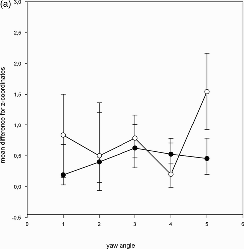
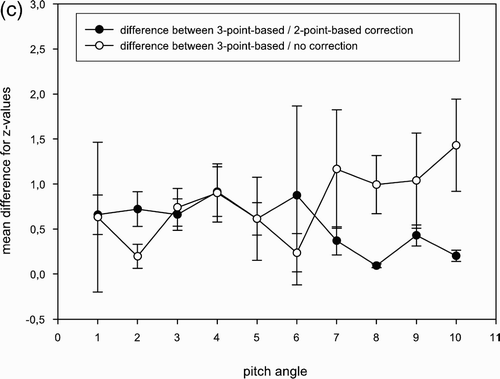
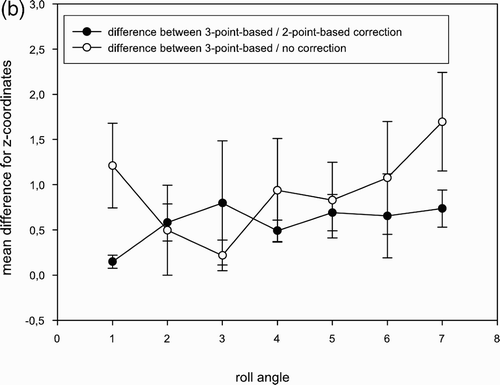
In all targets (STN, GPi, Vim), differences in the y-values were the least pronounced and differences in the z-values highest ().
Table I. Differences between results obtained with 2- and 3-point correction algorithms.
The pitch angle ranged from 0° to 6°, the roll angle from 0° to 7° and the yaw angle from 0° to 22° (). Comparing the coordinates before and after 3-point corrections, the differences tended to be higher the more the stereotactic ring was tilted with respect to the AC-PC line. However, with regard to the difference between 3-point-based-/2-point-based calculations, we found no significant correlation between the amount of rotation angle and the difference in the x-, y-, and z-values ().
Discussion
The mean differences between results with the 3-point-based and 2-point-based correction algorithms for rotational errors were found to be well below 1 mm for all x-, y-, and z-coordinates. Even the mean differences between results obtained with the 3-point-based correction algorithm and those obtained without any correction were clearly below this value. This might suggest that correction algorithms are not necessary and that the money expended on special software programs could be saved, since in “real stereotactic life” the accuracy of the stereotactic frame and aiming device, as well as the inaccuracies due to MR image distortion and slice thickness, lie within the range of these differences Citation[7], Citation[8]. However, distances up to 2.8 mm were found, and the trajectory to the target is displaced accordingly, which casts doubt on the reliability of the trajectory planning. As performed in our institution in deep brain stimulation for movement disorders, every single MRI slice is checked for contact between the five microelectrode trajectories and the intracerebral blood vessels after double-dose i.v. gadolinium injection. If a target error of 2.8 mm were to occur, it is our opinion that the risk of intracerebral hemorrhage might increase significantly.
The most lateral and most inferior target (the GPi) showed the greatest difference between the calculated x- and z-values. This is what would be expected from the mathematical considerations. Probably due to the small differences between the y-coordinates of the targets, the differences of the calculation results in the antero-posterior direction did not reach statistical significance. A roll of as little as 3° can cause a targeting error on the order of 1 mm when a 2-point algorithm is used and, as a prerequisite, the y- and z-axes are parallel to the corresponding axes in the stereotactic system Citation[3]. In most cases, at least two of the axes of each coordinate system were not parallel to the corresponding axes in the other coordinate system. Hence, the estimation of the resulting values for x-, y-, and z-coordinates becomes rather complex and is hard to accomplish without the help of a dedicated mathematical algorithm.
One might suspect that working with volunteers, whose heads were firmly attached to the stereotactic ring with adhesive tape, rather than fixing the ring with the usual screws, might lead to inaccuracies in the image acquisition. Due to our extremely time-intensive MR sequences (acquisition time for axial T2WI spin-echo images only was 25 min), motion artefacts were easily detectable in the images. In these cases, the measurements were repeated in the same session or a second session. Finally, no image blurring due to motion artefacts could be detected in any of the volunteers, ruling out relevant motion of the subjects inside the stereotactic frame.
All acquired MR images were transferred to a computer workstation, where all data sets were fused to the volumetric T1-weighted MRI. This was done to avoid deviations in the detection of the anterior and posterior commissures due to image distortions in the T2WI spin-echo sequences, which occur in the anterior-posterior direction by approximately 1 mm Citation[9].
Conclusion
Although, in most cases, rotational errors are small enough not to influence surgical planning significantly, relevant inaccuracies do occur under circumstances that are not immediately obvious. Therefore, 3-point-based correction algorithms are recommended for every surgical case.
References
- Schaltenbrand G, Wahren W. Atlas for Stereotaxy of the Human Bra. 2nd edition. Georg Thieme Verlag;, Stuttgart 1977
- Talairach J, Tournoux P. Stereotaxic localization of central grey nuclei. Neurochirurgia (Stuttg) 1958; 1(1)88–93
- Taub E. Mathematical theory of stereotactic coordinate transformation: elimination of rotational targeting error by addition of a third reference point. J Neurosurg 2000; 92(5)884–888
- Ott K. An algorithm for the empirical determination of intracranial stereotactic targets. Stereotact Funct Neurosurg 1998; 71(1)29–35
- Ammannati F, Bordi L, Mennonna P, Gronchi P. Trigonometric method of computing the coordinates of invisible targets in functional neurosurgery. Letter to the editor. Stereotact Funct Neurosurg 1999; 72(1)70–72
- Krauss J K, King D E, Grossman R G. Alignment correction algorithm for transformation of stereotactic anterior commissure/posterior commissure-based coordinates into frame coordinates for image-guided functional neurosurgery. Neurosurgery 1998; 42(4)806–811
- Kitchen ND, Lemieux L, Thomas DG. Accuracy in frame-based and frameless stereotaxy. Stereotact Funct Neurosurg 1993; 61(4)195–206
- Dormont D, Zerah M, Cornu P, Parker F, Aubert B, Sigal R, Francke J P, Zouaoui A, Marsault C. A technique of measuring the precision of an MR-guided stereotaxic installation using anatomic specimens. AJNR Am J Neuroradiol 1994; 15(2)365–371
- Hamel W, Schrader B, Weinert D, Herzog J, Volkmann J, Deuschl G, Muller D, Mehdorn H M. MRI- and skull x-ray-based approaches to evaluate the position of deep brain stimulation electrode contacts - a technical note. Zentralbl Neurochir 2002; 63(2)65–69


