Abstract
An Internet survey demonstrated the existence of problems related to intraoperative tracking camera set-up and alignment. It is hypothesized that these problems are a result of the limited field of view of today's optoelectronic camera systems, which is usually insufficiently large to keep the entire site of surgical action in view during an intervention. A method is proposed to augment a camera's field of view by actively controlling camera orientation, enabling it to track instruments as they are used intraoperatively. In an experimental study, an increase of almost 300% was found in the effective volume in which instruments could be tracked.
Introduction
Optoelectronic camera systems that track either light-emitting diodes (LEDs) or light-reflecting markers have become the state of the art in freehand navigation systems for orthopaedic surgery. Their accuracy, reliability, and ease of use make these devices ideal for precise measurement of the position and orientation of surgical instruments. However, a number of restrictions are inherent to optoelectronic tracking and need to be addressed if such a tracker is used intraoperatively as part of a surgical navigation system.
One sometimes-cumbersome characteristic of optoelectronic tracking is the limited field of view (FOV) available with the camera systems employed. In such a tracking system, there is a more or less cylindrical volume in which objects are “visible” to the camera. As soon as a tracked LED or marker leaves this volume it becomes undetectable. To avoid this adverse effect, the camera system must be positioned within the operating room in such a way that its FOV will encompass the surgical site. Intraoperative re-centering of the camera may be required if the surgical site shifts relative to the camera's FOV, e.g., after patient repositioning. To facilitate these positioning tasks, most navigation systems offer a guidance mode, during which the software provides graphical feedback about the location of observed instruments within the FOV. Alternatively, optical feedback by means of laser beams Citation[1] has been proposed. In this solution, one or more lasers mounted on the tracking camera project the contour of the tracker's FOV in a way similar to that in which an X-ray device indicates the location its central beam or a CT scanner denotes its central axis.
Camera re-orientation is obviously more likely to be required in those computer-assisted procedures involving a large field of action or during which instruments need to be observed at different locations over the course of the intervention. An example is computer-assisted total knee replacement, which requires anatomical landmarks to be acquired at the hip, knee, and ankle joint Citation[2].
This paper introduces a technical solution to the above problems by actively controlling the camera's orientation in order to keep the tracked instruments and bones in focus.
Materials and methods
Survey
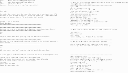
To verify that the aforementioned difficulties actually occur during the regular use of navigation systems, an Internet-based survey was conducted. An e-mail questionnaire () was sent to the internal mailing list of the International Society for Computer Assisted Orthopaedic Surgery (CAOS-International). This list currently has some 350 subscribers and represents a large group of users of computer-assisted navigation systems for applications in orthopaedics and traumatology. The responses to the questionnaire were analyzed with regard to intraoperative difficulties that could be attributed to non-optimal camera alignment.
Technical set-up
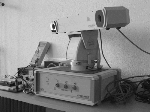
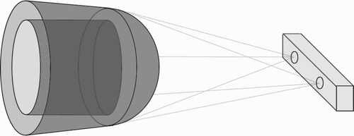
A prototype of the envisioned system was built in the form of a “volume expansion toolkit” (VET). The VET is a combined hardware-software solution that actively controls the tracking camera's orientation, allowing it to follow tools as they leave the FOV. In its prototype configuration, the VET consisted of three hardware elements (). The Polaris tracking system (Northern Digital, Waterloo, Ontario, Canada) was used as an optoelectronic tracker. It was mounted on a TV8320 motorized pan-tilt assembly (SECPLAN, Reichelsheim, Germany). This device allows for rotations of ± 180° around the vertical axis and ± 35° around the horizontal axis with a maximum speed of 6°/second. A Fischertechnik Intelligent Interface (Createc, Worb, Switzerland) enabled a Linux PC to control the TV8320. To automatically control the camera's orientation, software was developed in C + +. This software issues commands to the pan-tilt assembly via a serial connection with the Intelligent Interface. The tracking algorithm relies on several concepts to follow instruments. Firstly, a bounding space is defined, which represents a subspace of the actual volume in which the camera is able to track instruments. The bounding space provides a sensitive border area, which allows the system time to react as instruments approach the periphery of the FOV. Whenever an observed instrument enters this space, it is considered an object that is in danger of leaving the camera's FOV and appropriate care is taken not to lose it (see below). Varying the width of the bounding space affects the sensitivity of the procedure: Shrinking the bounding space makes the algorithm react more quickly, whereas increasing the bounding space leads to later detection of moving instruments, and hence corresponds to a less sensitive control mechanism. illustrates the Polaris camera, its volume, and a typical bounding space.
Figure 2. Prototype set-up of the volume expansion toolkit. The Polaris camera is mounted on a two-axis pan-and-tilt unit, which is controlled by a PC (not shown) through a programmable interface.

Figure 3. A cylindrical sub-volume of the camera's field of view is defined as a bounding shape in which tracked instruments may move without camera augmentation.

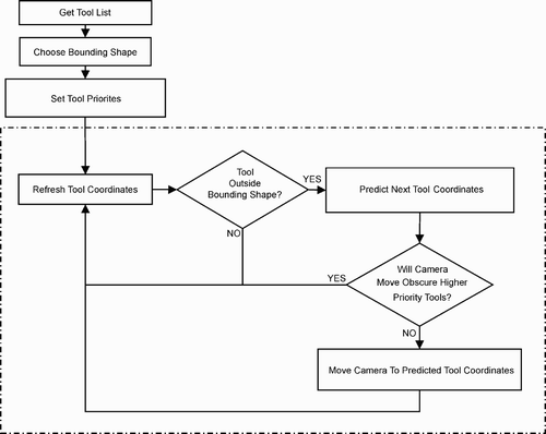
When an instrument intersects the surface of this bounding space, the future position of each tool in view is predicted. The camera is then moved to center the average predicted position of the tracked instruments. The prediction mechanism assumes linearity of tool movement, and thus requires only two frames of tool coordinates (present and past) to make a prediction. Special care must be taken in order to cope with multiple diverging instruments. If one object (e.g., a tracked surgical instrument) moves away from another one (e.g., the patient's reference frame), an instrument priority list enables the control algorithm to decide which tool to drop once their relative distance becomes too large for both instruments to fit into the camera's FOV. The control loop of the tracking algorithm is shown in .
Figure 4. Flow-chart of the control algorithm. To initialize the application, a list of tracked tools is created, the bounding shape is defined, and tool priorities are assigned. Within the tracking loop (dotted box), each frame of tool coordinates is processed as follows: If the tools are outside the bounding shape, their future location is predicted based on linear extrapolation, and a corrective camera movement is calculated. The calculated movement will then be carried out by the pan-and-tilt unit (provided this movement does not obscure any high-priority tools).

Comparative study
A comparison study was performed to demonstrate the benefit offered by the presented implementation of the VET. The principle of this study was to measure the viewing volume of the Polaris camera both with and without augmentation using the VET. The difference in volume between the two cases provided the basis for comparison. To measure the camera's volume, a mechanical arm was used to position a rigid body with four LEDs at boundary locations of the volume, which was centered over a second rigid body representing a reference frame. A total of 96 boundary locations were collected from both the standard and augmented volumes. Every effort was made to collect a uniform distribution of locations across each boundary.
To calculate the camera's volume from the recorded data, a Delaunay tessellation was performed, breaking the volume into tetrahedrons Citation[3]. The volume of individual tetrahedrons was then calculated and summed.
Results
Survey
Regarding the Internet survey, it was possible for a surgeon to respond more than once if he/she had experience in multiple disciplines. A total of 53 responses were received, 6 of which did not meet the requirements of the study (the sender either had no experience with optical navigation systems or had never encountered any problems using them). The results of the remaining 47 responses are summarized in . They indicate that 129 out of a total of 309 reported intraoperative problems could be attributed to difficulties related to a non-optimal camera set-up or limited FOV. These results provide evidence that camera set-up and FOV limitations are problematic obstacles to the effective intraoperative tracking of surgical instruments.
Table I. Excerpt of the responses that were collected by the Internet survey.
Technical set-up
The implemented control loop, as well as the realized hardware set-up, led to the expected behavior. However, the angular speed of the TV8320 pan-tilt assembly turned out to be slightly insufficient during the simulation of normal surgical steps; the camera would lose sight of rigid bodies when instruments were moved at moderate speeds. For example, assuming a camera-tool distance of 2 m, the angular speed of the device translates into a traceable translational tool motion of approximately 21 cm/second.
Comparative study
During the comparison study, the camera's viewing volume was found to be 0.89 m3 for the standard case. When the volume was augmented by the VET, this value increased to 3.58 m3, corresponding to a growth of 280%.
Discussion
Surgical navigation systems are being applied with increasing frequency during different kinds of orthopaedic surgical interventions. The Internet survey indicated that – despite the well-known and commonly accepted advantages of this technology – a number of insufficiencies can still be observed during daily clinical application. This paper has introduced a new method for optimal camera alignment. So far, this problem has been addressed by providing feedback about the camera's FOV. Laser-based aiming devices and on-screen guidance for optimized camera orientation require manual interaction with the tracker in order to align it as suggested by the feedback method. The proposed technique offers an automated and elegant way to relieve the surgical staff of this usually non-critical but cumbersome and time-consuming task. Although the VET was designed, set up, and tested with the Polaris camera (configured to track active LED markers), the toolkit could easily be integrated and used with other optical tracking systems.
The described set-up, though fully functional, would require a small improvement in order to be capable of assisting during surgery: the pan-and-tilt speed would have to be increased. The device that served in the VET prototype was a low-cost solution designed for use in video surveillance applications. Its slowness prohibited “normal” movements of the instruments when they were used within the bounding space and the VET was actively following them. For example, moving a digitizing pointer from the hip to the knee had to take at least 3 seconds. However, much faster pan-and-tilt units are available off the shelf. presents three alternative devices that we considered when assembling our set-up (note that this list is not exhaustive). While each of these devices provides greatly increased performance as far as angular speed is concerned, they are considerably more expensive than the TV8320, and it was for that reason that we eventually decided to use a simpler pan-and-tilt unit in our study, which was intended to be a proof of concept.
Table II. Possible alternative pan-and-tilt units and their specifications. For comparison, the TV8320 used in this study is also listed.
A considerable increase in tracking volume was observed. The camera model used in the presented set-up had an approximately conical FOV with an opening angle of roughly 30°. It is obvious that this physical FOV of an optoelectronic camera is limited by the design of the tracker itself and cannot be improved by the VET. However, it is anticipated that the dynamic volume increase will be beneficial during applications such as, for example, navigated TKA, in which the camera's focus is supposed to be on the complete femur, the complete tibia, or the area around the knee, but never on the entire leg at once.
Conclusion
The survey presented in this paper showed that there are still many problems associated with intraoperative optical tracking systems. The VET is a first step toward addressing issues of camera set-up and limited field of view. With the first version of this toolkit, a significant improvement has been measured.
Acknowledgment
Parts of this study were supported by the AO/ASIF Foundation, Davos, Switzerland, and the Swiss National Center of Competence in Research on Computer Aided and Image Guided Medical Interventions, Zürich, Switzerland.
References
- Sanjay-Gopal S., Messner D. A., Czarkowski B. J.. Auto positioner. US Patent No. 6,187,018, (accessible at http://www.uspto.gov/patft/index.html)
- Kunz M., Strauss M., Langlotz F., Deuretzbacher G., Rüther W., Nolte L. P. (2001) A non-CT based total knee arthroplasty system featuring complete soft-tissue balancing. Proceedings of 4th International Conference on Medical Image Computing and Computer-Assisted Intervention (MICCAI 2001), UtrechtThe Netherlands, October, 2001, W. J. Niessen, M. A. Viergever. Berlin, Springer, 2208: 409–415, Lecture Notes in Computer Science
- Barber C. B., Dobkin D. P., Huhdanpaa H. T. The Quickhull algorithm for convex hulls. ACM T Math Software 1996; 22(4)469–483
