Abstract
Objective: This study investigated different infrared marker reference base attachments in cadaveric bone and their effects on alignment outcome when different loads were applied.
Material and Methods: Five cadaveric specimens were used to test four reference base attachments: a locking one-pin (4.0 mm and 5.0 mm pins) and a two-pin clamp (Hoffman fixator, 3.0 mm and 5.0 mm pins, Stryker Inc., NJ). Each was tested with metaphyseal and diaphyseal attachments. A navigation system (Stryker Navigation, MI) was used for testing with applied incremental loads and torques (65 N and 1.0 Nm) to the different reference base configurations.
Results: With 65 N the maximum change in distance to a verification point was 4.3 + 1.6 mm with the 4.0 mm locking pin in metaphyseal bone. No difference in verification point distances was found with any two-pin configuration. Alignment changes greater than 4° resulted with the 65 N loads and a 4.0 mm pin.
Conclusion: The results may prove beneficial in comparing the resulting error of different manufacturers and allow surgeons to realize the variability that may occur through incidental contact in the operating room.
Introduction
The use of computer navigation systems for total knee arthroplasty (TKA) is increasingly popular. Most clinical studies now published record a significant increase in lower extremity alignment or fewer outliers Citation[1–8]. Surgeons should realize that the computer systems are only as accurate as the measures followed to obtain an accurate alignment.
Operating rooms are often not perfect environments for conducting computer-assisted procedures. Whether one works with nurses, residents or surgical assistants, it is not uncommon for instruments to be inappropriately bumped during the procedure. Not only may staff be an issue, but the fact that markers and instrumentation are removed from and replaced on the reference base anchoring pins may also affect accuracy according to the tolerances of the attachment coupling.
One issue not often addressed is the stability of the anchoring method used for attachment of the active or passive markers to the femur and tibia for imageless computer-aided TKA. This study investigated the stability of one- and two-pin reference base anchoring systems for use with a commercial navigation system (Stryker Navigation, Kalamazoo, MI). Accuracy measures of infrared tracking systems do not always include the errors associated with any movement of the anchored markers during the operation, and if a more rigid anchoring system can decrease the variability measures then this would be advantageous.
It was hypothesized that not only the design of the reference base anchoring pin but also the attachment site chosen in either diaphyseal or metaphyseal bone would have a significant effect on the determined lower extremity alignment when a linear or torsional load was applied to the system. Two different designs of reference base anchoring systems with two different diameter pins were tested in a cadaveric model to determine if the number of attachment sites and location of the anchored reference base had any affect on stability of the marker under different loads.
Materials and methods
Approval from our institution's investigational review board was obtained for this study. Five fresh frozen cadaveric lower extremities were used to test four different reference base anchoring system configurations. These were based on a self-locking one-pin (Stryker Navigation, Kalamazoo, MI) and a clamped two-pin device (Hoffman external fixator, Stryker Orthopaedics, Inc., Allendale, NJ), each being tested with two different-sized pins (4.0 mm and 5.0 mm for the single locking pin and 3.0 mm and 5.0 mm for double-pin Hoffman fixator; ). Each anchoring device was tested with both a metaphyseal and diaphyseal attachment position on the femur of each cadaveric specimen. The metaphyseal anchoring position chosen was one typically used for computer navigation TKA. This was just medial of the midline and just above the point where the femoral component anterior flange would be positioned. The diaphyseal position was chosen within the isthmus portion of the femoral shaft and was 8 cm above the metaphyseal attachment point ().
Figure 1. The four tracker attachment fixation devices tested: 4.0 mm self-locking Steinman pin; 5.0 mm self-locking Steinman pin, 3.0 mm Hoffman fixator; and 5.0 mm Hoffman fixator.
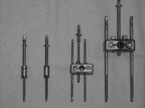
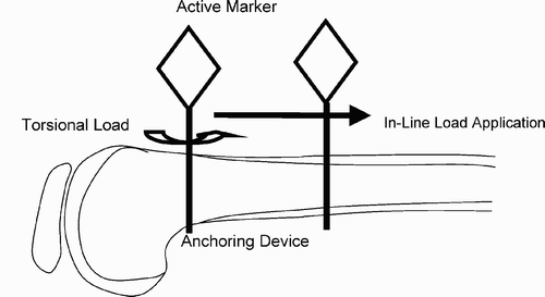
Figure 2. Schematic of distal femoral location of the metaphyseal and diaphyseal fixation points and the loads applied. This was repeated with a two-pin construct in the same regions of the femur.
A standard computer navigation system (Stryker Navigation, Kalamazoo, MI) was used for the study with markers that were active emitters. Each lower extremity was attached to a universal joint to simulate the hip. The registration process of the computer assisted navigation system was then carried out. A 3.5 mm unicortical screw was placed to serve as a verification point on the distal femur 2 cm from the anchoring device for each attachment site tested. The tibial marker was placed and left alone for the duration of the study.
The femoral marker had each of the four different anchoring systems placed both in the metaphyseal and diaphyseal regions for comparison, and none were placed in or near previous fixation drill holes. Incremental loads of 0, 10, 25, 35, 45, and 65 N were applied to each anchoring device in line with the femoral shaft, as well as perpendicular to the shaft. A calibrated spring load scale was used to apply the force along the base of the reference frame. With application of each in-line directional force, the change in distance to the verification point was recorded as well as the change in the resulting lower extremity alignment for comparison.
A torsional load was also applied from 0 to 1 Nm in five increments. This was accomplished by using the same calibrated spring scale applying the appropriate force along an open-ended wrench that fitted the marker base. While each load was applied, the change in distance to the verification point was recorded using the navigation system's pointing device as well as the change in the clinical rotations for each torsional load applied. After each of the five incremental loads were applied to the anchoring device, the verification point was checked one final time to record any permanent change in the tracker position. The changes in the verification point distances as well as the change in clinical angles were recorded and compared using a paired t test. Similarly, the difference between the various reference base anchoring systems was assessed using a t test of different means for comparison.
Results
With the 65 N load in line with the shaft of the femur, the average distance change to the verification point was a maximum of 4.3 ± 1.6 mm and occurred with the 4.0 mm single locking pin with a metaphyseal attachment point (). With a 65 N load perpendicular to the femoral shaft, the maximum change was again measured with a 4.0 mm self-locking pin with a metaphyseal attachment and was 1.3 ± 0.8 mm. The change was more sensitive to loads along the line of the femoral shaft.
Figure 3. Change in distance to the verification point under in-line femoral shaft loads for the different fixation methods.
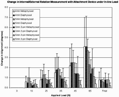
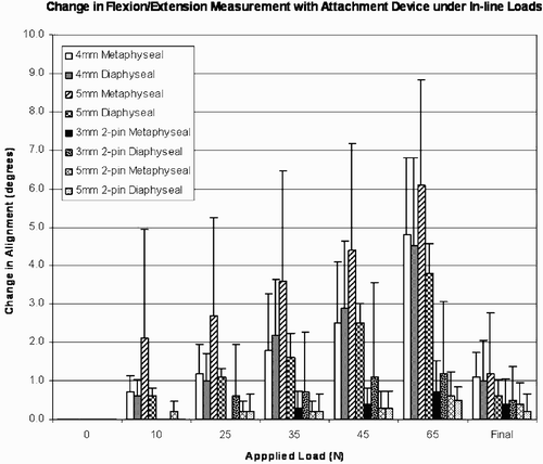
With regard to clinical rotations, varus/valgus angles changed by up to 2.5 ± 1.9°, flexion by 4.8 ± 2.0°, and rotation angles by 4.1 ± 1.9° with a linear load applied in line with the femur to the 4.0 mm pins with a metaphyseal attachment (). When a load of 25 N or more was applied to the attachment device, the two-pin configuration with 3.0 mm and 5 mm Steinman pins proved to provide significantly less variability in the verification point distance when compared to single-pin devices (p < 0.05). Neither of the two-pin configurations was statistically different when compared to each other or to a metaphyseal and diaphyseal anchoring point. When comparing the changes in the other two planes, similar findings resulted ( and ).
Figure 4. Change in resulting coronal plane alignment under in-line femoral shaft loads for the different fixation methods.

Figure 5. Change in resulting sagittal plane alignment under in-line femoral shaft loads for the different fixation methods.
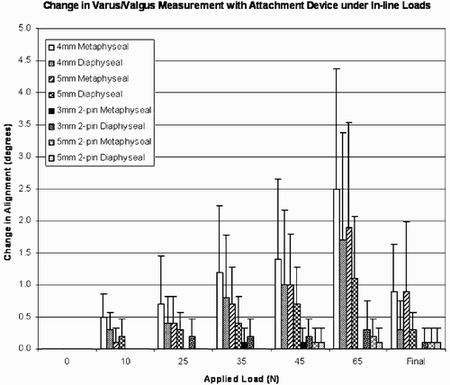
Figure 6. Change in resulting transverse plane alignment under in-line femoral shaft loads for the different fixation methods.
With regard to varying torque, only the 4 mm self-locking pin in a metaphyseal anchoring location was significantly more variable (p < 0.05) compared to the other fixation types, with a mean difference from the verification point of 2.1 ± 0.5 mm under maximum torsion. When a torsional load was applied to the reference base anchoring device, the locking mechanism to the fixation pin failed on several occasions when the applied torque was between 0.5 and 1.0 Nm. All two-pin configurations revealed no statistical differences in the distance to the verification point or in alignment in any alignment measure in the three clinical planes.
Discussion
With the advent of new technology the cost/benefit ratio is always weighed, and the use of computer navigation systems in total knee arthroplasty has been no different. Skeptics argue that the increased length in operative time and increased cost do not warrant their use, while proponents argue that the increased accuracy and deletion of outliers with poor alignment currently warrants their use for most cases Citation[1–8]. This study reports sources of errors in lower extremity alignment that may affect intraoperative measurements due to the quality of the fixation method for anchoring the reference base and markers to the femur and tibia. These sources of error are not usually taken into consideration by manufacturers of navigation systems. It has been shown that the two-pin fixation method along with a stronger tracker/marker coupling system can significantly decrease the variability in alignment and rotational measures.
Imageless computer navigated TKA faces a challenge as decreasing hospital reimbursements and increasing healthcare costs placing more strain on a hospital's bottom line, making the increased cost difficult to justify. This, along with the fact that it may take a decade to realize the clinical benefit in these cases due to more accurate alignment, provides the opponents of the technique with ammunition. However, if one views this process of computer navigation as a tool rather than a technique it becomes difficult to argue that a more accurate tool to obtain one of the goals of the surgery (neutral alignment) is not worthwhile, though surgeons who use these systems must be aware of their algorithms and possible errors to properly reap the attendant benefits. For these reasons, along with the computer algorithm adage “garbage in, garbage out”, certification for surgeons who use these systems may be beneficial.
The results of this study may also prove useful in starting a standard error measure to which each system can be compared and ensuring that each surgeon who uses a system knows where the preventable variability of measures can be avoided during the system's use in the operating room. Given this, the authors recommend that surgeons be aware of the possibility of a decrease in accuracy if outside forces are introduced to the anchoring device for the tracker or reflectors of these systems and, when possible, use a verification point to see if the system's output is still reliable whenever a reference base marker attachment has been compromised during the procedure.
Disclosure
Drs. Mihalko and Krackow are consultants for Stryker Orthopaedics, Inc. No benefit was received for this research.
References
- Krackow K A, Phillips M J, Bayers-Thering M, Serpe L, Mihalko W M. Computer-assisted total knee arthroplasty: navigation in TKA. Orthopedics 2003; 26(10)1017–1023
- Delp S L, Stulberg S D, Davies B, Picard F, Leitner F. Computer assisted knee replacement. Clin Orthop 1998, 354: 49–56
- Saragaglia D, Picard F, Chaussard C, Montbarbon E, Leitner F, Cinquin P. Computer-assisted knee arthroplasty: comparison with a conventional procedure. Results of 50 cases in a prospective randomized study. Rev Chir Orthop Reparatrice Appar Mot 2001; 87(1)18–28
- Stöckl B, Nogler M, Rosiek R, Fischer M, Krismer M, Kessler O B. Navigation improves accuracy of rotational alignment in total knee arthroplasty. Clin Orthop Relat Res 2004, 426: 180–186
- Stulberg S D, Loan P, Sarin V. Computer-assisted navigation in total knee replacement: results of an initial experience in thirty-five patients. J Bone Joint Surg Am 2002; 84-A(Suppl 2)90–98
- Sparmann M, Wolke B, Czupalla H, Banzar D, Zink A. Positioning of total knee arthroplasty with and without navigation support. A prospective, randomized study. J Bone Joint Surg Br 2003; 85(6)830–835
- Haaker R G, Stockheim M, Kamp M, Proff G, Breitenfelder J, Ottersbach A. Computer-assisted navigation increases precision of component placement in total knee arthroplasty. Clin Orthop Relat Res 2005, 433: 152–159
- Bäthis H, Perlick L, Tingart M, Lüring C, Zurakowski D, Grifka J. Alignment in total knee arthroplasty. A comparison of computer-assisted surgery with the conventional technique. J Bone Joint Surg Br 2004; 86(5)682–687