Abstract
In this paper, a new system for navigated control in functional endoscopic sinus surgery (FESS) is presented. The system allows the safe and convenient use of a shaver that can be enabled by the surgeon only within a specified working space. Preoperatively, the surgeon defines this working space in the axial slices of the CT scan. During the surgery, the positions of the shaver and patient are tracked by an optical navigation system, which calculates whether the shaver is within the working space. The navigated control electronics receives a signal from the navigation system and disables the shaver if it is outside the working space. If the shaver is inside the working space, the surgeon can set its speed freely with a foot pedal. Experimental evaluation shows that the system allows convenient and intuitive safe removal of inflamed tissue while protecting sensitive structures. The clinical applicability was proven in a clinical trial with 10 patients.
Introduction
The principle of surgical navigation, in which the position of a surgical instrument is presented to the surgeon relative to preoperative CT data, has been known since the 1980s. Since then, constant advances in the field, including new sensors and the use of smaller, simpler, and more powerful computer systems, have led to increased benefits and comfort for surgeons. However, one principle of surgical navigation remains unchanged: The currently available navigation systems have no means of preventing a possibly incorrect surgical action that is not included in the preoperative surgical planning. At the same time, however, the system “knows” throughout the surgery whether the surgical instrument is being used within or outside the preoperative planning.
Meanwhile, robots are not yet being applied in the surgical environment in daily routine. In many cases, they have proven to be too complex and task-specific, and often fundamentally change the traditional surgical workflow.
Apart from navigation and robotics, another principle for surgical assistance is navigated control, whereby the power supply to a surgical instrument is adjusted depending on its position. Currently, navigated control serves as an extension for navigation systems, facilitating the prevention of incorrect usage of motor-driven instruments like drills, mills, saws, etc. One advantage of navigated control is that there are no major changes to the surgical workflow and the surgeon can use his familiar standard surgical instruments.
In this paper, a clinical application of navigated control for Functional Endoscopic Sinus Surgery (FESS) is described. The power supply to a shaver, which is often used for the removal of inflamed tissue, is controlled so that the surgeon can only apply it within a preoperatively defined area. This allows for intuitive computer assistance, since the surgeon does not have to repeatedly monitor the position of the instrument by inspecting the display of the navigation system. Therefore, the authors expect higher safety for the patient and lower stress for the surgeon.
Clinical problem
Functional Endoscopic Sinus Surgery (FESS) is an operative technology that is applied for the treatment of chronic inflammation in the sinus. In FESS, the pathologically modified mucous membrane (polyps) is removed to restore the natural access to the paranasal sinuses. The most common cause is polyposis nasi, which was diagnosed approximately 221,000 times in Germany in one year (July 2000 to June 2001) Citation[1]. In large hospitals, FESS is often performed 3-5 times a week. The inflamed tissue is often removed from the ethmoid (see , left), which comprises several cells with highly individual form and position Citation[2].
Figure 1. Left: Ethmoidal cells Citation[18] are often the source of the inflamed tissue. Right: The preoperative CT scan shows polyps in the right sinus sphenoidalis.
![Figure 1. Left: Ethmoidal cells Citation[18] are often the source of the inflamed tissue. Right: The preoperative CT scan shows polyps in the right sinus sphenoidalis.](/cms/asset/22a0f418-5ab8-45a0-a837-ee1b575c0c4b/icsu_a_175041_f0001_b.gif)
Despite the minimally invasive and gentle nature of FESS, serious complications can occur. These are due to the close spatial relationships between the working area and vulnerable anatomical structures, and to the highly individual anatomy. During the surgery, the lamina papyracea (the paper-thin bony wall between the sinus and the eye) or the skull base can be damaged. If these complications are not recognized during the surgery, then serious damage such as blindness or bleeding into the brain can occur.
State of the art
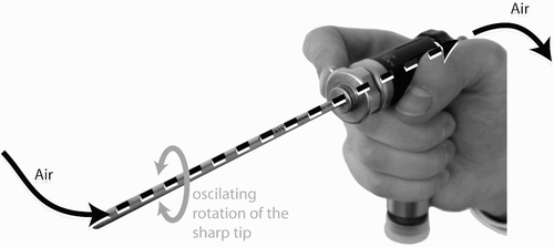
The inflamed tissue is removed on the basis of endoscopic and radiological diagnosis. The radiological diagnosis is based on axial or coronal CT scans of the suspected area. The right sinus sphenoidalis in (right) contains inflamed tissue. For the removal, a rigid straight endoscope and a Blakesley or shaver is used. A shaver is a motor-driven instrument which uses suction and oscillating rotation of a sharp tip to cut and remove tissue (see ). During the surgery, the patient is under general anesthesia Citation[1], Citation[2].
Figure 2. The shaver is a motor-driven instrument used for the removal of inflamed tissue.
There are no commercial, clinically relevant computer-based planning systems for FESS. The surgeon identifies the area of interest manually and remembers this area for the surgery. Related planning techniques are the various segmentation methods, such as manual segmentation, semi-automatic (e.g., live-wire) or fully automatic (e.g., region-growing) segmentation. However, due to the difficult anatomy where polyps, soft tissue, air and bony structures are arranged in a small area with very fine structures, no current semi-automatic or automatic technique seems sufficient for clinical application. Existing navigation systems such as BrainLAB VectorVision also offer planning functionality, e.g., definition of targets. However, this functionality is not optimized for the quick segmentation of the excision area that is performed on a daily basis Citation[3–5].
Navigation systems for ENT surgery allow the identification of endoscopically visible anatomical structures. Systems from BrainLAB, Medtronic and other manufacturers display the position of a surgical instrument in the preoperative CT or MR scans. The surgeon can touch an interesting anatomical structure like a visible bony wall with a surgical tool, and, with the help of the navigation system, identify the neighboring anatomical structures, e.g., whether a wall leads to the next ethmoid cell or to the eye Citation[6].
Navigated control has been described in reference Citation[11]. It allows the operation of a motor-driven surgical instrument like a shaver in such a way that its power is reduced outside a previously defined working area. The surgeon can thus easily distinguish the working space from vulnerable areas, and no sensitive structures can be damaged. However, no clinical application of navigated control for ENT surgery has yet been realized Citation[8], Citation[10]. Previous work in this field is described in references Citation[16] and Citation[17].
Deficit of the state of the art
The state of the art for computer assisted ENT surgery mainly comprises navigation systems. However, these systems cannot prevent the surgeon from damaging sensitive structures. Most navigation systems only display the position of the surgical tool relative to the preoperative CT data.
Another disadvantage of current navigation systems is the need for the surgeon to constantly monitor the position of his instrument on a separate display, which is often positioned near the endoscopic video screen. Therefore, the surgeon often has to interrupt his surgical procedure and shift his attention from the endoscopic video and the patient to the visualization of the navigation system.
Navigated control can prevent the incorrect use of a power-driven surgical tool like a shaver, which is used during FESS, and can therefore actively protect the anatomical structures. At the same time, navigated control should cause less stress for the surgeon than navigation systems, since the surgeon need not constantly supervise a visualization of the shaver, which will be automatically switched off if necessary even if the surgeon is concentrating only on the patient.
This paper describes the first realization and application of navigated control for FESS. The authors have developed preoperative and intraoperative planning and navigation components that allow the navigation and power control of a shaver. During the surgery, the shaver can only be switched on by the surgeon within a preoperatively defined working area, thereby preventing damage to sensitive structures excluded from this area.
Materials and methods
System workflow
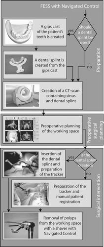
The workflow is separated into three steps (see ):
Preparation: Here the surgeon first decides between the two possible methods of patient registration. The highly precise registration with a dental splint requires manufacture of the splint and acquisition of a CT scan of the patient wearing it. The second method, manual patient registration, requires no dental splint and allows the use of any CT scan, but is less precise Citation[13–15].
Preoperative surgical planning: Here the surgeon defines the area where polyps are to be removed with the shaver.
Surgical intervention: Depending on the patient registration method chosen in the first step, the surgical intervention commences either with the insertion of the dental splint or with manual patient registration. For the latter approach, the surgeon defines four points in the planning software on the surface of the patient's face, then touches these four points on the real patient with a navigated instrument (e.g., a pointer). For both registration methods, the surgeon proceeds with the removal of the polyps within the preoperatively defined working space.
Figure 3. The workflow of the system comprises three steps: preparation, preoperative surgical planning, and surgical intervention.
System for navigated control for FESS
The components of the system are displayed in . A core component is the navigated control electronics. This evaluates the signals from the navigation system and foot pedal and can set the signal for power reduction. The signal from the navigation system indicates whether the shaver is outside or inside the preoperatively defined working space. If the signal indicates that the shaver is inside the working space, the navigated control electronics connects through the signal of the foot pedal to the shaver control unit. In this case, the surgeon fully controls the shaver. However, if the signal indicates that the shaver is outside the working space, the navigated control electronics disconnects the foot pedal from the shaver control unit, and the shaver is switched off.
Figure 4. The system contains the following hardware components: navigation system, navigated control electronics, shaver control unit, foot pedal, shaver, and patient tracker.
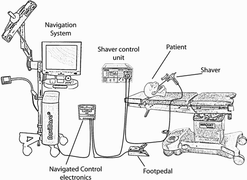
The hardware components of the system are as follows:
Navigation system. This tracks the positions of the instrument and patient using an optical sensor. The navigation system also executes the planning and navigation software.
Foot pedal. The surgeon uses this to enable or to disable the shaver.
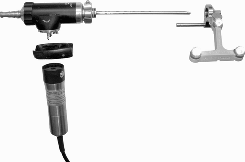
Shaver control unit. This generates the signals for the shaver motor. These signals depend on the foot pedal connected to the shaver control unit. The shaver control unit, foot pedal and shaver are manufactured by Karl Storz (Tüttlingen, Germany). The Unidrive II shaver control unit is used.
Shaver. This is equipped with an optical tracking array, allowing it to be tracked by the navigation system.
Patient (tracker). An optical tracking array was attached to the patient, so that the navigation system could track the position of the patient.
Navigated control electronics. This component evaluates the signal from the navigation system and adapts the signal from the foot pedal that is fed into the shaver control unit. This component also implements the safety architecture.
In addition to the hardware, the system contains two software components:
Preoperative planning module. This module is used by the surgeon to define the area where the polyps are to be removed.
Intraoperative navigation module. This module is used intraoperatively to evaluate the positions of the patient and shaver, which are detected by the optical sensor of the navigation system. The shaver is displayed relative to the CT data of the patient and the preoperative planning. The navigation module also calculates whether the shaver is inside or outside the working space.
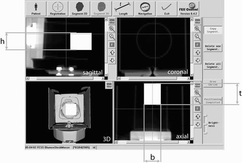
Preoperative planning
A screenshot of the preoperative planning is shown in . The surgeon imports the CT data and inspects the visualized axial, coronal and sagittal slices, as well as the reconstructed 3D surface of the patient's face. He then defines the working space in the axial slice. The authors suggest an optimized manual segmentation technique, since no robust automatic or semi-automatic methods for segmentation of a working space for tissue removal in the sinus are known.
Figure 5. The preoperative planning module allows visualization of the axial, coronal and sagittal views of the 3D surface and enables the definition of a working space for the shaver.
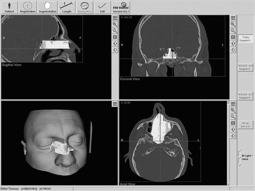
In the first step, the surgeon creates an initial segmentation by surrounding the working space with a polygon. The surgeon then proceeds with a neighboring axial slice. For a quicker segmentation, the initial segmentation is copied to this neighboring slice and the surgeon quickly adapts the polygon to the changed anatomy. For this purpose, he can add and remove border points of the polygon, and grow and shrink areas of it.
After the segmentation is complete, a 3D surface of the working space is calculated. This is visualized together with the 3D surface of the patient. The surgeon verifies the segmented area and can adjust it in the axial slice.
Navigation and navigated control of the shaver
The authors use the 90° angled shaver by Karl Storz. A tracking array (see ) was constructed and mounted on the shaver tip so that the movement of the tip can be tracked by the optical sensor of the navigation system. The patient tracking array is mounted on either the dental splint or a headband. Before navigation, the tip geometry and length of the shaver are measured. A calibration body is therefore incorporated in the patient tracker.
Figure 6. An optical tracking array can be easily connected to the shaver.
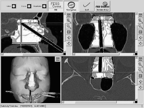
During the surgery, the shaver is displayed relative to the CT data and preoperatively created working space (see ). The color of the shaver changes to green if the shaver is within the working space.
Figure 7. Intraoperatively, the surgeon sees the position of the shaver relative to the preoperative CT data and to the preoperatively defined working space.
The working space is modeled as a voxel volume (see ). The size of the voxel volume is based on the dimensions of the CT data, e.g., if the slice thickness of the CT scan is 0.5 mm, then the height of the voxels is 0.5 mm. For a typical CT scan, the width and length of the voxel volume is 512 × 512 voxels. The working space is encoded by the color of the voxels: those outside the working space are black, while those inside are white. If the tip of the shaver is inside a white voxel, then the shaver is inside the working space.
Figure 8. The working space is modeled as a voxel volume. The size of the voxels in the figure is greater than the size of real voxels compared to the dimensions of the shaver (the shaver has a diameter of 4 mm; the typical height of the voxels is 0.5 mm).
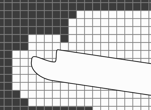
Since the shaver tip is not a point but a blade several millimeters in size, the initial voxel volume is modified. Each white voxel at the border of the voxel volume is colored black if positioning of the shaver tip at this voxel can lead to the cutting of another black voxel outside the working space. Therefore, the voxel volume shrinks. It is also possible to create several angle-dependent voxel volumes.
The modeling of the working space as a colored voxel volume has the advantage that the calculation is performed in real time. The calculation of whether the shaver tip is inside or outside the working space is constant and not dependent on the size and complexity of the working space. In an alternative approach, where the working space is modeled as a surface and the distance between this surface and the shaver is calculated, the calculation time depends on the number of triangles of the surface, i.e., on the complexity of the model. In this case, power control of the shaver would not be a real-time task, which could lead to an unknown reaction time for the system.
Navigated control electronics
The navigated control electronics is a core hardware component for the navigated control of the shaver (see ). This component is connected to the foot pedal input of the shaver control unit (interface IH2), to the power supply of the shaver control unit (IH4), to the foot pedal (IH6), to the navigation system (IH1), and between the shaver and the shaver control unit (IH3 and IH5). The connections IH4, IH3 and IH5 are part of the safety architecture.
Figure 9. The navigated control electronics is a core component that connects all the other components and controls the shaver.
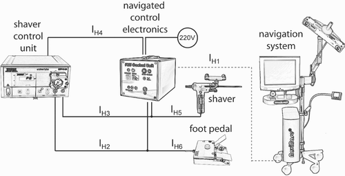
The interface IH1 transmits the result of the calculation, i.e., whether the shaver is inside or outside the working space (see the previous section). The message that encodes this result is transmitted for every cycle of the navigation system task loop. Therefore, synchronization between the navigated control electronics and the navigation system is ensured even if one or a few messages are lost. Since the optical sensors deliver the data with a frequency of 20 Hz, the navigation system and navigated control electronics communicate with 20 Hz too. Based on this signal, if the shaver is inside the working space then the electronics directly connects the signal of the foot pedal IH6 to the shaver control unit, i.e., to the signal IH2. The surgeon can then switch the shaver on and off and set its speed manually. If the shaver is outside the working space, the signal IH2 is disconnected from IH6 and IH2 is changed so that the shaver is switched off.
Based on this concept, the system never enables the shaver; only the surgeon can do so by controlling the shaver with the foot pedal, if it is inside the working space.
Safety architecture
The navigated control electronics also incorporates the safety architecture, which is based on several consistency checks and on redundant control of the shaver. The safety architecture is based on the demand that the shaver must stop in the case of a malfunction. Four types of malfunction may be detected:
The shaver is enabled outside the working space.
The shaver is not enabled even though the shaver tip is inside the working space and the surgeon has enabled the shaver with the foot pedal.
The navigation system transmits an error through the interface IH1.
There is no communication between the navigation system and the navigated control electronics.
The third malfunction is detected by special error messages that are transmitted by the navigation system. For the detection of the fourth malfunction, there is a watchdog that is triggered if the navigated control unit receives no messages from the navigation system that normally arrive with a frequency 20 Hz (see previous section).
In the case of a malfunction, the shaver stops, and the malfunction is signaled to the surgeon. There are two methods of stopping the shaver:
Set the interface IH2 to disable. This is the regular method.
Disable the power supply of the shaver control unit through the interface IH4. This is an emergency stop, which is initiated if the first method fails.
Results
As stated above, the hypothesis is that with navigated control the surgeon can remove tissue more safely than with the manual approach, and that the removal is easier than with the assistance of a navigation system. The authors also expect the surgeon to be able to create the preoperative planning within 5 min, which is suitable for clinical routine. The ergonomic and user-friendly design of the system should allow clinical use without problems.
Experiments were defined to assess the following:
Time required by a surgeon for tissue removal (manually, with navigation, and with navigated control).
Precision of tissue removal with navigated control.
Time required by a surgeon for preoperative planning.
Clinical trial with 10 patients.
Time required for tissue removal
In this experiment, the task was to remove tissue within predefined boundaries without assistance (manually), with assistance from a navigation system, and with assistance from navigated control. The time needed for tissue removal was recorded.
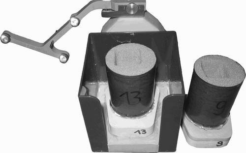
For this and subsequent experiments, a technical model was built that was open on one side. Different specimens can be reproducibly positioned in this model. The specimens were filled with plastic foam of the type used for dried flower arrangements. This foam is suitable for testing tissue removal with a shaver. The reproducible positioning was realized with magnetic clips as used in dental implantology for the fixation of dental cast models (see ).
Figure 10. Different specimens can be placed in the technical model. Reproducible placement is realized with magnetic clips familiar from dental cast models.
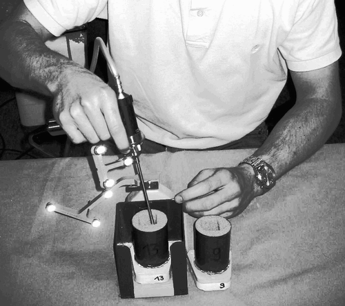
Three experiments were performed. The task for the test subject was to excise a cube of tissue. A second individual measured the time required for the tissue removal. In the first experiment, the tissue removal was based on a template lying next to the experimental installation. This template already contained a cavity of dimensions 24 × 23 × 30 mm. The test subject had to reproduce this cavity by visually inspecting the template (see ).
Figure 11. The test subject had to remove the foam manually by visually inspecting an existing template.
In the second experiment, a CT scan of the model was created. A cavity of dimensions 24 × 23 × 30 mm was created in the preoperative planning (see ). The test subject removed tissue by following the visualization of the system presented in this paper. Navigated control was disabled.
Figure 12. A rectangular cavity was defined in the planning.
In the last experiment, the test subject removed the tissue based on the same preoperative planning, but navigated control was enabled. For each of the three experiments, 5 specimens were used.
The results are summarized in . The average tissue removal time with navigated control is equal to that for manual removal, and less than the average time with the navigation system. This shows that it is easier to remove tissue with navigated control than with the support of a navigation system. In this experiment, tissue removal with navigated control was as easy as manual tissue removal.
Table 1 The time for tissue removal was measured for 15 specimens. The time required with navigated control is equal to that for manual tissue removal, and less than that for removal with a navigation system.
Precision of tissue removal with navigated control
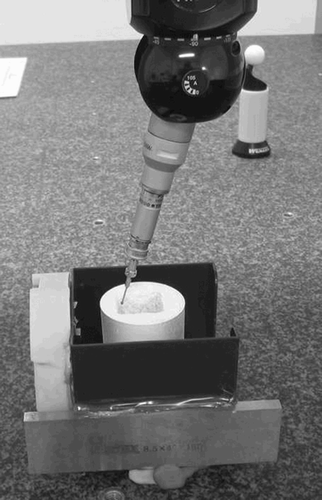
In this experiment, the task was to remove tissue within predefined boundaries with navigated control as long as the shaver was enabled by the navigation system. The size and the position of the removed cavities were measured with a precise coordinate measurement machine (CMM System LH, manufactured by Wenzel Präzision GmbH, Wiesthal, Germany). The results were then compared to the planning used for the tissue removal.
The planning from the previously described experiment was used (size of the planned cavity = 24 × 23 × 30 mm), with the same technical model and specimens. The model was registered with a dental splint, then sample points were recorded with the CMM on the five walls of the cavity (see ). The position of the measured cavities relative to the planning was calculated with a metal plate whose position relative to the dental splint was known. Therefore, the coordinates of the measured points could be transformed to the coordinate system of the planning.
Figure 13. The cavity was measured with a precise coordinate measuring machine. The coordinate transformation was achieved using a metal plate, whose coordinates relative to the dental splint were known.
A sample of the resulting data is visualized in . Here, the sampled points are displayed relative to the preoperatively defined cavity. The deviation between the planned cavity and the sampled points of the five specimens is summarized in .
Figure 14. The sampled points recorded by the coordinate measuring machine are shown relative to the planned cavity.
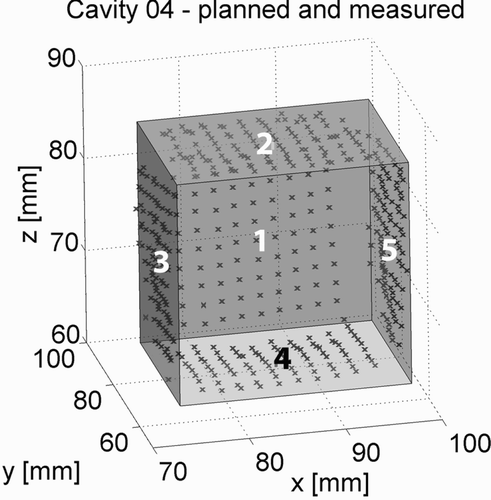
Table II. For the precision measurement, approximately 90 points were recorded on the 5 walls of the 5 specimens. The distance between these points and the planned cavity was calculated, and the mean, maximal and minimal distances, as well as the standard deviation, are displayed in this table.
The results show that the maximal exceeding of the planned cavity was 1.78 mm, while the most extreme value for a cavity being too small was 2.68 mm. This latter value is, however, due to the fact that the shaver could not reach the rectangular corners of the planned cubical cavity very well. The mean values for the deviation vary between 0.44 mm and − 0.71 mm. For best results, the size and geometry of the shaver (4 mm in diameter) must be considered. In this experiment, the working space was not reduced to compensate for the dimensions of the shaver in order to evaluate its precision.
Time required by surgeon for preoperative planning
In a third experiment, the surgeon created preoperative planning based on different patient data sets. Before the experiment, the surgeons stated that the planning must be done in less than 5 min. An experienced surgeon created working spaces for 7 patients, and a second individual measured the time required. The surgeon had to finish the task as quickly as possible with appropriate quality. Prior to the experiment, the surgeon had no experience with the system.
presents the time required for preoperative planning. In , the segmentation times are shown graphically. The goal of 5 min is shown as a horizontal line. As can be seen from these results, all planning times were faster than 5 min except for the first one. This is due to the fact that the surgeon had no prior experience with the system, and the first planning needed more time because of the learning curve.
Figure 15. The surgeons planned 7 patients; only the planning for the first patient took longer than 5 min.
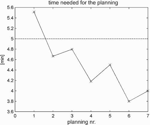
Table III. Planning times for the seven trials. Only the first planning time exceeded 5 minutes.
Clinical trial with 10 patients
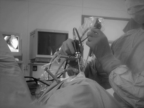
In the autumn of 2005, 10 patients were treated with the presented system at the University ENT Clinics in Leipzig. The patients had chronic sinusitis ethmoidalis and the average age was 48 years (range: 22–71 years). The surgery was performed on both sides by two experienced surgeons. Before the study, a positive vote by the ethics commission and patient's insurance were obtained.
The surgeons used the dental splint patient registration method. and show the intraoperative use of the system and an intraoperative screenshot, respectively. The results are presented in depth in reference Citation[16]. There were no complications during the surgery. The shaver reliably switched off several times as intended at places where the surgeon had anticipated the edge of the working space. In some cases, the shaver stopped unexpectedly and signaled that the surgeon had reached the edge of the working space faster than expected. On only a few occasions did the shaver switch off because of a line-of-sight problem, which was quickly solved.
Figure 16. The system was evaluated in a clinical trial at the University of Leipzig, Germany.
Discussion
The authors have presented a new system for computer assisted surgery. The system is able to prevent the use of a surgical instrument – the shaver – at an incorrect place. This prevention is realized by switching off of the shaver based on preoperative planning in which the surgeon has defined a working space for the device. Intraoperatively, the shaver and patient are tracked by a navigation system. If the shaver is moved outside the working area, then the navigation system sends a signal to the navigated control electronics, which switches off the shaver. If the shaver is inside the working area, then the surgeon can enable the shaver with a foot pedal.
The experiments show the following:
The preoperative planning is suitable for clinical use, since the time required for the planning is less than 5 min. Only for the first planning attempt did the planning time exceed 5 min due to the learning curve of the surgeon, who was not familiar with the system prior to the experiment. However, it seems that the preoperative planning is very easy to learn and understand, as the surgeon was able to create preoperative planning after the initial segmentation attempt.
Navigated control allows easier use of the surgical instrument than navigation systems. This is shown by the experimental results, where the time required for removal of tissue with navigated control is significantly less than that needed with the assistance of a navigation system. The experiment even shows that the use of the surgical instrument with navigated control is as easy as manual use of the instrument, since the times needed for tissue removal with navigated control and without any assistance are equal. This is due to the fact that with navigated control the surgeon need not monitor the position of the instrument on the navigation screen and the patient at the same time. On the contrary, the surgeon can fully concentrate on the patient, since the system will switch off the shaver if the surgeon approaches a sensitive structure that was excluded from the preoperative planning.
Navigated control allows safe removal of tissue. This is shown in the third experiment, where the precision of tissue removal was measured. The maximal exceeding of the cavity was approximately 1.8 mm. If the diameter of the shaver (4 mm) is taken into consideration, then the results show that use of the system leads to a very safe application of the shaver and to higher safety for sensitive structures and the patient.
Navigated control is suitable for clinical use. This was shown in the fourth experiment, where a clinical trial with 10 patients was completed. In all cases, the system worked properly, and the shaver switched off at the edge of the preoperatively defined working space. The surgeons thereby received additional feedback on the position of the shaver relatively to the sensitive structures that were excluded from the preoperative planning, and this feedback was presented to them in an intuitive way.
Acknowledgements
This project was funded by the University of Leipzig, and started at the Berlin Center for Mechatronical Medical Devices, a cooperation between the Charité – University Medicine Berlin and the Fraunhofer Institute for Production Systems and Design Technology (IPK). We thank all colleagues, companies and organizations who helped during the realization of the project. Above all, we thank Dipl.-Ing. Sebastian Stopp, Dipl.-Ing. Ralf Tita and Dipl.-Ing. Dirk Mucha for their help during the realization and the experimental part of the project, as well as the team at the Innovation Center Computer Assisted Surgery (ICCAS). We would also like to thank the Karl Storz company for their financial support of the project.
Notes
Part of this research was previously presented at the 19th International Congress and Exhibition on Computer Assisted Radiology and Surgery (CARS 2005), held in Berlin, Germany, in June 2005.
References
- Bachert C, Hörmann K, Mösges R, Rasp G, Riechelmann H, Müller R, Luckhaupt H, Stuck BA, Rudack C. Empfehlungen zur Diagnose und Therapie der Sinusitis und Polyposis nasi. Allergologie: Immunologische Grundlagen — Diagnostik und Therapie für Praxis und Therapie 2003; 2: 52–71
- Behrbohm H, Kaschke O, Nawka T. Endoskopische Diagnostik und Therapie in der HNO. Urban & Fischer Verlag. 1998
- Clinical User Guide: VectorVision cranial/ENT. BrainLAB AG; 2001
- Caversaccio M, Freysinger W. Computer assistance for intraoperative navigation in ENT surgery. Min Invas Ther Allied Technol 2003; 1—2: 36–51
- Dammann F. Bildverarbeitung in der Radiologie. Fortschritte auf dem Gebiet der Röntgenstrahlen und der bildgebenden Verfahren 2002; 174: 541–550
- Gunkel AR, Freysinger W, Thumfart WF. Computer—assisted surgery in the frontal and maxillary sinus. Laryngoscope 1997; 107(5)631–633
- Guthart GS, Salisbury JK. The intuitive telesurgery system: overview and application. Proceedings of the IEEE International Conference on Robotics and Automation, San Francisco, CA, April, 2000
- Hein A, Klein M, Lueth TC, Queck J, Stien M, Schermeier O, Bier B (2001) Integration and clinical evaluation of an interactive controllable robotic system for anaplastology. Proceedings of 4th International Conference on Medical Image Computing and Computer—Assisted Intervention (MICCAI 2001), UtrechtThe Netherlands, October, 2001, WJ Niessen, MA Viergever. Springer, Berlin, 591–598, Lecture Notes in Computer Science Vol. 2208
- Koele W, Stammberger H, Lackner A, Reittner P. Image guided surgery of paranasal sinuses and anterior skull base — Five years experience with the InstaTrak—System. Rhinology 2002; 40: 1–9
- Koulechov K, Lueth TC (2004) A new metric for drill location for Navigated Control in navigated dental implantology. Computer Assisted Radiology and Surgery. Proceedings of the 18th International Congress and Exhibition (CARS 2004), Chicago, IL, June, 2004, HU Lemke, MW Vannier, K Inamura, AG Farman, K Doi, JHC Reiber. Elsevier, Amsterdam, 1220–1225
- Lüth T, Bier J, Bier A, Hein A. Verfahren und Gerätesystem zum Materialabtrag oder zur Materialbearbeitung. 2001, Patent DE 101 17 403 C2
- Lüth T, Hein A. Navigated Control — Ein neuer Ansatz für das exakte Fräsen an der Wirbelsäule. Proceedings of Robotik 2002, Germany, June, 2002. Ludwigsburg, 515–520
- Schermeier O, Hildebrandt D, Lueth TC, Szymanski D, Bier J (2001) Accuracy of an image guided system for oral implantology. Computer Assisted Radiology and Surgery. Proceedings of the 15th International Congress and Exhibition, BerlinGermany, June, 2001, HU Lemke, MW Vannier, K Inamura, AG Farman, K Doi. Elsevier, Amsterdam, 702–706
- Schermeier O. Ein Navigationssystem für die dentale Implantologie. 2002, Dissertation an der Technischen Universität Berlin. In: Fortschrittsberichte VDI, Reihe 17, Nr. 227. VDI Verlag;
- Schermeier O, Lueth TC, Glagau J, Szymanski D, Tita R, Hildebrandt D, Klein M, Nelson K, Bier J (2002) Automatic patient registration in computer assisted maxillofacial surgery. Proceedings of Medicine Meets Virtual Reality (MMVR) 2002, Newport Beach, CAUSA, January, 2002, JD Westwood, GT Mogel, HM Hoffman. IOS Press, Amsterdam, 461–468
- Strauss G, Koulechov K, Richter R, Dietz A, Meixensberger J, Trantakis C, Lüth T. Navigated control: a new concept in computer assisted ENT—surgery. Laryngorhinootologie 2005; 84(8)567–576
- Koulechov K, Lüth T, Strauss G, Richter R, Trantakis C (2005) Mechatronical assistance for paranasal sinus surgery. Computer Assisted Radiology and Surgery. Proceedings of the 19th Congress and Exhibition (CARS 2005), BerlinGermany, June, 2005, HU Lemke, K Inamura, K Doi, MW Vannier, AG Farman. Elsevier, Amsterdam, 636–641
- Gray H, Harmon LW. Anatomy of the Human Body. Lea & Febiger, Philadelphia 1918