Abstract
This paper describes a method for tracking a bronchoscope by combining a position sensor and image registration. A bronchoscopy guidance system is a tool for providing real-time navigation information acquired from pre-operative CT images to a physician during a bronchoscopic examination. In this system, one of the fundamental functions is tracking a bronchoscope's camera motion. Recently, a very small electromagnetic position sensor has become available. It is possible to insert this sensor into a bronchoscope's working channel to obtain the bronchoscope's camera motion. However, the accuracy of its output is inadequate for bronchoscope tracking. The proposed combination of the sensor and image registration between real and virtual bronchoscopic images derived from CT images is quite useful for improving tracking accuracy. Furthermore, this combination has enabled us to achieve a real-time bronchoscope guidance system. We performed evaluation experiments for the proposed method using a rubber phantom model. The experimental results showed that the proposed system allowed the bronchoscope's camera motion to be tracked at 2.5 frames per second.
Introduction
A bronchoscope is a very important tool for diagnosing respiratory diseases because it enables direct observation of the inside of the bronchi. During an examination, the physician operates the bronchoscope while observing the acquired images on a TV monitor. The physician ascertains the current location of the tip of the bronchoscope and the direction to the target position based on visual information obtained from the bronchoscope itself and his/her anatomical knowledge. However, since the bronchus has a very complex tree structure and shows very similar branching patterns at different points, a physician can easily become disoriented during a bronchoscopy procedure.
A virtual bronchoscope system (VBS) is now widely used for observing and visualizing the inside of the human body based on 3D medical images Citation[1–7]. The user of the VBS can effectively fly freely through the inside of a target organ. It is also possible to prepare an examination path for a biopsy or navigation. The VBS visualizes not only information from the bronchial lumen, but also information from beyond the bronchial wall by employing a translucent display technique. By fusing virtual bronchoscopy (VB) and real bronchoscopy (RB), it would be possible to construct a bronchoscope navigation or guidance system that provides navigation information to physicians during bronchoscopy. With the development of thin or ultra-thin bronchoscopes, development of a bronchoscope guidance system is strongly anticipated to make bronchoscopic examination safe and efficient.
This bronchoscope guidance system uses CT images acquired before the examination as a road map of the patient's airway. During the examination, it displays navigation information, such as camera location, anatomical structures beyond the bronchus wall being observed, anatomical names of the branches being observed, and paths to the desired location where a biopsy is to be performed. These various forms of information are provided to the physician in synchronization with real bronchoscope motion. Three fundamental functions are required in the implementation of a bronchoscopy guidance system: (a) bronchoscope tracking; (b) navigation information generation; and (c) navigation information display. The first function tracks bronchoscope motion, such as a sequence of positions and orientations. The second function generates navigation information including the path to a target point. This information can be obtained using a VB system. The last function provides the physician with navigation information during the bronchoscopy itself.
We have previously developed a bronchoscope camera tracking method based on image registration between RB and VB images Citation[8–10]. Here, VB images are generated from a 3D CT image acquired prior to the actual examination. This method continuously finds the observation parameters of a VB system (virtual camera position and orientation) that correspond to the current observation parameters of an RB based on the similarity between RB and VB images. Although this method can track the position and orientation of an RB without being affected by breathing motion, tracking failed due to bubbles obscuring the bronchoscopic camera. Moreover, much computation time is required for the image registration process (2 or 3 seconds to process one frame). This is because the method required many comparisons of RB and VB images during the registration process for each frame. One solution to these problems is to use a position sensor that can be mounted at the tip of the bronchoscope. A fusion of the position sensor and image registration can make bronchoscopic camera-motion tracking more accurate and reliable.
This paper presents a new bronchoscope tracking method that combines a position sensor and image registration. The proposed method can reduce computation time by using the output of an electromagnetic position sensor as an initial parameter of image registration. Precise location and orientation of the RB is obtained from image registration. In the next section, we briefly summarize the position sensor and coordinate systems that are used to track the RB camera, and describe in detail the procedure for tracking the RB camera. The subsequent section presents the experimental results for bronchoscope tracking, and the final section discusses our method and results.
Materials and methods
Position sensor
For the experiments described in this paper, we used an Aurora sensor commercialized by Northern Digital Inc. (Waterloo, Ontario, Canada) as an electromagnetic position sensor (EMPS) to be attached to a bronchoscope. This EMPS consists of two parts: a magnetic field generator and a sensing coil. The diameter of the sensing coil is quite small (0.8 mm, weight: 0.7 g) so it can be inserted through the working channel of a typical bronchoscope. Since this EMPS can sense a volume of 500 mm3, it covers a sufficient area for bronchoscopy. This EMPS provides only five degrees of freedom (three for translation and two for rotation), meaning that it is impossible to obtain the twisting angle along the long axis of the sensing coil. The missing information (corresponding to the twisting angle of a bronchoscopic camera) will be recovered in the image-registration step.
Coordinate systems
To combine the position sensor and image registration, it is necessary to compute the transformation matrix that transforms the sensor coordinate system to the CT coordinate system. illustrates the relationships between the sensor and CT coordinate systems. As shown in the diagram, we consider the dynamic reference frame (DRF) defined by the sensor attached to the patient as the world coordinate system. From the relationship with each coordinate shown in , the camera coordinate Pc is transformed to the CT coordinate PCT aswhere
is the transformation matrix between the world coordinates and CT coordinates,
is the sensor output represented by the world coordinate system at the kth frame that consists of the rotational motion
and the translational motion
. The sensor output is obtained as the coordinate represented in the coordinate system of the magnetic field generator, then converted to the world coordinate system by multiplying by
.
represents the relationship between the tip of the bronchoscope camera and the tip of the sensor. By obtaining the transformation matrix
, which consists of the rotation matrix
and the translation vector CTtC, it is possible to generate a VB image that corresponds to the current RB camera position and orientation.
Figure 1. Relationships between the sensor and CT coordinate systems.
Processing procedure
shows a flowchart of the proposed method. This consists of three steps: (a) estimation of the transformation matrix between the CT coordinate system and the sensor coordinate system; (b) initial estimation of the camera orientation; and (c) update of the camera orientation. Step (a) is performed once before bronchoscope insertion. After step (b), the camera orientation is estimated by iterating step (c) for all frames of the RB images. If the user detects tracking failure during bronchoscopy by comparing a VB image with an RB image, it is possible to stop the system and restart the tracking process from step (b).
Figure 2. Flowchart of the proposed method.
Estimation of transformation matrix
It is necessary to calculate a transformation matrix that transforms the world coordinate system to the CT coordinate system. At least three corresponding point-pairs are required for calculating this transformation matrix (it is assumed that this transformation is rigid and non-scalable). The coordinates of N (≥3) fiducial points are measured on CT images and on a real subject. If the coordinates of N corresponding point-pairs are obtained,
is calculated as a closed-form solution to the least-squares problem Citation[11]. This process is undertaken once prior to the bronchoscopic examination. Then, the calculated transformation matrix
is used for bronchoscope tracking, and the same matrix is used during the examination. The detailed process for computing
is as follows.
First, we acquire the N sets of coordinate pairs (1 ≤ i ≤ N) representing the sensor positions measured on the CT and world coordinate systems. We assume that measured coordinate pairs have the same unit length. After N coordinate pairs are measured, we calculate the matrix A as follows:
where
and
are the corresponding coordinate pair measured on the CT and world coordinate systems.
and
are the centroids of the sets of measured coordinates and are calculated as follows:
To transform their origins to their centroids, translation matrix TCT and TW are calculated as
where Im × m indicates the m-by-m identity matrix.
Then, we represent the elements of A asand compute the following matrix B:
A quaternion q = (q0, q1, q2, q3) is obtained as the eigenvector of matrix B that has maximum eigen value. This quaternion q represents the rotation between the CT and sensor coordinate systems. From q, rotational matrix R is calculated as
Finally, transformation matrix
is calculated as
Initial estimation of camera position and orientation
The Aurora can provide only three values in translation and two values in orientation (five degrees of freedom in total). We use this output as the initial RB camera position and orientation. Since it is impossible to obtain the twisting angle along the direction of the sensing coil, the twisting angle along the optical axis of the RB camera cannot be determined. We estimate this angle by applying image registration between RB and VB images. Here, it is assumed that the sensing coil direction is approximately equal to the optical axis of an RB camera. We generate VB images corresponding to RB by changing the rotational angle θ (0 ≤ θ ≤ 360°) along with the view direction. From these assumptions, equation (1) is rewritten aswhere Brent's algorithm Citation[12] is used to obtain the θmax that maximizes the similarity function S between RB image B0 and VB image V. In this image-registration step, selective-type image similarity is used to maximize the similarity between RB and VB images Citation[10].
Update of camera orientation
We update the camera orientation for the (k + 1)th frame of a bronchoscopic video. We assume that an RB camera shows very small movement in a short time, and rewrite equation (1) aswhere Rk + 1 is a rotational motion between frames Bk and Bk + 1 (R0 = R(θmax)). In this step, we use the camera orientation of the previous frame as the initial parameter of the camera orientation used to search for the current frame. The sensor's output is used directly for the estimation of the RB camera orientation for all frames. The current camera orientation is found as the camera orientation that can generate the VB image most similar to the current RB frame. Powell's method Citation[13] is employed for this search.
Results
The rubber bronchial phantom used is shown in . This was fixed in epoxy resin inside a plastic box, and 24 acrylic pipes (2 mm in diameter) were inserted into the box, as shown in . These acrylic pipes were used as fiducials in the experiments. A 3D CT image of the phantom was acquired, and the tips of the acrylic pipes were manually identified on this image. The image acquisition parameters of the CT image were 512 × 512 pixels, 341 slices, 0.684 mm in pixel spacing, and 0.5 mm in image spacing. All experiments were performed in the environment shown in , and there were no metallic objects within 1 m of the magnetic field generator. As the phantom does not move during the experiments, we assumed that is the identity matrix. To test the stability of the position sensor's output, the standard deviation (SD) of the sensor's positional output was measured under the following two conditions: (i) with the sensor outside the bronchoscope, and (ii) with the sensor inserted into the bronchoscope. In both cases, the sensor was placed 200 mm from the magnetic field generator, and the positional output was measured 600 times every 0.1 seconds for each position. The measured SD values are shown in . Fiducial Registration Error (FRE) and Registration Error (RE) were also calculated using the positions of the pairs of acrylic pipes measured on the CT and world coordinate systems. These errors were calculated by using the following equation:
where N is the number of measured positions and
and
are the positions of the acrylic pipes measured on the CT and world coordinate systems, respectively. FRE is the registration error for the fiducials used for computing transformation matrix
. RE is another registration error calculated using 10 other acrylic pipe positions. shows the results for FRE and RE.
Figure 3. Example of the bronchoscope phantom model. [Color version available online]
![Figure 3. Example of the bronchoscope phantom model. [Color version available online]](/cms/asset/3444830c-d4d3-4d46-a512-474e2b1ea2f0/icsu_a_175078_f0003_b.jpg)
Figure 4. Layout of inserted acrylic pipes. The phantom was fixed in epoxy resin inside a plastic box, and 24 acrylic pipes were inserted.
Figure 5. Experimental environment. [Color version available online]
![Figure 5. Experimental environment. [Color version available online]](/cms/asset/3fa8058a-917a-425f-9113-69cbbcdf2592/icsu_a_175078_f0005_b.jpg)
Figure 6. Results for FRE and RE obtained by changing the number of measured positions for computing transformation matrix .
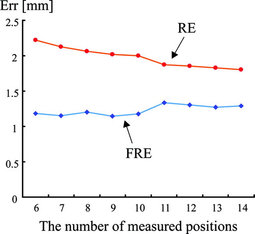
Table I. Standard deviations of the sensor's positional output. The sensor was placed 200 mm from the magnetic field generator, and the positional output was measured 600 times every 0.1 seconds for each of two positions: (i) with the sensor outside the bronchoscope; (ii) with the sensor inserted into the bronchoscope.
The following computer was used in the experiments: CPU Dual Intel Xeon 3.60 GHz, memory 2 GB, OS Microsoft Windows XP. The position sensor was inserted into the working channel of the bronchoscope. VB images were generated by a software-based volume-rendering method Citation[14] and used for image registration between the RB and VB images.
Discussion
As shown in , the SDs of the sensor's positional output were less than 0.1 mm for both sensor positions (outside and inside the bronchoscope). This shows that the output of the position sensor was very stable, with the SDs of the output being almost the same in both cases. From these results, the electromagnetic position sensor can be used to obtain the position of the tip of the bronchoscope.
shows the results for FRE and RE with the estimated transformation matrix . From these results, RE is reduced by increasing the number of positions used for computing
. However, even if 14 positions are used for computing
, RE is still greater than 1.5 mm. This means that the transformation between CT and the sensor output cannot be represented as a rigid transformation. Since the magnetic position sensor is readily affected by the presence of metal, the positions obtained by the sensor may not be the true positions of the sensor. By correcting for the influence of metallic objects on the magnetic field, a more accurate transformation matrix
can be obtained. To correct the sensor's output, non-rigid transformation will be necessary. This is very important for achieving accurate tracking, and will be included in our future work.
The experimental results show that we could track the bronchoscope continuously in real time (update rate: 0.4 seconds) (). shows tracking results of the proposed method at several positions of the bronchus (trachea, left main bronchus, and intermediate bronchus). From , the method using only sensor output could not estimate the twisting angle along the optical axis of the RB camera. However, as seen in and , the proposed method could track the bronchoscope's camera orientation satisfactorily. Taken together, these results confirm that image registration is useful for improving tracking accuracy. In fusing RB and VB images, the information concerning camera orientation is very important because the object appearing on the RB image must be reproduced at the same position on the VB image. In this regard, the proposed method is useful toward achieving a bronchoscope navigation system.
Figure 7. Tracking results of the proposed method. The left column shows scenes from the experiment; the right column shows the corresponding tracked results. [Color version available online]
![Figure 7. Tracking results of the proposed method. The left column shows scenes from the experiment; the right column shows the corresponding tracked results. [Color version available online]](/cms/asset/3d97c032-2d30-400b-95d6-d559d82fc225/icsu_a_175078_f0007_b.jpg)
Figure 8. Tracking results of the proposed method at several positions of the bronchus (trachea, left main bronchus, and intermediate bronchus). [Color version available online]
![Figure 8. Tracking results of the proposed method at several positions of the bronchus (trachea, left main bronchus, and intermediate bronchus). [Color version available online]](/cms/asset/7a4a2b8a-b435-44e3-b459-2f08520dc686/icsu_a_175078_f0008_b.jpg)
Figure 9. Tracking results of the method using only sensor output. [Color version available online]
![Figure 9. Tracking results of the method using only sensor output. [Color version available online]](/cms/asset/53cc6c75-8051-477b-8703-694f6bad58bf/icsu_a_175078_f0009_b.jpg)
The average computation time for updating camera position and orientation was approximately 0.4 seconds (=2.5 times per second) in the proposed method. This is much faster than with the previous method Citation[8–10], but is still not sufficient for an actual bronchoscope guidance system. To guide physicians smoothly, a rate of at least 10 frames per second is required. Accordingly, further improvement is needed to reduce computation time.
Conclusions
This paper has presented a method for tracking a bronchoscope by combining a position sensor and image registration. The fusion of an electromagnetic position sensor and image registration techniques enables us to track a bronchoscope in real time while maintaining tracking accuracy. Precise registration was achieved by performing image registration after rough estimation based on the position sensor's output. Future work includes (a) development of a method to correct for the influence of metal objects, (b) development of a method to compensate for sensor drift caused by breathing motion, (c) development of a method to compensate for quick movement of an RB, and (d) reduction of the computation time.
Acknowledgements
The authors would like to thank our colleagues for their useful suggestions and enlightening discussion. Parts of this research were supported by a Grant-In-Aid for Scientific Research from the Ministry of Education, the 21st Century COE program, a Grant-In-Aid for Scientific Research from the Japan Society for Promotion of Science, a Grant-In-Aid for Cancer Research from the Ministry of Health and Welfare of the Japanese Government, and a Special Research Aid from Kayamori Foundation of International Science Advancement.
Notes
Part of this research was previously presented at the 19th International Congress and Exhibition on Computer Assisted Radiology and Surgery (CARS 2005), held in Berlin, Germany, in June 2005.
References
- Vining DJ, Shitrin RY, Haponik EF, Liu K, Choplin RH. Virtual bronchoscopy. Proceedings of Radiological Society of North America Scientific Program (RSNA '94), Chicago, November 27-December 2, 1994; 261
- Geiger B, Kikinis R (1995) Simulation of endoscopy. Proceedings of First International Conference on Computer Vision, Virtual Reality and Robotics in Medicine (CVRMed '95), NiceFrance, April, 1995, N Ayache. Springer, Berlin, 277–281
- Rubin G, Beaulieu C, Argiro V, Ringl H, Norbash A, Feller J, Dake M, Jeffrey R, Napel S. Perspective volume rendering of CT and MR images: Applications for endoscopic imaging. Radiology 1996; 199(2)321–330
- Mori K, Urano A, Hasegawa J, Toriwaki J, Anno H, Katada K. Virtualized endoscope system — an application of virtual reality technology to diagnostic aid. IEICE Trans Inf Syst 1996; E79–D(6)809–819
- Hong L, Muraki S, Kaufman A, Bartz D, He T. Virtual voyage: interactive navigation in the human colon. Proceedings of the 24th Annual Conference on Computer Graphics and Interactive Techniques (SIGGRAPH 1997), Los Angeles, CA, 1997; 27–34
- Rogalla P, Terwisscha van Scheltinga J, Hamm B. Virtual Endoscopy and Related 3D Techniques. P Rogalla, J Terwisscha van Scheltinga, B Hamm. Springer, Berlin 2001
- Caramella D, Bartolozzi C. 3D Image Processing — Techniques and Clinical Application. D Caramella, C Bartolozzi. Springer, Berlin 2002
- Deguchi D, Mori K, Hasegawa J, Toriwaki J, Takabatake H, Natori H. Camera motion tracking of real endoscope using epipolar geometry analysis and CT derived bronchoscopic images. Proceedings of SPIE, San Diego, CA, February, 2002, 30–41, SPIE Vol. 4683
- Mori K, Deguchi D, Sugiyama J, Suenaga Y, Toriwaki J, Maurer CR, Jr, Takabatake H, Natori H. Tracking of a bronchoscope using epipolar geometry analysis and intensity-based image registration of real and virtual endoscopic images. Med Image Anal 2002, 6: 321–336
- Deguchi D, Mori K, Suenaga Y, Hasegawa J, Toriwaki J, Takabatake H, Natori H (2003) New image similarity measure for bronchoscope tracking based on image registration. Proceedings of 6th International Conference on Medical Image Computing and Computer Assisted Intervention (MICCAI 2003), MontrealCanada, November, 2003, RE Ellis, TM Peters. Springer, Berlin, 399–406, Part 1. Lecture Notes in Computer Science Vol 2878
- Horn BKP. Closed-form solution of absolute orientation using unit quaternions. J Optical Society of America A 1987; 4: 629–642
- Brent RP. Algorithms for Minimization Without Derivatives. Dover Publications. 2002
- Press WH, Teukolsky SA, Vetterling WT, Flannery BP. Numerical Recipes in C: The Art of Scientific Computing. Cambridge University Press. 1999; 321–336, Second Edition
- Mori K, Suenaga Y, Toriwaki J (2002) Fast volume rendering based on software optimization using multimedia instructions on PC platform. Computer Assisted Radiology and Surgery. Proceedings of the 16th International Congress and Exhibition (CARS 2002), Paris, 2002, June, HU Lemke, MW Vannier, K Inamura, AG Farman, K Doi, JHC Reiber. Springer, Berlin, 467–472