Abstract
Objective: The purpose of this study was to investigate the relationship of cup position versus pelvic lateral tilt and inclination. While computer assisted navigation systems use only the pelvic frontal plane for cup placement, it is important to realize the effect of leg length differences or increased pelvic inclination, i.e., caused by contracted hip flexors.
Materials and Methods: Using a sawbone model of the pelvis, cup position measurements were performed with different pelvic inclination and lateral tilt angles. The measured values were compared with outcome variables from a mathematical model. A computer program was developed to perform a reverse calculation to verify the mathematical model.
Results: The mathematical model proved correct in the sawbone pelvis experiment. The cup position changed from 15° anteversion in 0° pelvic inclination to 0.5° retroversion in 15° pelvic inclination. Regardless of pelvic inclination, the vertical cup projection stayed in a safe range of 37–47°. Leg length differences greater than 3 cm have significant effects on the positioning of acetabular cups in the frontal plane.
Conclusions: Using computer navigation, it is possible to determine pelvic inclination and lateral tilt during an operation by calculating the angular difference between the anatomic frontal plane and the “real world” frontal plane (i.e., the OR table). This method may be helpful in increasing the accuracy of positioning of acetabular cups.
Introduction
In total hip arthroplasty, exact implant positioning, correct implant type/size, and correct cementing technique are essential to obtain good long-term results and avoid premature implant failure, loosening or dislocation.
A wide range of experiments and studies has been conducted to verify the long-term results of total hip surgeries. A plurality of methods have been developed to evaluate the changes in socket position from radiographs with patients in varying pelvis positions in order to detect implant loosening or determine the anteversion angle of a cup implant Citation[1–3]. These mostly retrospective studies calculated the cup position with regard to anatomical landmarks of the pelvis.
To achieve greater accuracy in the implantation of total hip prostheses, especially in cases with anatomical variations such as dysplastic hips, preoperative planning and intraoperative determination of implant position can be of enormous help Citation[4], Citation[5].
Computers are playing an increasing role in the planning and execution of orthopedic surgeries Citation[6–8], and computer-assisted navigation systems can reduce the number of outliers, i.e., cups implanted in unfavorable positions outside the “safe range” Citation[9], Citation[10]. They can be especially useful in dysplastic hips and other difficult cases (e.g., post-traumatic patients) Citation[11]. Mechanical navigation tools basically consist of a set of rods attached to the cup impactor. These tools necessitate the alignment of the rods against certain landmarks (i.e., the OR table). With a variable patient position during the operation and only limited visibility of the operative site, the final results may vary greatly, causing complications of the implant appositions Citation[12].
Aligning a mechanical tool on a patient in the supine position using the OR table for reference and not using the known landmarks to define the patient's pelvis frontal plane is in essence the method proposed in this paper. Problems with the handling of tools and the limitations on visibility have led to computer-assisted navigation systems. These systems consist of a computer, an infrared camera with special recognizable infrared tools, and reference frames (patient trackers) that are attached to the patient during surgery. Different imaging modalities such as CT or fluoroscopy can be used in conjunction with navigation, and implants or tools can be projected over previously acquired CT or fluoroscopy images. The trajectories of various tools (e.g., the reamer or impactor) are displayed on the computer screen relative to previously defined landmarks without imaging. All current computer-assisted cup navigation systems only define the cup position relative to the assumed human frontal plane consisting of the two anterior iliac spines and the pubic tubercle, unlike conventional alignment methods in the OR.
The ideal cup inclination angle should be approximately 45°, whereas the desired anteversion angle is 15–20°. These angles are measured assuming that the physiological frontal plane of the pelvis, defined by a triangle consisting of the pubic symphysis and both anterior superior iliac spines, is identical with the vertical “real world” frontal plane. However, arthritic, rheumatic and neurological diseases can lead to contracture of the hip flexors and increased pelvic inclination Citation[13]. The patient's posture will therefore change, with the pelvis increasingly inclining forward. Patients with hip arthritis frequently complain of pain in their lower back region due to their growing hyperlordosis, which compensates for the anteriorly inclined pelvis. The contracture of the hip flexors is often irreversible, even after a total hip replacement, and this aspect is not always taken into full account during total hip replacement surgery.
Over the past several years, various navigation systems and methods have been developed specifically for use in spine surgery and total joint replacement Citation[10–12]. Since computer navigation systems calculate the actual intraoperative cup position in relation to the patient's frontal plane, as defined by the left and right anterior superior spines and the pubic tubercle, pelvic inclination as a result of hip-flexion contractures is not considered. This can lead to an acetabular cup position that encourages dislocation, limited range of motion and early loosening.
Several authors have described the influence of pelvic inclination on the postoperative radiographic determination of acetabular cup position Citation[5], Citation[6], Citation[8]. Surgeons using navigation systems must be provided with data on the correct cup placement for certain variations of pelvic inclination and lateral tilt – inclination being defined as the ventral movement of the pelvis, while the pelvic lateral tilt describes the movement of the pelvis in the frontal plane, as is the case in leg length differences, for example.
The aim of the present study is to develop a navigated total hip replacement technique in order to improve the accuracy of acetabular cup positioning and thereby ensure a fully functional total hip replacement.
Materials and methods
Experimental setting
A sawbone model of the pelvis was mounted on a camera stand to simulate the influence of different pelvic positions on the projection of the implanted acetabular cup. The frontal plane was visualized by connecting three metal rods which were fixed on the pubic tubercle and both anterior superior iliac spines ().
Figure 1. Sawbone pelvis model: Attached plumb line, pelvis frontal plane, and acetabular cup with rod indicating its inclination and anteversion angles.

To optimize the cup position measurements, a screw 25 cm in length was placed into the center of the acetabular cup. This allowed the determination of the inclination and anteversion angle of the cup () by measuring the angles between the screw and the frontal/sagittal planes.
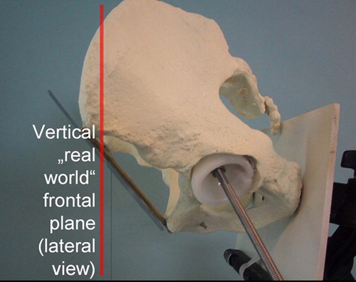
Figure 2. Vertical plane of the sawbone model.
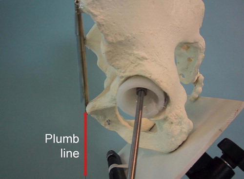
Figure 3. Visualized frontal plane of the pelvis.
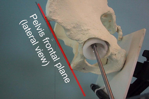
Figure 4. Increasing pelvic inclination leading to a change in anteversion.
A weight-loaded thread was attached to one anterior superior iliac spine to form the plumb line (), in order to measure the angle between the vertical and the previously defined pelvic frontal plane (), resulting in the value for pelvic inclination.
A difference in leg length in the range 0–5 cm was simulated by laterally tilting the pelvis with either the right or left hip upwards or downwards. The lateral tilt angle was defined by positive values for clockwise rotation of the pelvis in the frontal plane from the patient's point of view, i.e., the left hip rotating upwards and the right hip downwards. Negative pelvic lateral tilt values were originated in a counter-clockwise rotation of the hip. The lateral tilt angle was calculated using a formula (Lateral tilt angle = arcsin (leg length difference/distance between both acetabular centers)).
Implantation of the acetabular cup
A hemispheric acetabular cup was glued into the left side of the sawbone model at a position with 45° of inclination and 20° of anteversion. For different pelvic inclination and lateral tilt angles two variables were determined:
The projected cup inclination angle, i.e., the cup inclination angle projected onto the vertical “real world” frontal plane formed by a virtual triangle connecting both anterior superior iliac spines and the plumb line.
The cup anteversion angle, i.e., the angle between the long screw protruding from the center of the cup and the plumb line in the lateral pelvis view.
The values measured manually, using a goniometer, were compared with the mathematical model we applied to simulate and describe our findings (). For increased accuracy, the goniometer angle measurements were performed repeatedly in 5° increments by the first author only.
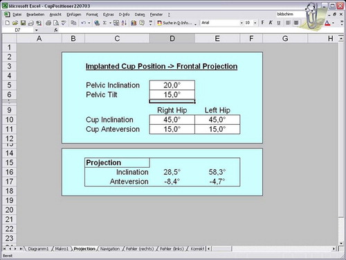
The first step is a description of the position of the pelvis using lateral tilt and inclination (angle α). From the leg length difference Δd and the distance from the center of the joints, the angle α = arcsin (Δd / b) was calculated. Using the navigation system, the angle β was determined as the tilt in the frontal plane. The axes of a right-angled coordinate system were related to the body axes. The x-axis points to the right with reference to the patient, the y-axis points ventrally, and the z-axis cranially. The computer program was developed using the Microsoft Excel program () performing trigonometrical matrix calculations in order to implement the mathematical model.
Figure 5. Microsoft Excel program screenshot showing the results of calculating the projected cup positions in a pelvis with 20° of inclination and left hip elevated 15°.
The cup is represented by the vector P = (0, 0, − 1). The following calculation is an example for the right hip. Without consideration of pelvic tilt, the position of the cup P′ with 45° inclination and 15° anteversion is as follows:
The resultant angles for inclination and antetorsion are then calculated:
Pelvic tilt leads to an incorrect positioning of the acetabular cup. The final position P″ is determined by the inclination and tilt of the pelvis:
Using a navigation system, the inverse situation is of special interest. The cup needs to be implanted in an optimal position while P″ represents the desired position using a reverse calculation:The cup angles of inclination and anteversion, projected to the vertical “real world” frontal plane (parallel to the plane formed by the plumb line and both anterior superior iliac spines) were measured manually and compared with the values generated by the computer. To achieve a correct cup position in relation to the “real world” coordinate system, a reverse calculation of the above process was used to obtain ideal cup implantation angles with regard to the pelvic plane as is used by current computer navigation systems.
Results
The applied mathematical model was constantly verified in different pelvis positions and errors corrected until the results were completely identical with the manual angle measurements.
With 20° decreasing pelvic inclination the projected cup inclination decreased from 45° to 37°, while the projected cup anteversion increased from 15° to 31°. Regardless of the pelvic inclination, the projected cup inclination stayed within a safe range of 37–47° (, ). With 45° increasing pelvic inclination the projected cup inclination first increased from 45° to 47° (15° pelvic inclination) and then decreased to 39°, and the projected cup anteversion increased from 15° to 29°.
Figure 6. Acetabular cup inclination in relation to pelvic inclination. Values are given in degrees.
Table I. Projected implant positions in the vertical plane with acetabular cup position of 45° inclination / 15° anteversion with regard to the pelvis frontal plane and different grades of pelvic inclination.
and and show the results for an acetabular cup which was placed in the standard position of 45° inclination and 15° anteversion using the pelvic frontal plane (i.e., both anterior superior iliac spines and the pubic tubercle) as the reference coordinate system.
Figure 7. Acetabular cup anteversion in relation to pelvic inclination. Values are given in degrees.
Small changes in pelvic inclination have a significant effect on the vertical projection of the acetabular cup anteversion (). shows the proposed acetabular cup implant position for different degrees of pelvic inclination, all resulting in a projected cup position of 45° inclination and 15° anteversion (measured in the “real world” frontal plane).
Table II. Calculated cup positions in relation to the pelvis frontal plane for a projection of 45° inclination / 15° anteversion in the vertical frontal plane for different degrees of pelvic inclination.
Leg length differences smaller than 3 cm have tolerable effects on the orientation of the pelvis in the frontal plane. With leg length differences increasing to 5 cm, the pelvic lateral tilt angle enlarged to 19°. The resulting effect of leg length differences on pelvic lateral tilt in the frontal plane can be seen in .
Table III. Influence of leg length difference on pelvic lateral tilt angle.
With acetabular cups being implanted on both sides with 45° of inclination and 15° of anteversion – relative to the pelvis frontal plane – an elevation of the left hip side in a clockwise rotation from the patient's point of view resulted in a positive pelvic lateral tilt angle.
With increasing pelvic lateral tilt the differences between the elevated and contralateral sides for hip cup inclination and anterversion increased (). In neutral pelvic inclination with pelvic lateral tilts of 15–20° the elevated left hip cup showed an inclination and anteversion approximately twice as high as that on the contralateral side. With 15° of pelvic inclination the hip cup anterversion was comparable for the elevated left hip and the contralateral side. shows the effect on the projected cup position with different degrees of pelvic lateral tilt in the frontal plane and various degrees of pelvic inclination.
Table IV. Effect of pelvic lateral tilt and inclination on projected implant positions in the vertical plane with bilateral acetabular cup positions of 45° inclination / 15° anteversion with regard to the pelvis frontal plane.
Discussion
Current clinical results and computed simulations indicate an ideal acetabular cup position at 35–55° of inclination and 10–20° of anteversion Citation[14], Citation[15]. An inclination below 45° will decrease flexion and abduction, whereas higher angles will decrease adduction and rotation. Femoral and acetabular anteversion will increase flexion and decrease extension Citation[16]. Cup anteversion angles above 20° combined with cup inclination angles greater than 45° significantly limit internal and external rotation, particularly for hip flexion greater than 60° Citation[17]. Anatomic studies in cadavers have revealed an average anatomic acetabular anteversion angle of 21.3° in females and 18.5° in males Citation[18]. Besides limiting the range of motion, incorrect cup positioning can cause faster loosening, pelvic osteolysis, implant failure and a tendency to dislocation if implanted in a position outside the above-mentioned ranges Citation[19], Citation[20]. Factors contributing to impingement between acetabular and femoral components include excessive cup anteversion combined with posterior positioning of the extended rim and femoral components with relatively small head-to-neck diameter ratios Citation[21].
In the standing posture, the right and left superior anterior iliac spines and pubic tubercle align with the vertical frontal plane as well as with the promontory of the sacrum and the acetabular center Citation[22]. The pelvic frontal plane of healthy individuals changes slightly during walking, as kinematic investigations have shown Citation[23]. Non-alignment of the pelvic frontal plane in relation to the vertical frontal plane can arise for various reasons. Gait laboratory trials have revealed that “even at an early stage of hip osteoarthritis, joint degeneration was compensated by an increase in pelvis motion and muscle power generation or absorption modifications in other lower limb joints” Citation[24]. Using gas-rate sensors in gait tests, healthy individuals were distinguished from patients with hip arthritis by observation of the waveform on the frontal plane and the ratio of the rotational angle on the sagittal plane to that on the frontal plane Citation[25].
It is known that pelvic inclination can cause important differences in the interpretation of the acetabular cup position depending on the radiographic method employed. Some authors recommend measurement of the inclination of the acetabular cup in erect posture radiographs Citation[26]. Anda et al. Citation[27] measured pelvic inclination with radiographs and CT scans and found no difference between patients in the supine and upright positions. Clinical inclinometer measurements have proven to be unreliable and invalid Citation[28]. The standard method for measuring sacral inclination in order to determine pelvic inclination is by radiograph of the patient in the standing position.
In patients with non-correctable or great pelvic inclination, using the conventional method, i.e., cup alignment in relation to the patient's anatomic frontal plane, the “real world” frontal cup position (the position projected onto the vertical plane) will be different from the planned position. Computer-assisted navigation can be deceiving. In the present study, the implanted cups demonstrated a tendency towards retroversion with increasing pelvic inclination. Our results show that in a patient with 20° of ventral pelvic inclination the target values for the computer navigation system should be 37° inclination and 31° anteversion in order to achieve a cup position of 45° inclination and 15° anteversion.
Leg length inequality after total hip surgery is not a common problem. Woolsen et al. Citation[29] evaluated 351 patients (408 hips) and found that 97% of the patients had a postoperative leg length discrepancy of less than 1 cm, while 86 % had a leg length difference of 6 mm (a quarter of an inch) or less. Our computer program also calculated the consequences of the acetabular cup position in relation to leg length differences that might be of importance for preoperative planning. An assumed leg length difference of 1 cm, for example, will result in a negligible pelvic lateral tilt angle of 4° – given an average distance of both acetabular centers of 15 cm. In dysplastic hips, however, larger leg length differences can occur due to a high dysplastic hip center. A leg length difference of 5 cm will lead to a pelvic lateral tilt angle of approximately 20°. If both acetabular cups had been implanted with 45° inclination and 15° anteversion, the actual projected cup positions in the vertical frontal plane would be 26° inclination /25° anteversion for the shorter leg / lower pelvis side, and 65° inclination /12° anteversion for the longer leg / higher pelvis side. Adding a pelvic inclination of 20° to a leg length difference of 5 cm, the cup position projected onto the vertical frontal plane will be 24° inclination / 10° retroversion for the shorter leg /lower pelvis side, and 63° inclination /5° retroversion for the longer leg / higher pelvis side. The differences, especially for the anteversion angles, can be significant and must be taken into account regarding the given risk of dislocation.
In conclusion, we found that pelvic inclination and leg length differences are important factors in the accuracy of acetabular cup placement that must not be neglected when planning a hip cup replacement. The presented computer program is able to convert the acetabular cup position from the pelvic frontal plane coordinate system, as defined by the left and right anterior superior iliac spine and the pubic tubercle, into the projected acetabular cup position with the vertical “real world” frontal plane as the reference coordinate system. Leg length differences causing pelvic lateral tilt and inclination are considered in the calculation. It is also possible to perform a reverse position calculation, i.e., the computation with a target value of 45° inclination and 15° anteversion for the projected cup position in the vertical frontal plane, given certain values for pelvic lateral tilt and inclination, resulting in a suggested calculated cup position in relation to the pelvic frontal plane. These values can be useful when using a computed navigation system that allows accurate implant placement with regard to the pelvis plane.
Pelvic lateral tilt and inclination should be determined preoperatively from radiographs for accurate planning. Using computed navigation, it is possible to determine pelvic lateral tilt during an operation by calculating the angular difference between the anatomic frontal plane (both anterior superior iliac spines and the pubic tubercle) and the “real” frontal plane (represented by the OR table, for example). This functionality may be included in commercially available computer systems to improve the accuracy of hip cup implantation.
Related Research Data
References
- Siebenrock KA, Kalbermatten DF, Ganz R. Effect of pelvic lateral tilt on acetabular retroversion: a study of pelves from cadavers. Clin Orthop 2003, 407: 241–248
- Inaoka H, Ishida A, Fukuoka Y, Suzuki K, Matsubara M. Pose estimation of artificial hip joint using a single radiographic projection. Med Biol Eng Comput 2003; 41(1)94–100
- Valstar ER, Spoor CW, Nelissen RG, Rozing PM. Roentgen stereophotogrammetric analysis of metal-backed hemispherical cups without markers. J Orthop Res 1997; 15(6)869–873
- Egglie S, Pisan M, Müller ME. The value of preoperative planning for total hip arthroplasty. J Bone Joint Surg Br 1998; 80(3)382–390
- De Thomasson E, Mazel C, Guingand O, Terracher R. Value of preoperative planning in total hip arthroplasty. Rev Chir Orthop Reparatrice Appar Mot 2002; 88(3)229–235
- Jerosch J, Weipert A, Hanusek S, Schneppenheim M. Movement mapping as dynamic preoperative surgical planning in total hip replacement. A precondition to navigation?. Arch Orthop Trauma Surg 2002; 122(6)342–345
- Yoshimine F, Ginbayashi K. A mathematical formula to calculate the theroretical range of motion for total hip replacment. J Biomech 2002; 35(7)989–993
- Sugano N, Ohzono K, Nishii T, Haraguchi K, Sakai T, Ochi T. Computed-tomography-based computer preoperative planning for total hip arthroplasty. Comput Aided Surg 1998; 3(6)320–324
- Leenders T, Vandevelde D, Mahieu G, Nuyts R. Reduction in variability of acetabular cup abduction using computer assisted surgery: a prospective and randomized study. Comput Aided Surg 2002; 7(2)99–106
- Bernsmann K, Langlotz U, Ansari B, Wiese M. Computer-assisted navigated cup placement of different cup types in hip arthroplasty—a randomised controlled trial. Z Orthop Ihre Grenzgeb 2001; 139(6)512–517
- Haaker R, Tiedjen K, Rubenthaler F, Stockheim M. Computer- assisted navigated cup placement and secondary dysplastic hips. Z Orthop Ihre Grenzgeb 2003; 141(1)105–111
- DiGioia AM, Jaramaz B, Blackwell M, Simon DA, Morgan F, Moody JE, Nikou C, Clogan BD, Aston CA, Labarca RS, Kischell E, Kanade T. The Otto Aufranc Award. Image guided navigation system to measure intraoperatively acetabular implant alignment. Clin Orthop 1998, 335: 8–22
- Hurwitz DE, Hulet CH, Andriacchi TP, Rosenberg AG, Galante JO. Gait compensations in patients with osteoarthritis of the hip and their relationship to pain and passive hip motion. J Orthop Res 1997; 15(4)629–635
- Bader R, Steinhauser E, Gradinger R, Willmann G, Mittelmeier W. Computer-based motion simulation of total hip prostheses with ceramic-on-ceramic wear couple. Analysis of implant design and orientation as influence parameters. Z Orthop Ihre Grenzgeb 2002; 140(3)310–316
- Hirakawa K, Mitsugi N, Koshino T, Saito T, Hirasawa Y, Kubo T. Effect of acetabular cup position and orientation in cemented total hip arthroplasty. Clin Orthop 2001, 388: 135–142
- D'Lima DD, Urquhart AG, Buehler KO, Walker RH, Colwell CW Jr. The effect of the orientation of the acetabular and femoral components on the range of motion of the hip at different head-neck ratios. J Bone Joint Surg Am 2000; 82-A(11)1671–1672
- Kummer FJ, Shah S, Iyer S, DiCesare PE. The effect of acetabular cup orientations on limiting hip rotation. J Arthroplasty 1999; 14(4)509–513
- Maruyama M, Feinberg JR, Capello WN, D'Antonio JA. The Frank Stinchfield Award: Morphologic features of the acetabulum and femur: anteversion angle and implant positioning. Clin Orthop 2001, 393: 52–65
- Barrack RL. Dislocation after total hip arthroplasty: implant design and orientation. J Am Acad Orthop Surg 2003; 11(2)89–99
- Jolles BM, Zangger P, Leyvraz PF. Factors predisposing to dislocation after primary total hip arthroplasty: a multivariant analysis. J Arthroplasty 2002; 17(3)282–288
- Yamaguchi M, Akisue T, Bauer TW, Hashimoto Y. The spatial location of impingement in total hip arthroplasty. J Arthroplasty 2000; 15(3)305–313
- Hiramato Y. Morphometrical features of the pelvis in standing posture. Kaibogaku Zasshi 2000; 75(2)223–230
- Vanneuville G, Poumarat G, Guillot M, Garcier JM, Terver S, Duclos F, Vacheron JJ. Determination of the position of the pelvic girdle using surface markers. Surg Radiol Anat 1997; 19(5)341–343
- Watelain E, Dujardin F, Babier F, Dubois D, Allard P. Pelvic and lower limb compensatory actions of subjects in an early stage of hip osteoarthritis. Arch Phys Med Rehabil 2001; 82(12)1705–1711
- Kawate K, Ohneda Y, Kakihana T, Tamai S. Assessment of limp in patients with coxarthrosis – three dimensional measurement of the pelvic rotation. Nippon Seikeigeka Gakkai Zasshi 1992; 66(7)643–656
- Hoikka V, Ylikoski M, Eskola A, Santavirta S. Inclination of the acetabular cup in erect posture radiographs. Orthopedics 1993; 16(12)1321–1323
- Anda S, Svenningsen S, Grontvedt T, Benum P. Pelvic inclination and spatial orientation of the acetabulum. A radiographic, computer tomographic and clinical investigation. Acta Radiol 1990; 31(4)389–394
- Bierma-Zeinstra SM, van Gool JJ, Bernsen RM, Njoo KH. Measuring the sacral inclination angle in clinical practice: Is there an alternative to radiographs?. J Manipulative Physiol Ther 2002; 25(2)139–140
- Woolsen ST, Hartford JM, Sawyer A. Results of a method of leg-length equalization for patients undergoing primary total hip replacement. J Arthroplasty 1999; 14(2)159–164