Abstract
For over 20 years, interventional methods have improved the outcomes of patients with cardiovascular disease. However, these procedures require an intricate combination of visual and tactile feedback and extensive training. In this paper, we describe a series of novel approaches that have led to the development of a high-fidelity simulation system for interventional neuroradiology. In particular, we focus on a new approach for real-time deformation of devices such as catheters and guidewires during navigation inside complex vascular networks. This approach combines a real-time incremental Finite Element Model (FEM), an optimization strategy based on substructure decomposition, and a new method for handling collision response in situations where the number of contact points is very large. We also briefly describe other aspects of the simulation system, from patient-specific segmentation to the simulation of contrast agent propagation and fast volume-rendering techniques for generating synthetic X-ray images in real time. Although currently targeted at stroke therapy, our results are applicable to the simulation of any interventional radiology procedure.
Introduction
Stroke, the clinical manifestation of cerebrovascular disease, is the third leading cause of death in the United States. Each year, more than 700,000 strokes result in over 200,000 deaths Citation[1]. Ischemic strokes can now be treated using interventional neuroradiologic therapies which rely on the insertion and navigation of catheters and guidewires through a complex network of arteries to restore blood flow. Once the site of occlusion as been reached, localized therapy can be administered. This minimally invasive procedure is done under fluoroscopic imaging, without direct vision of the operating field. Because the treatment is delivered directly within the closed brain, using only image-based guidance, dedicated skill in instrument navigation and a thorough understanding of vascular anatomy are critical to avoid devastating complications which could result from poor visualization or poor technique.
Using simulation techniques, a significant number of practice cases could be performed even in the absence of actual clinical cases, enabling a certain level of proficiency to be attained before practicing on patients. This was the basis for a recent decision by the FDA requiring all physicians who wish to treat carotid disease using catheter-based techniques to train to proficiency before performing high-risk procedures in the cerebral circulation. However, while most publications in the field of medical simulation have addressed issues related to laparoscopic training, few aspects of interventional radiology simulation have been explored. Aside from modeling the soft tissue deformation of arteries, other complex problems need to be solved to enable real-time, accurate simulation of such procedures. This paper concerns the simulation of non-linear deformations of wire-like structures under a large number of non-holonomic constraints, and the definition of such constraints to confine the catheter inside the vascular network. We also briefly mention other results in the areas of real-time fluid flow computation, real-time synthetic X-ray rendering, and patient-specific segmentation. Although some of these problems have been addressed in previous work Citation[2–5], in particular in the areas of visualization and catheter modeling, many challenging problems remain, especially when seeking a higher level of fidelity and accuracy in the simulation while maintaining real-time computation performance. In this paper we address the important problem of deformation of catheters or guidewires under a very large number of inequality constraints, as occurs during navigation inside the vascular system. We also describe several new approaches to rendering, blood-flow and contrast agent modeling that enable high-fidelity simulation. Finally, we present a methodology for generating a multi-level representation of the vascular network that can allow patient-specific data to be used in the simulator while providing a description specific to each module of the simulator.
Modeling of wire-like structures
To control the motion of a catheter or guidewire within the vascular network, the physician can only push, pull or twist the proximal end of the device. Since such devices are constrained inside the patient's vasculature, it is the combination of input forces and contact forces that allow them to be moved toward a target. The main characteristics of wire-like structures that current models attempt to capture include geometric non-linearities, high tensile strength and low resistance to bending. We previously proposed a multibody dynamics model Citation[6] where a set of rigid elements are connected using spherical joints Citation[2], thus mimicking the basic behavior of such devices (limited elongation, high resistance to torsion, and variable resistance to bending). Another interesting approach to modeling wire-like structures was introduced by Lenoir et al. Citation[7]. In this model, a one-dimensional dynamic spline model is used, providing a continuous representation. Different constraints can be defined to control the model, such as sliding through fixed locations. Although real-time computation is possible, this model does not incorporate torsional energy terms. A virtual catheter model, based on a linear elasticity Finite Element representation, was introduced by Nowinski and Chui Citation[3], using a set of finite beam elements. The choice of beam elements for the catheter model is natural since beam equations account for cross-sectional area, cross-section moment of inertia, and polar moment of inertia, allowing solid and hollow devices of various cross-sectional geometries and mechanical properties to be modeled. The main issue with such a linear model is its inability to represent the large geometric non-linearities that occur during navigation of the catheter or guidewire within the vascular network.
Another approach also directly targeted at virtual catheter or guidewire modeling was proposed by Alderliesten Citation[5]. In this model, only bending energies are computed, assuming no elongation and perfect torque control. The model has characteristics similar to those of a multi-body dynamics model, but integrates more complex bending energies, as well as local springs for describing the intrinsic curvature of the catheter. Contact with the vessel walls is modeled using a potential distribution that represents the gradient of the (elastic) vessel-wall energy. The potential distribution is zero inside the lumen of the vessel and non-zero outside. Although based on a more ad hoc representation, a good level of accuracy is obtained using this model. The main drawbacks are the way in which collision response is handled during contact with the vessel walls, and the fact that computation times are incompatible with real-time requirements.
To improve the accuracy of previously proposed models and handle geometric non-linearities while maintaining real-time computation, we have developed a new mathematical representation based on three-dimensional beam theory, combined with an incremental approach that allows for highly non-linear behavior using a linear model, thus guaranteeing real-time performance. Further optimizations based on substructure decomposition are introduced. Finally, a new method for correctly handling contact response in complex situations where a large number of nodes are subject to non-holonomic constraints is presented.
Incremental finite element model
To model the deformation of a catheter, guidewire, or any solid body whose geometry and mechanical characteristics are similar to those of a wire, rod or beam, we use a representation based on three-dimensional beam theory Citation[8], where the elementary stiffness matrix is a 12 × 12 symmetric matrix that relates angular and spatial positions of each end of a beam element to the forces and torques applied to them:
 with G = E/(2*(1 + ν)) where E is the Young's modulus and ν the Poisson's ratio; A is the cross-sectional area of the beam, and l its length; Iy and Iz are cross-section moments of inertia; Φy and Φz represent shear deformation parameters and are defined as Φy = 12 EIz/G Asyl2 and Φz = 12 EIy/G Aszl2 with Asy and Asz the shear area in the the y and z directions.
To determine the stiffness property of the complete structure, a common reference frame must be established for all unassembled structural elements so that all displacements and their corresponding forces will be referred to a common (global) coordinate system. As the stiffness matrix is initially calculated in local coordinates, oriented along the frame of the first node of the beam (to minimize the computing effort), it is necessary to introduce transformation matrices changing the frame of reference from a local to a global coordinate system. The first step in deriving such a transformation is to obtain a matrix relationship between the element displacement
in the local coordinate system and the element displacement u in the global coordinates (see ). This relationship is expressed by the matrix equation
where Λ is a matrix of coefficients obtained from the direction cosines of angles between the local and global coordinate systems and
reflects the initial configuration of the beam.
Figure 1. Initial (blue) and deformed (red) configurations. (a) The initial configuration of a catheter could be curved. Thus, for each beam, we store an initial displacement based on the position of the tip node in the local frame of the base node. (b) Actual deformations can always be measured locally in the local reference frame using
. Displacements from initial configuration to deformed configuration are measured using u in the global reference frame and by
in the local frame. [Color version available online.]
![Figure 1. Initial (blue) and deformed (red) configurations. (a) The initial configuration of a catheter could be curved. Thus, for each beam, we store an initial displacement based on the position of the tip node in the local frame of the base node. (b) Actual deformations can always be measured locally in the local reference frame using . Displacements from initial configuration to deformed configuration are measured using u in the global reference frame and by in the local frame. [Color version available online.]](/cms/asset/7657add8-0eef-4d76-a5a0-b0aaf589a97f/icsu_a_209006_f0001_b.jpg)
As the resulting virtual work must be independent of the coordinate system, it follows that
By use of previous equations, the following element force-displacement equation is obtained in global coordinates:
To model a wire-like structure such as a catheter or guidewire, we serially link a series of beam elements (see ). As a result, for the entire structure describing a catheter or guidewire, the global stiffness matrix K is computed by summing the contributions of each element, thus leading to the following equilibrium equation:where K is a band matrix due to the serial structure of the model (one node is only shared by one or two elements) and u represents a column matrix of displacements corresponding to external forces f.
The matrix K is singular unless some displacements are prescribed through boundary conditions. Such boundary conditions are naturally specified by setting the first node (base node) of the device model to a particular translation or rotation imposed by the user. The motion and deformation of the model is then entirely determined by its set displacement at the base node and the forces f applied at different nodes as the result of contacts with the vessel wall (see Contact response section below). There is, however, one main drawback in using such a model directly: it is linear, and as such cannot represent the geometric non-linearities that a typical wire-like object exhibits. Therefore, we propose to update Λ for each beam element, and at every time step, by using the solution obtained at the previous time step. The new set of local stiffness matrices are then assembled in [K]. This approach is different than other methods such as the co-rotational method Citation[9] or other techniques that remove the rigid body transformation from a given configuration to remain in the linear domain Citation[10]. Here, we do not use the initial configuration as the reference state, but rather the previously computed solution. By controlling when each new K is to be computed, we can ensure that we remain in the linear domain for each incremental step, leading to a correct, global deformation.
When using this approach, however, the model could exhibit inelastic behavior, i.e., in the absence of forces or torques, the model would only return to the previous state, not the reference configuration. We overcome this problem by computing an elastic force on each beam, defined as follows:
with 0 < γ ≤ 1. This force is added to the external forces f in the global coordinate system
before solving the linear system, and can be shown to act as a damping force, where γ relates to the damping coefficient of the model.
To simulate accurately a device such as a guidewire or catheter in the context of interventional neuroradiology, we need to discretize the device using a large number (from 100 to 200) of beam elements. Although solving linear systems with approximately 1,000 unknowns can be done in real time using iterative methods, when integrating non-holonomic constraints, real-time computation on a single-processor workstation is no longer possible. To improve speed and accurately handle collision response, we propose the following optimizations.
Optimization using substructures analysis
The inverse matrix K−1 of the stiffness matrix gives a measure of the flexibility of the model. For a force applied on one node, the induced displacement of all nodes can be obtained through the flexibility matrix. Using the flexibility representation of the behavior of the wire-like object also provides a means to determine the mechanical coupling that exists between nodes. As seen previously, by using an incremental approach, the wire-like model is described by a linear relation between forces and displacements that changes at every time step. To optimize computational speed, we propose an assembling method of inverted mechanics which makes it unnecessary to assemble the mechanical properties of the devices in K, therefore precluding the need to compute the whole flexibility matrix K−1.
Principle of matrix substructure analysis
Without loss of generality, let us assume that the nodes of the wire-like model have been ordered with the boundary (b) nodes first, followed by the internal (i) nodes. Using this ordering, we can write the linear system describing the model as a block matrix system:
One can solve the system this way:
Previous work in the field on real-time deformable models uses this result Citation[11] to reduce computation when fi = 0 or only ub needs to be computed. Such approaches are often referred as condensation methods. Here, we use the inverted system in a different way. We decompose the resolution of the entire system in three steps:
and
Boundary fixation by accumulation
We start by considering that the first node (for instance, the base node) is an internal node, and that all other nodes are on the boundary. As the only boundary node directly connected to the first node is the second node, we can compute the following:
These equations refer to the first step of the substructure analysis (see also ), with facc the accumulation force that contains the reaction force on the boundary due to internal force f1. We also compute the new apparent stiffness of boundary node 2 using
Figure 2. (a) Setting boundary conditions: the object is split into a series of substructures, and local displacements and force facc are computed after constraining the boundary node of each substructure. (b) Relaxing boundary conditions: correction displacements
are applied recursively, starting from node N, at each internal node of each substructure.
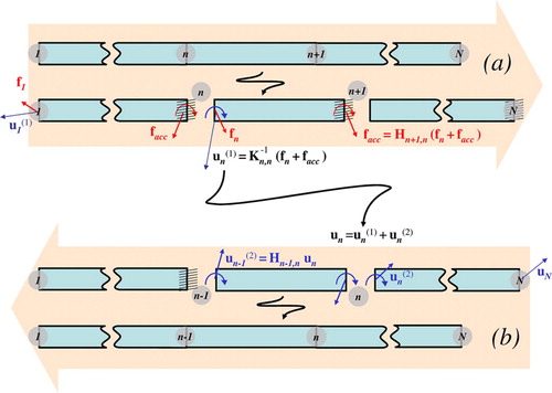
Then, as the influence of internal node 1 has been applied to boundary node 2, we repeat this scheme by considering node 2 as an internal node, and nodes [3 … N] as boundary nodes, and so on. More generally, for a step where node n is considered to be an internal node, node n + 1 will be the only boundary node directly connected to it, thereby leading to the following set of equations:
Boundary relaxation by accumulation
When we reach the last node N, facc represents the reaction force on N due to the force on all internal nodes (i.e., all the nodes except the last one). From this we can compute the motion of the boundary, according to the boundary relaxation step (see ):
We can now evaluate the motion on the internal nodes due to the motion of the boundary last node N:
Flexibility assembling by accumulation
In order to compute the total displacement of N − 1, we use the third step of the substructure analysis:
Using flexibility assembling, we can compute the value of K−1 for the node N − 1:
When N − 1 is computed, we consider it as the boundary of all previous nodes. We then compute N − 2, and repeat until all nodes are processed.
Algorithm 1: System solving using substructure analysis
Contact response
Another important problem in simulating catheter or guidewire navigation is solving the contacts between the virtual device and the vessels wall. Because sliding occurs at the point of contact, Lagrange multiplier techniques, simple penalty forces or quadratic programming approaches will not constrain the flexible body properly. To solve this problem, we compute the local compliance of the node in the contact space defined by nα, where nα is the normal at contact point. The local compliance of the contact α, at node n, is
The computation of Wα, α is very efficient, since (K−1) n, n is already known from . The problem of multiple sliding contact can be solved using
Algorithm 2: Flexibility computation using substructure analysis
a Gauss-Seidel-like algorithm Citation[12]. Considering a contact α, among m instantaneous contacts, one can write the behavior of the model in contact space:where [Wα, β] is a compliance matrix that models the coupling between contact points α and β. For each contact α, this method solves the contact equations by considering the others contact points (α ≠ β) as “frozen”. The new value of fα is given by solving the Signorini's law on this contact:
Consider the current state of a contact (δα, fα). By removing the current contribution of the contact force fα, we obtain a new value of δα that we call the free status of the contact (). If the status shows an interpenetration (
), then we should correct the force in order to solve the contact (δα = 0, fα > 0). Otherwise, the free status of the contact is correct (δα ≥ 0, fα = 0). See for implementation.
The solution of these equations (contact, friction) is non-linear and can be computed using an iterative method Citation[13].
One of the key outcomes of the substructure analysis described above is the acceleration it provides for the computation of the right term of equation (19). We can rewrite equation (19) to show the influence of contacts other than α, and
Algorithm 3: Signorini law
use the substructure decomposition to compute the right term of the equation:
Consider that M is the total number of contacts and N the total number of nodes; introducing substructure analysis in the Gauss-Seidel algorithm (see ) reduces the complexity of one iteration from 𝒪(M2) to 𝒪(M + N) for an identical result.
Interventional neuroradiology simulation
In addition to the models and algorithms described above, we have addressed several other aspects of the simulation of interventional radiology procedures. We briefly describe these results here; more details can be found in Citation[14].
One-dimensional vascular flow computation
The first problem we address concerns arterial flow computation, which impacts both catheter navigation and contrast agent propagation. Blood flow in each vessel is modeled as an incompressible viscous fluid flowing through a cylindrical pipe, and can be calculated from a simplified Navier-Stokes equation called Poiseuille's Law (22). This relates the flow Q in each vessel to the pressure gradient Δ P, viscosity of the fluid η, radius r, and length L of the vessel.
Solving this equation for the whole vascular system is equivalent to solving a linear FEM model, and, assuming there is no deformation of the vessels, the global resistance matrix [R] can be pre-inverted, allowing for real-time simulation of vascular flow. An example of flow computation is illustrated in .
Figure 3. Catheter navigation inside the cerebrovascular network. Complex, non-linear deformations are correctly represented by the incremental FEM model. Collision detection and collision response allow the catheter to remain within the lumen of the vessels.
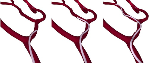
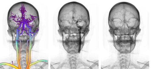
Figure 4. Left: Color-coded vascular model obtained from patient data; warmer colors correspond to increased blood flow. Center: Contrast agent injection using particle-based rendering. Right: Real-time catheter navigation and fluoroscopic rendering.
Two other important aspects that relate to visual feedback are X-ray simulation and contrast agent propagation. Both are used during interventional procedures to visualize blood vessels, as well as the anatomy. Contrast agent propagation is simulated using an advection equation where the concentration of contrast agent C(x, t) is a function of the injection rate r(t) and the averaged laminar flow velocity u(x, t).
We numerically solve (23) using a finite difference scheme. The resulting angiogram is visualized using 3D particles whose intensity values are a function of C(x, t). Similarly, we have developed a new volume-rendering approach that can render CT datasets as fluoroscopic or X-ray images in real time. The X-ray attenuation process simulates X-ray beam attenuation as described by a discretized Beer's Law Citation[14].
Algorithm 4: Substructure Gauss-Seidel algorithm
Finally, we propose a multi-modal representation of the vascular system, generated from skeletonization of patient-specific CTA datasets, as a means of ensuring consistency in the simulation. The segmentation task is particularly challenging due to the small vessel diameter and the close proximity of vessels to the skull, and thus remains semi-automatic. After applying a combination of anisotropic filtering and morphological operators, medial axis and local radius information is computed. This information is then used to automatically generate a graph of the vascular network for fluid flow computation, a set of 3D particles for contrast agent rendering, a discretization of the centerlines for contrast agent numerical computation, and a C1-continuous triangulation of the surface of the vasculature optimized for fast collision detection. An example of segmented vascular network is presented in .
Conclusions and future work
In this paper we have proposed a series of new approaches for fast and accurate simulation of catheter or guidewire navigation within a vascular network. The model we introduce for simulating wire-like structures is able to represent the complex behavior of medical devices and handles collision responses in an effective manner. We also presented results related to the development of a full simulator for interventional neuroradiology. The system runs in real time on a single-processor machine and is capable of simulating realistically key aspects of a diagnostic procedure. Current results for a 100-node model show a computation time of 25 ms for one time step (including the computation of [K], substructure analysis, collision detection, and contact response) on a Pentium 4 2.6 GHz processor. Going forward, we will address the issue of simulating devices such as stents and coils, and develop a set of metrics for measuring performance during training.
Acknowledgments
This work was supported by the Department of Defense and CIMIT (grant numbers 17-02-2-0006 and 21-45-22). We thank Drs. Vincent Luboz, Xunlei Wu, Karl Krissian and James Rabinov for their valuable help on anatomical segmentation.
Related Research Data
References
- American Heart Association. Heart and stroke facts statistics: Statistical supplement. American Heart Association, Dallas, Texas 1999
- Cotin S., Dawson S., Meglan D., Shaffer D., Ferrell M., Sherman P. ICTS, an interventional cardiology training system. Proceedings of Medicine Meets Virtual Reality 2000., JD Westwood, et al. IOS Press, Amsterdam 2000; 59–65
- Nowinski WL., Chui CK. Simulation of interventional neuroradiology procedures. Proceedings of International Workshop on Medical Imaging and Augmented Reality (MIAR’01). June. Hong Kong 2001; 87–94
- Hoefer U., Langen T., Nziki J., Zeitler F., Hesser J., Mueller U., Voelker W., Maenner R. Cathi – catheter instruction system. Proceedings of the 16th International Congress and Exhibition (CARS 2002). 2002, HU Lemke, MW Vannier, K Inamura, AG Farman, K Doi, JHC Reiber. Springer, Berlin, June, 101–106, Computer Assisted Radiology and Surgery
- Alderliesten T. Simulation of minimally-invasive vascular interventions for training purposes. Utrecht University. December, 2004, PhD dissertation
- Featherstone R. The calculation of robot dynamics using articulated-body inertias. Int J Robotics Res 1983; 2(1)13–30
- Lenoir J., Meseure P., Grisoni L., Chaillou C. Surgical thread simulation. In: MS4CMS 2002 (Modelling & Simulation for Computer Aided Medicine and Surgery 2002). European Series in Applied and Industrial Mathematics (ESAIM) Proceedings. 2002; 12: 102–107
- Przemieniecki JS. Theory of Matrix Structural Analysis. McGraw-Hill, New York 1968
- Felippa CA. A systematic approach to the element independent corotational dynamics of finite elements. Center for Aerospace Structures. 2000, Technical Report CU-CAS-00-03
- Nesme M., Payan Y., Faure F. Efficient, physically plausible finite elements. J Dingliana, F Ganovelli. Eurographics (short papers). August, 2005
- Bro-Nielsen M., Cotin S. Real-time volumetric deformable models for surgery simulation using finite elements and condensation. Computer Graphics Forum 1996; 15: 57–66
- Duriez C., Andriot C., Kheddar A. Signorini's contact model for deformable objects in haptic simulations. Proceedings of IEEE/RSJ International Conference on Intelligent Robots and Systems (IROS 2004). Sendai 2004; 3232–3237, 28 September-2 October
- Jourdan F., Alart P., Jean M. A Gauss-Seidel like algorithm to solve frictional contact problems. Comp Meth Appl Mech Eng 1998; 155: 33–47
- Wu X., Pegoraro V., Lubos V., Neumann P., Bardsley R., Dawson S., Cotin S. New approaches to computer-based interventional neuroradiology training. Proceedings of Medicine Meets Virtual Reality (MMVR) 2005., JD Westwood, et al. IOS Press, Amsterdam 2005; 602–607