Abstract
Acetabular orientation is a crucial part of the planning and performance of hip arthroplasty. Currently, most surgeons use the anterior pelvic plane (APP) to orient themselves when navigating the acetabulum, despite the fact that the anterior superior iliac spine (ASIS) of the unaffected side is not accessible in the lateral position. We have identified another plane, the transverse pelvic plane (TPP), relying on both posterior superior iliac spines and the ASIS of the affected side. In a CT-based study, this plane was found to be as reliable as the APP for the orientation of the cup in both anteversion and inclination. The substantial variation in both measurements between patients is documented, and their relation to the “safe zone” is shown. We recommend consideration of the TPP by surgeons who perform arthroplasty in the lateral position. It may reduce operating time and improve accuracy in computer-assisted arthroplasty.
Introduction
Dislocation and impingement remain significant complications in total hip arthroplasty. Revision for recurrent dislocation or early loosening secondary to impingement is associated with patient morbidity and increased healthcare costs. Several factors have been implicated in dislocation, including soft tissue laxity, bone or soft tissue impingement, and implant design parameters. However, component malpositioning, especially that of the acetabular cup, remains responsible for the majority of dislocations. It is also the most easily correctable of all the factors involved Citation[1], Citation[2].
In addition to dislocation and impingement, incorrect acetabular component positioning predisposes to accelerated component wear, pelvic osteolysis and acetabular migration Citation[3], Citation[4].
Given the need for optimal acetabular cup placement, researchers have developed image-based methods that rely on the concept of the anterior pelvic plane (APP). First described by Cunningham in 1922, the APP is based on the two anterior superior iliac spines (ASIS) and the two pubic tubercles Citation[5]. Jaramaz et al. have introduced the APP concept to computer-assisted cup placement in hip arthroplasty, and it has proved to be a useful tool Citation[6–8].
The vast majority of surgeons perform hip arthroplasty with the patient in the lateral position, using local and regional anatomical landmarks to orient the acetabulum. Most authors cite the “safe zone” of Lewinnek in relation to the APP as their target zone, that being an anteversion between 5° and 25° and an inclination between 30° and 50° Citation[9]. In the lateral position, access to the opposite ASIS can be difficult, especially in obese patients. This in turn jeopardizes the reliability of the APP as a reference system. Moreover, there is no data in the literature documenting the variability of the relationship between the APP and the acetabulum between individual patients.
In this paper we introduce the concept of the transverse pelvic plane, which is based on the two posterior superior iliac spines and one of the anterior superior iliac spines. We then use it as the basis of a reference frame for measuring acetabular inclination and anteversion.
Materials and methods
Pelvic CT scans for 24 patients were available for study. Of these patients, 14 had undergone surgery to one hip; therefore, 34 native hips were studied. A custom software program, written by one of the authors (RR), was used for 3D modeling and landmark acquisition.
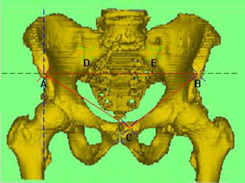
On each scan, the two anterior superior iliac spines (points A and B), the more anterior pubic tubercle (point C), and the posterior superior iliac spines (points D and E) were assigned (). The plane derived from points A, B and C is a coronal plane corresponding to the APP (APPCor). A plane through line AB and orthogonal to plane ABC is drawn to give an axial plane (APPAx). These two planes, together with a sagittal plane (APPSag) which is orthogonal to both at point A, form the APP coordinate system with its center being point A.
Figure 1. Anteroposterior view showing the anterior pelvic plane (plane ABC or APPCor, shown in green); planes APPSag and APPAx are represented by the blue and green dashed lines respectively.
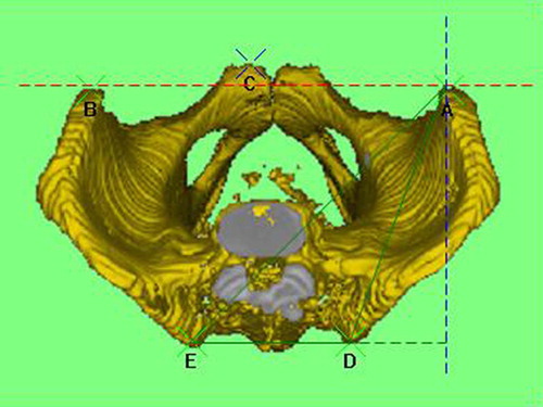
The plane derived from points A, D and E is another axial plane, which we have called the Transverse Pelvic Plane (TPPAx). The plane orthogonal to plane TPPAx and to line DE gives the sagittal plane TPPSag (). A coronal plane (TPPCor) drawn at point A parallel to line DE is perpendicular to both TPPAx and TPPSag. These three planes define the TPP coordinate system with the center at point A.
Figure 2. Cephalocaudal view showing the transverse pelvic plane (ADE or TPPAx, shown in green); planes TPPSag and TPPCor are represented by the blue and red dashed lines respectively.
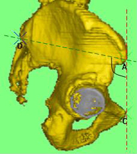
For all 34 hips, the APP, the TPP and the relationships between them were measured ().
Figure 3. Right lateral view showing the angle between planes TPPAx (green) and APPCor (red); points A and D are overlapping with points B and E, respectively.
Points were then assigned to the acetabular rim, and a plane was fitted through these points to define the acetabular plane. The angle this plane makes with the axial planes APPAx and TPPAx defines the inclination of the acetabulum, IncAPP and IncTPP, respectively. The angle the acetabular plane makes with the sagittal planes APPSag and TPPSag defines the anteversion of the acetabulum, AVAPP and AVTPP, respectively ( and ).
Figure 4. Cephalocaudal view showing the relationship between the plane of the acetabulum and plane APPAX; line FG is formed by the intersection of the two planes, and the angle between this line and plane APPSag (blue dashed line) is the anteversion relative to the APP coordinate system (AVAPP). [Color version available online.]
![Figure 4. Cephalocaudal view showing the relationship between the plane of the acetabulum and plane APPAX; line FG is formed by the intersection of the two planes, and the angle between this line and plane APPSag (blue dashed line) is the anteversion relative to the APP coordinate system (AVAPP). [Color version available online.]](/cms/asset/d7e17038-d931-4b23-9a60-5fe34ba6b37f/icsu_a_209014_f0004_b.jpg)
Figure 5. Cephalocaudal view showing the relationship between the plane of the acetabulum and plane TPPAx; line HI is formed by the intersection of the two planes, and the angle between this line and plane TPPSag is the anteversion relative to the TPP coordinate system (AVTPP). [Color version available online.]
![Figure 5. Cephalocaudal view showing the relationship between the plane of the acetabulum and plane TPPAx; line HI is formed by the intersection of the two planes, and the angle between this line and plane TPPSag is the anteversion relative to the TPP coordinate system (AVTPP). [Color version available online.]](/cms/asset/047f7a34-63ba-4f7a-8dc4-5a0e179518e1/icsu_a_209014_f0005_b.jpg)
Two independent observers were then asked to repeat the observations, from point gathering to angle measurement. Three sets of data were thereby obtained.
Results
The plane of the acetabulum can be referenced off the APP coordinate system. The average inclination IncAPP was 55°, and the range in this small series was 23° (between 43° and 66°) with a standard deviation of 5°. The anteversion in the APP AVAPP is also a reliable parameter. In this series the mean was 22°, with a range of 37° (between 7° and 44°) and a standard deviation of 7°.
The TPP (TPPAx) is reliably related to the APP (APPCor), being almost perpendicular at 104°, with a range of 29° (from 91° to 120°) and a standard deviation of 7°. Relative to the TPP coordinate system, the average acetabular inclination IncTPP was 60°, with a range of 23° (between 48° and 71°) and a standard deviation of 5°. The average anteversion AVTPP was 30°, with a range of 31° (between 15° and 46°) and a standard deviation of 6°.
lists the anteversion and inclination data obtained by each independent observer for all 34 hips studied. We looked at the variation between observers, and found that both frames of reference were reliable, showing similar characteristics. The reliability correlations are shown in , revealing that the TPP is a frame of reference that is as reliable as the APP for the purposes of defining the position of the acetabulum.
Table I. Acetabular anteversion (AV) and inclination (Inc) in relation to the APP and TPP coordinate systems.
Table II. Reliability correlations for the APP and TPP coordinate systems. (AV = anteversion; Inc = inclination)
shows the anteversion and inclination angles relative to the APP coordinate system in relation to the safe zone of Lewinnek Citation[9]. It can be seen that there is substantial scatter between subjects. Moreover, out of the 34 hips studied, only six (18%) fell within the so-called “safe zone”.
Figure 6. Scatter diagram showing the average anteversion (AVAPP) and inclination (IncAPP) angles for the 34 hips relative to the APP. The “safe zone” of Lewinnek is also shown (dashed lines). [Color version available online.]
![Figure 6. Scatter diagram showing the average anteversion (AVAPP) and inclination (IncAPP) angles for the 34 hips relative to the APP. The “safe zone” of Lewinnek is also shown (dashed lines). [Color version available online.]](/cms/asset/f930dec9-c5ba-4fe7-89df-992fc2c3dd21/icsu_a_209014_f0006_b.jpg)
Discussion
The anterior pelvic plane is a popular reference frame for acetabular orientation in 3D space. It has been the cornerstone of image-based hip navigation technologies. However, an important practical limitation of the APP is the inaccessibility of the opposite ASIS when the patient is in the lateral position. This can have serious consequences as the orientation accuracy can be jeopardized. To overcome this problem, some centers recommend acquiring the APP coordinate system landmarks in the supine position prior to turning the patient to the side, thereby increasing the operating time considerably.
We have observed that, while the patient is in the lateral position, both posterior superior iliac spines are readily palpable bony landmarks. This has led us to the concept of the transverse pelvic plane. The acetabular data obtained here show that the TPP, like the APP, may be used as a reliable reference frame. The data also demonstrate that the inter-observer variability is not statistically significant, making the TPP a reliable and reproducible frame of reference. Moreover, with its more easily identifiable landmarks with the patient in the lateral position, this new reference frame has significant attraction for surgeons who use CT-free planning and navigation.
This CT-based study also highlights the variation in the acetabular anteversion and inclination between individuals. We have found that the variation is substantial, and is as great in relation to the APP coordinates as it is in relation to the TPP coordinates ().
As can be seen in , only 18% of the 34 hips studied had anteversion and inclination values that were within the so-called “safe zone”. This reflects the fact that there is a profound difference between the anatomies of individual patients. Optimal placement of acetabular components should be influenced by this information. Preoperative planning using the patient's own dataset rather than set “normal” parameters should allow the surgeon to make a plan that is more reliable, and hence safer, avoiding the risk of impingement and dislocation.
The TPP is therefore a reliable practical frame of reference that can be used by surgeons when navigating the acetabular component. Its adoption may save time and effort, improving outcomes in computer-assisted arthroplasty.
References
- Daly PJ, Moorey BF. Operative correction of an unstable total hip arthroplasty. J Bone Joint Surg Am 1992; 74: 1334–1343
- Hedlundh U., Sanzen L., Fredin H. The prognosis and treatment of dislocated total hip arthroplasties with a 22 mm head. J Bone Joint Surg Br 1997; 79: 374–378
- Bernsmann K., Langlotz U., Ansari B., Wiese M. Computer-assisted navigated acetabulum placement in hip prosthesis implantation – application study in routine clinical care. Z Orthop 2000; 138: 515–521
- Coventry MB., Beckenbaugh RD., Nolan DR., Ilstrup DM. 2,012 total hip arthroplasties. J Bone Joint Surg Am 1974; 56: 273–284, A study of postoperative course and early complications
- Cunningham DJ. Pelvis. Cunningham's Textbook of Anatomy, DJ. Cunningham. Hodder & Stoughton, London 1922; 255–260
- Jaramaz B., DiGioia AM., Blackwell M., Nikou C. Computer assisted measurement of cup placement in total hip replacement. Clin Orthop Rel Res 1998; 354: 70–81
- DiGioia AM., Jaramaz B., Blackwell M., Simon DA., Morgan F., Moody JE., Nikou C., Colgan BD., Aston CA., LaBarca RS., Kischell E., Kanade T. The Otto Aufranc Award. Image guided navigation system to measure intraoperatively acetabular implant alignment. Clin Orthop Rel Res 1998; 355: 8–22
- Zheng G., Marx A., Langlotz U., Widmer KH., Buttaro M., Nolte LP. A hybrid CT-free navigation system for total hip arthroplasty. Comput Aided Surg 2002; 7: 129–145
- Lewinnek GE., Lewis JL., Tarr R., Compere CL., Zimmerman JR. Dislocations after total hip-replacement arthroplasties. J Bone Joint Surg Am 1978; 60: 217–220