Abstract
After several years of product development, animal trials and human cadaver testing, the SpineAssist®–a miniature bone-mounted robotic system–has recently entered clinical use. To the best of the authors’ knowledge, this is the only available image-based mechanical guidance system that enables pedicle screw insertion with an overall accuracy in the range of 1 mm in both open and minimally invasive procedures.
In this paper, we describe the development and clinical trial process that has brought the SpineAssist to its current state, with an emphasis on the various difficulties encountered along the way and the corresponding solutions. All aspects of product development are discussed, including mechanical design, CT-to-fluoroscopy image registration, and surgical techniques. Finally, we describe a series of preclinical trials with human cadavers, as well as clinical use, which verify the system's accuracy and efficacy.
Introduction
The initial versions of Computer Assisted Surgery (CAS) and Robotics Assisted Surgery (RAS) were introduced into the operating room (OR) in the 1990s (see reference Citation[1] for a comprehensive overview of medical robotics, and also references Citation[2–4]). Various pioneer systems in both fields were developed, tested and used in the clinic during this decade. The prominent players in the CAS arena were the navigation system developers such as Medtronic (Sofamor Danek), Aesculap, BrainLAB and GE, while the most notable RAS developers were Computer Motion (Aesop), ISS (Robodoc) and Intuitive Surgical (DaVinci).
Today, navigation systems are primarily used in the OR for neurosurgery, with approximately 2,000 neurosurgery units in use. Navigation system usage in other disciplines has been limited by several factors, such as a lack of proof of their added clinical value; the need for an unobstructed line of sight in optical-based navigation or non-ferromagnetic tools in the magnetic version; and the high cost of these systems.
Surgical robots offer a distinct added value and may pave the way for new procedures that are not feasible with current CAS systems, particularly when greater accuracy is required than can be achieved by the surgeon using a freehand technique and in minimally invasive procedures. However, surgical robots are by their nature more complicated systems, and have exhibited a slower adoption rate in the clinic, mainly as a result of difficulties regarding the surgical technique, the large or cumbersome size of the devices, and the need to immobilize the patient when using active or semi-active robots.
The SmartAssist® (Mazor Surgical Technologies, Caesarea, Israel) was designed to overcome the above limitations by using a miniature robot that is directly mounted on the patient's bony anatomy and moves in unison with the body.
Clinically tested for use in spinal fusion, the SpineAssist® (the spinal application of the SmartAssist®) is attached to a vertebra, rendering the spine and the robot a unified rigid body. This approach ensures that patient breathing and movement do not change the position of the robot relative to the vertebra, thus providing for significantly higher accuracy in the insertion of implants such as pedicle screws.
To facilitate acceptance, a semi-active robotic system was designed to accurately guide and assist the surgeon in placing spinal implants, as opposed to a fully automatic system that performs the surgical operation autonomously. The actual surgical procedure employing the SpineAssist, e.g., drilling, is performed by the surgeon, not by the robot, and the surgeon remains in full control at all times.
The purpose of this paper is to describe the system's evolution from concept to clinical use. Special attention is given to the unexpected difficulties encountered and the ways in which we overcome them, encompassing various aspects of this surgical robotic system such as its kinematic structure, image registration, bone-mounting issues, and surgical techniques.
System description and the surgical procedure
In spinal fusion, pedicle screws are often used for stabilization. A metal screw is inserted into each of the pedicles of the vertebrae involved in the operation–two screws per vertebra–and a rod is inserted through the heads of all the screws on each side to support the spinal column internally.
Accurate positioning of pedicle screws is highly desirable given the proximity of the spinal cord to its branching nerve roots, as well as to major blood vessels such as the aorta and vena cava. Accurate positioning is also desired to ensure the highest probability of proper stabilization until bone fusion is achieved.
The present investigation describes the insertion of pedicle screws with high accuracy in a minimally invasive manner using a robotic positioning system.
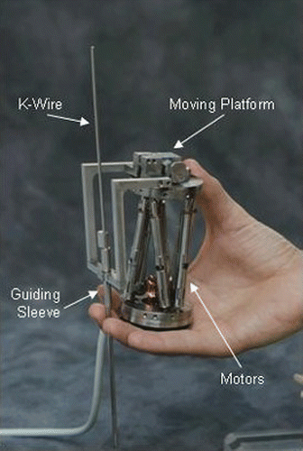
The system consists of two units: a miniature parallel robot () that can move its end-effector with six degrees of freedom; and a workstation that runs a graphic user interface software and performs the preoperative planning, image acquisition and registration, kinematic calculations, and real-time control of the robot motion.
During surgery, the robot base platform is mounted on the vertebra using a specially designed, disposable clamping system. The coordinates of the desired screw insertion axis are obtained from a preoperative plan made by the surgeon on reconstructed CT images. These coordinates are translated to the desired motion of each of the robot's six actuators, and the system controls the movement of the robot to the desired position following an automatic CT-to-fluoroscopy registration process. The surgeon then inserts guide wires or operates surgical tools through a cannulated guide attached to the robot's moving top platform.
The surgical procedure consists of the following steps:
Preoperative planning. The surgeon chooses the implants to be used and plans the desired entry point and trajectory for each vertebra. This is performed using three projections of each vertebra–anterior-posterior, lateral and axial–which are reconstructed from a preoperative CT scan ().
Attachment to bony anatomy. A specially designed clamp is rigidly attached to the vertebrae in proximity to the site of operation (). Alternatively, a minimally invasive Hover-T frame is attached to the iliac crest and a vertebra ().
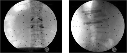
Image acquisition and registration. A geometric relation between the coordinate systems of the clamping assembly, the patient's anatomy, and the preoperative plan is established automatically by matching the preoperative reconstructed CT images to intraoperative fluoroscopic images of the patient with the clamping assembly and targeting device in place (). This CT-to-fluoroscopy image registration is performed automatically, and the surgeon verifies and approves the result.
Robot assembly and motion. The targeting devices are replaced by a multi-level bridge onto which the robot is mounted. This bridge enables the operation of several vertebrae without changing the clamp position, and can be further stabilized by inserting two pins through its edges into adjacent levels of the spine. When using the Hover-T, there is no need for the bridge and the robot is assembled directly on the Hover-T frame. The controller moves and then locks the robot into position so that the cannulated guide is aligned with the planned trajectory. The cannulated guide is locked into the targeted anatomy via taps that anchor endpoint pins into the bone.
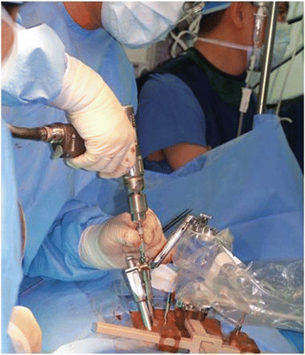
Manual execution. The surgeon now executes drilling, resection, or introduction of a needle or guide-wire through the cannulated guide (). Robot motion and manual execution are repeated for all planned implants consecutively.
Figure 2. Planning a screw insertion in three orthogonal projections. [Color version available online.]
![Figure 2. Planning a screw insertion in three orthogonal projections. [Color version available online.]](/cms/asset/be591058-d4ae-4bc0-b364-05bfa6cd0a15/icsu_a_224311_f0002_b.gif)
Development process
Several years of development and tests were required to obtain a clinically validated system. This effort included simulations, several prototypes, animal and cadaveric experiments, and tool development, as well as development of the surgical procedure itself. This section details the development process, problems encountered, and the solutions adopted, as we consider it important to share the accumulated experience with developers of future RAS systems.
Robot structure
Starting with computer simulations, the procedure of pedicle screw insertion was thoroughly examined from the workspace, force, and accuracy points of view. It should be noted that, especially with small work volume parallel robot designs, these criteria define the robot dimensions and therefore have a major effect on the feasibility of a bone-attached system. The physical strength and 3D geometry of lumbar vertebrae were evaluated and tests were conducted, first on single-vertebra specimens Citation[5] and later with a full lumbar dry bone specimen. The goal was to enable the robot to reach all possible placement directions for spinal implants without interference. Different clamp positions and variations between patients or between vertebrae levels of the same patient were also taken into account. These studies set the limits on the weight of the robot and also defined the requirements for its size and work volume.
These investigations were followed by an analysis of the forces applied to the robot during the surgical procedure, which yielded strength requirements for the robot of 10 kg in all directions and an actuation force in excess of 1 kg. The robot accuracy is 0.1 mm with a resolution of 20 microns.
The workspace analysis yielded the particular robot structure, but it was found that more than one arm was necessary to cover the workspace efficiently while remaining within the size and weight limits appropriate for a bone-attached robot system. As the human cadaver trials progressed, we encountered degenerative cases and spinal deformities, as well as requests from clinicians that the system be made capable of supporting thoracic and translaminar procedures as well. New arm designs were therefore developed to accommodate these new work volume requirements.
After dozens of structure simulations, several prototypes, and approximately 18 months of intensive research and development efforts, the final design is a six-degree-of-freedom robot, featuring a cylindrical shape measuring 50 × 80 mm and weighing 250 g. The bottom plate of the device is affixed to the bony anatomy of the patient and its top platform is free to move on six actuators, each of which is independently controlled in a closed loop.
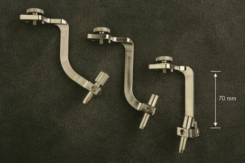
shows the three arms with different lengths and angulations for the required work volume. Using three different arms with the ability to move and lock along the clamping mechanisms extends the work volume of the robot. In practice, these arms plus lateral extensions were sufficient to cover all cases we dealt with, including placement of translaminar screws. The work volume of the combined robot and its arms is ±50 mm at the entry point with 50° angulation.
Following several focus groups with orthopaedic spine surgeons and neurosurgeons, it was decided to develop the SpineAssist as a semi-active rather than an active robotic system. That is, the robot points to the insertion point and sets the trajectory of the surgical tool, but the actual surgical operation, be it drilling, tapping, or implant insertion, is conducted by the surgeon.
At any time during the operation, the surgeon may override the system's guidance and take over the surgical procedure. It was concluded that most surgeons would prefer to maintain control over the surgical procedure and will more readily accept an assisting device than an autonomous surgical system. It was also found that the challenge which surgeons defined as the one in which they most required assistance was the determination of the orientation and location of surgical tools during the operation, especially while implementing minimally invasive approaches and when faced with deformities, revisions and complicated cases.
CT-to-fluoroscopy automatic registration
Considerable effort has been devoted to the development of an accurate and robust automatic image registration algorithm. The registration algorithm matches the pre-operative CT with the intraoperative fluoroscopic images and aligns them with the coordinate system of the clamping device. This procedure is executed for each vertebra separately after segmentation is performed. The reason for this is that each vertebra is viewed as a separate rigid body which may change its position relative to an adjacent one as a result of different preoperative and intraoperative body positions.
To minimize the use of fluoroscopy and reduce harmful radiation exposure in the OR, registration is performed with a single set of fluoroscopic images for all the vertebrae in the field of view of the fluoroscope–typically 4 vertebrae with a 12-inch fluoroscope and 2–3 vertebrae with a 9-inch machine. This also significantly reduces the complexity and length of the registration procedure. Having completed this procedure, the software can now calculate and control the motion of the robot, which is attached to the clamping device, in order to align the guiding arm with the preoperatively planned screw axis.
To ensure overall accuracy in the range of 1 mm, we require a helical CT scan with slice thickness of 1.0–1.5 mm and slice spacing of 1.0–1.5 mm. These are standard requirements typical of CAS CT protocols for existing navigation systems.
A necessary step toward achieving accurate image registration is C-arm calibration. This is essential to overcome distortions in the fluoroscopic images and is executed in the OR prior to every operation. Calibration is achieved by using a phantom with a known pattern of radio-opaque spheres and acquiring a blank vertical (AP) image and a blank horizontal (LT) image. A de-warping calculation is then performed that enables the system to compensate for distortions generated by surrounding magnetic fields, such as that of the Earth and those generated by electronic equipment in close proximity to the surgical field (for more on de-warping algorithms, see reference Citation[6]).
For connecting to the C-arm, we use the machine's video output BNC connector. This connection does not give the best possible image quality and resolution, but is the most convenient way to acquire video output from the C-arm. As we wanted the system to be easy to use without the need for dedicated personnel, the image registration algorithm was designed to cope with the reduced-quality image for the benefit of simplicity in connecting to existing OR equipment.
Throughout the development process it was discovered that the algorithm would have to cope with great variations in image quality. Any number of spheres can be hidden by the bony anatomy of the patient. On moving from dry bone specimens to human cadaveric experiments, we discovered that the thickness and type of soft tissue surrounding the bones leads to significant variations in exposure levels and greatly affects the ability to recognize the spheres. On progressing to clinical cases, we encountered obese patients who further complicated this issue.
During the development process, 12-inch C-arms were used. However, it was found that in many hospitals 9-inch machines are the standard. Though no major change in the algorithm was required, a different calibration phantom had to be developed that matched the smaller diameter intensifier. Moreover, due to the smaller field of view, special attention should be paid to the fluoroscopic image acquisition in the OR to ensure that the targeting devices are fully included within the field of view along with a maximal number of vertebrae.
Clamping mechanism
To achieve the high accuracy required for insertion of pedicle screws or any other spine-related procedure, it is necessary that the robot be affixed to the vertebra and move with it as a single rigid body. The clamping mechanism that connects the robot to the spine must therefore provide such rigidity.
Preliminary experiments were conducted on animal models to evaluate various clamping concepts, bone strength, and their effect on the accuracy of the line of insertion. The initial concept was to attach the robot to the spinous process using K-wires. In an experiment conducted on a sheep cadaver, multiple K-wires were inserted into the spinous process and attached to a guiding sleeve through which a surgeon drilled into the pedicle of the same vertebra. The forces and moments applied by the surgeon during drilling were measured by a force/moment sensor and the results reported in reference Citation[7]. Deviations due to the applied force where also verified in several other experiments and reported in reference Citation[8]. Results obtained from animal trials showing the feasibility of the system were reported in references Citation[9] and Citation[10].
To enable fast and easy shifting of the robot from one vertebra to the next, the spinous process clamp was developed to replace the K-wires as a means of attaching the robot to the spine.
Following requests from surgeons wishing to operate on multiple vertebrae via a single, small incision and using a single set of fluoroscopic images, a multi-level bridge was developed and tested (). The bridge has three stations to which the robot can be attached–center, head and feet–and it enables operation on at least three vertebrae without the need to move the clamp. This raised the question of inter-segmental movements in the spine–to what degree could adjacent vertebrae move relative to one another and how would this affect the accuracy of the insertion point and axis?
Experiments with animal models and human cadavers were conducted and showed that the relative motion is minimal (in the range of 0.2 mm) for forces of 20 N, and is further reduced in degenerative spines. It should be mentioned that the deviations are measured in the lateral position, since motion of the vertebra along the insertion direction, i.e., along the line of force application, does not cause deviation of the screw axis line. Inter-segmental movement is still further reduced once the bridge is stabilized with threaded K-wires inserted into the spinous process of the adjacent levels on each side of the clamp (see ).
The use of the multi-level bridge to operate on several vertebrae reduces the amount of X-ray radiation exposure in the OR and shortens the length of the procedure. It also facilitates revision surgeries on vertebrae that have previously had their spinous processes removed by attaching the clamp to an adjacent level. Even so, the multi-level bridge was sometimes found to be too long for comfortable use, especially at the lower lumbar and upper sacral levels (L4-L5-S1) or when a single-level operation was planned that involved only two adjacent vertebrae. A single-level bridge was developed for this purpose, which is stabilized with a single threaded K-wire to the adjacent vertebra.
Finally, to facilitate minimally invasive procedures, a T-shaped frame (Hover-T©, Mazor Surgical Technologies, Caesarea, Israel) was developed and used clinically (). The Hover-T is attached to the iliac crest with two pins and to the spinous process of a single vertebra with a single threaded K-wire. The robot is attached to a carriage that can slide along the long bar of the frame, floating above the spine and covering the entire lumbar spine, including the lower thoracic levels and upper sacrum. This setup also facilitates another surgical procedure that requires an extreme lateral approach to the spine–spinal fixation using translaminar facet screws.
Surgical accessories
The results of the accuracy test referred to in the preceding section were obtained under extreme conditions in which no support was given to the cannulated guide at the bone entry point. To achieve better accuracy, the cannulated guide sleeve was equipped with sharp teeth at the tip that bite into the cortex, locking the sleeve at the entry point and stabilizing its trajectory.
On progressing to clinical cases, the need arose for accessories that would enable a percutaneous approach, in which the surgical tools are introduced through a small incision in the skin. This required tools that could create a path through soft tissues, mainly muscle, all the way to the bone. A blunt insert was developed that is screwed into the long guide tube. Together they are introduced through the skin incision and create the path to the bone by splitting muscles and other soft tissues without actually cutting through them. The guide tube is then locked in place, the blunt insert is removed, and the cannulated guide is inserted and tapped into the bone.
Accuracy verification process
The process of evaluating and verifying the overall accuracy of the system included two distinct stages:
1 - Early stage trials
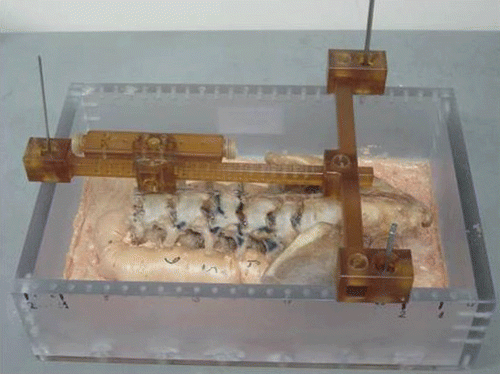
Early stage trials were conducted using a dry bone specimen that was attached to a fixed jig equipped with radio-opaque metal spheres at known locations (). This apparatus provided an efficient tool for checking the accuracy of all components of the system, including the registration error propagation, clamping device, robot structure, controller and arm design. The specimen underwent pre-intervention CT scanning, which was followed by the registration process to match the CT images to the fluoroscopic images.
Using this apparatus, it was possible to compare pre- and post-intervention CT scans and to measure overall system accuracy, since the locations of the screws were planned on the CT images along previously drilled holes filled with a radio-opaque substance that could be observed on the pre-operative images. Results of the complete process conducted on this jig were reported in reference Citation[8].
2 - Preclinical trials
The second stage of accuracy verification included extensive preclinical trials with human cadavers, conducted from February to April 2005. Ten human cadavers were used and 54 implants were inserted Citation[11–13]. These trials included all possible scenarios of open surgery, open surgery with screw insertion via percutaneous approaches using the spinous process clamping apparatus, and minimally invasive surgery using the Hover-T.
Pedicle screws and K-wires were inserted, as well as translaminar facet screws and K-wires. The implants were left inside the cadavers and post-procedural CT scans were employed to analyze the overall system accuracy. Accuracy was calculated using the same registration process for pre- and postoperative CTs. DRR (Digital Reconstructed Radiograph) was used to create AP, lateral and axial projections from the postoperative CT, and automatic registration was performed to match these projections to the preoperative reconstructed CT projections.
Accuracy was calculated as the deviation of the actual position of a screw/K-wire from the preoperative plan (some examples are given in ). Typical post-procedural CT reconstructions of accurate placements are shown in . The results of these trials were as follows:
Figure 8. Actual versus planned drill positions for pedicle screw (a) and translaminar screw (b). [Color version available online.]
![Figure 8. Actual versus planned drill positions for pedicle screw (a) and translaminar screw (b). [Color version available online.]](/cms/asset/4c98e9ea-f849-40ca-8581-989c4859cfa9/icsu_a_224311_f0008_b.gif)
Table I. Accuracy analysis.
Thirty-five pedicle implants were inserted with the following results:
Overall average deviation: 0.97 ± 0.61 mm (0–1.7 mm)
Average deviation in particular planes:
AP: 1.09 ± 0.56 mm (0–1.5)
Lateral: 0.76 ± 0.57 mm (0–1.5)
Axial: 1.05 ± 0.65 mm (0–1.7)
Nineteen translaminar facet screws were inserted with the following results:
Overall average deviation: 0.85 ± 0.67 mm (0–1.5 mm)
Average deviations in particular planes:
AP: 1.30 ± 0.27 mm (0–1.5)
Lateral: 0.30 ± 0.67 mm (0–1.5)
Axial: 0.95 ± 0.62 mm (0–1.5)
After eliminating the outliers, i.e., the wires that were broken, bent, pulled out, etc., the analysis of this study gives 47 accurate placements–“accurate” meaning a deviation of less than 1.5 mm from the planned trajectory–and one misplaced K-wire, yielding 97.9% success (47/48).
In addition to measuring system accuracy, these trials were used to evaluate and improve the surgical technique and the tip design of the cannulated guide. The combination of the latest tip design for the cannulated guide, stiffening the arms, and the improved surgical technique reduced skidding significantly and yielded more accurate results, as can be seen by comparing the mean error for the last 20 placements–performed using the latest technique and the newest tip - with the mean error for the previous 34 placements in this series of experiments. It was not possible to measure separately the contribution of each improvement, but the combined results were as follows:
Average LT error was reduced from 0.68 mm to 0.42 mm–a 38% improvement.
Average AP error was reduced from 1.13 mm to 0.78 mm–a 31% improvement.
Average axial error was reduced from 1.04 mm to 0.94 mm–a 10% improvement.
Clinical use data
Between April and October 2006 the SpineAssist was used in 65 clinical cases in the United States, Germany and Israel. Patient conditions included several types of spinal deformities, as well as revision surgeries, and procedures included surgery on the sacral, lumbar and thoracic spine.
The advantages of the SpineAssist were demonstrated particularly in the more complex cases. Minimally invasive surgeries (MIS) were carried out using the Viper™ (Depuy) and Atavi® (Endius) systems, facilitating a truly minimally invasive approach. In revision cases the system proved useful in facilitating accurate placements where the lack of anatomical landmarks made it very difficult for the surgeons to otherwise locate the entry point and trajectory. Lastly, in deformity cases, the system proved valuable in providing accurate guidance even in the presence of severe deformities.
Forty-six of these cases were executed using the bridge and clamp mechanism, and the remaining 19 cases used the Hover-T. Most of the cases (53%) used a percutaneous approach, 36% used the more traditional open approach, and 11% involved a combined percutaneous/open approach.
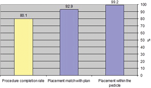
A total of 316 screws were planned and 253 (80.1%) were actually inserted using the SpineAssist system. In 19 cases, at least one of the 4–6 planned screws was not executed for some reason (a clinical consideration or technological limitation); these cases were counted in the study as non-completed cases. Reasons for not fully completing all the planned screws included unmatched fluoroscopy-to-CT images (6 cases: 9%), technological problems (6 cases: 9%), clinical difficulty (3 cases: 4.6%), and the planned trajectory being outside the working volume of the robotic device (4 cases: 6%).
Of the 253 implanted screws, 235 (92.9%) were accurately placed according to the plan. The remainder–with two exceptions–were placed within the pedicle, which means they would provide clinically acceptable results. In only two cases (0.8%) did the system point outside the pedicles: this was detected by intraoperative X-rays and the screws were inserted manually instead of in accordance with the system's guidance. The results are summarized in . As the SpineAssist is a newly introduced device, most of the results were obtained during the surgeons' learning phase; performance is expected to improve with experience.
It is important to note that postoperative CT scans were obtained for several of the patients, and hence the results are based partly on pre- to postoperative CT and partly on postoperative fluoroscopy images ().
Conclusions
This study shows that robotically assisted implant insertion in spinal surgery is feasible and enhances placement accuracy, especially in complicated cases. One of the most attractive features of this technology is its ability to facilitate minimally invasive procedures, as was demonstrated by completing the procedure for rod insertion and dynamic stabilization using several commercially available systems. Other compelling indications are deformity and revision cases, where the surgeon's ability to find the correct entry point and trajectory is diminished by unusual or absent anatomical landmarks.
Procedure completion rates are approximately 80%. Accurate placement is achieved in close to 93% of cases, with clinically acceptable placement within the pedicle being achieved in 99% of cases. These results verify the system's accuracy and support its use in minimally invasive and open spine surgery for pedicle screws, as well as for translaminar facet screw techniques.
References
- Taylor RH, Stoianovici D. Medical robotics in computer-integrated surgery. IEEE Trans Robotics Automation 2003; 19(5)765–781
- DiGioia A, Jaramaz B, Colgan B. Computer assisted orthopaedic surgery: Image guided and robotic assistive technologies. Clin Orthop Rel Res 1998; 354: 8–16
- Simon DA, Lavallée S. Medical imaging and registration in computer assisted surgery. Clin Orthop Rel Res 1998; 354: 17–27
- Nolte LP, Slomczykowski MA, Berlemann U, Strauss MJ, Hofstetter R, Schlenzka D, Laine T, Lund T. A new approach to computer-aided spine surgery: Fluoroscopy-based surgical navigation. Eur Spine J 2000; 9 Suppl 1: 78–88
- Wolf A, Shoham M, Schnider M, Roffman M. Morphometric study of the human lumbar spine for operation-workspace specifications. Spine 2001; 26(22)2472–2477
- Livyatan H, Yaniv Z, Joskowicz L. Robust automatic C-arm calibration for fluoroscopy-based navigation: A practical approach. Proceedings of the 5th International Conference on Medical Image Computing and Computer Assisted Intervention (MICCAI 2002), Tokyo, Japan, September 2002. Part II. Lecture Notes in Computer Science 2489, T Dohi, R Kikinis. Springer, Berlin 2002; 60–68
- Wolf A, Shoham M, Schnider M, Roffman M. Feasibility study of a mini robotic system for spinal operations: Analysis and experiments. Spine 2004; 29(2)220–228
- Natanzon A, Vitchevsky A, Silberman B, Batkilin E, Burman M, Shoham M. Validation of robotically-assisted system for spinal procedures. Proceedings of the Fourth Annual Conference of the International Society for Computer Assisted Orthopaedic Surgery (CAOS-International). Chicago, IL June 2004
- Shoham M, Burman M, Zehavi E, Joskowicz L, Batkilin E, Kunicher Y. Bone-mounted miniature robot for surgical spinal procedures. Proceedings of the Second Annual Conference of the International Society for Computer Assisted Orthopaedic Surgery (CAOS-International). Santa Fe, NM June 2002
- Shoham M, Burman M, Zehavi E, Joskowicz L, Batkilin E, Kunicher Y. Bone-mounted miniature robot for surgical procedures: Concept and clinical applications. IEEE Trans Robotics Automation 2003; 19(5)893–901
- Togawa D, Lieberman IH, Benzel BC, Kayanja MM, Reinhardt MK, Zehavi E. Bone-mounted miniature robot for spinal surgery - accurate insertion for pedicle screws and translaminar facet screws in cadaveric experiments. Proceedings of the 12th International Meeting on Advanced Spine Techniques (IMAST), Banff, Alberta, Canada. July 2005
- Lieberman IH, Togawa D, Benzel EC, Kayanja MM, Reinhardt MK, Friedlander A, Knoller N. Bone-mounted miniature robot for pedicle screw and translaminar facet screw placement–Part I. Technical development and test case result. J Neurosurg 2006; 59(3)641–650
- Togawa D, Kayanja MM, Lieberman IH, Benzel EC, Reinhardt MK, Friedlander A, Knoller N. Bone-mounted miniature robot for pedicle screw and translaminar facet screw placement–Part II, Evaluation of system's accuracy, (Submitted)

![Figure 4. Clamp and targeting device mounted on the spinous process. [Color version available online.]](/cms/asset/e5302591-a3c9-44be-9609-883005d97c50/icsu_a_224311_f0004_b.gif)
