Abstract
Due to the difficulty of determining the 3D boundary of the cement-bone interface in Revision Total Hip Replacement (RTHR), the removal of the distal intra-femoral bone cement can be a time-consuming and risky operation. Within the framework of computer- and robot-assisted cement removal, the principles and first results of an automatic detection and 3D surface reconstruction of the cement-bone boundary using A-mode ultrasound are described. Sound propagation time and attenuation of cement were determined considering different techniques for the preparation of bone cement, such as the use of a vacuum system (Optivac®, Biomet). A laboratory setup using a rotating, standard 5-MHz transducer was developed. The prototype enables scanning of bisected cement-prepared femur samples in a 90° rotation range along their rotation axis. For system evaluation ex vivo, the distal femur of a human cadaver was prepared with bone cement and drilled (Ø 10 mm) to simulate the prosthesis cavity in a first approximation. The sample was cut in half and CT scanned (0.24 mm resolution; 0.5 mm distance; 0.5 mm thickness), and 3D voxel models of the manually segmented bone cement were reconstructed, providing the ground truth. Afterwards, 90° segments of each ex-vivo sample were scanned by the A-mode ultrasound system. To obtain better ultrasound penetration, we used coded signal excitation and pulse compression filtering. A-mode ultrasound signal detection, filtering and segmentation were accomplished fully automatically. Subsequently, 3D voxel models of each sample were calculated. Accuracy evaluation of the measured ultrasound data was performed by ICP matching of each ultrasound dataset (∼8000 points) to the corresponding CT dataset and calculation of the residual median distance error between the corresponding datasets. Prior to each ICP matching, an initial pre-registration was calculated using prominent landmarks in the corresponding datasets. This method yielded a median distance error in the region of 0.25 mm for the cement-bone interface in both femur halves.
Introduction
Total Hip Replacement (THR) is a common procedure in orthopaedic surgery. Indications for the procedure are mainly osteoarthritis, followed by fracture and inflammatory arthritis. Despite numerous advances in prosthesis design and operative techniques, aseptic loosening with or without osteolysis is still a major problem affecting the long-term outcome of THR and constitutes 75% of possible complications Citation[1], Citation[2]. The 10-year survival rate for cemented, uncemented and hybrid prosthesis designs ranges from 88 to 95% Citation[2]. As a consequence, the prosthesis often needs to be revised with a Revision Total Hip Replacement (RTHR). Although the number of uncemented prostheses continues to increase in young patients, well over 90% of prostheses are still cemented Citation[3]. Particularly for older patients, cemented implants are preferred due to the shorter immobilization time required. In RTHR on patients with cemented implants, any remaining cement has to be removed Citation[4], which can be very challenging. Conventionally, cement removal is done proximally by splitting the cement carefully with a mallet and chisels. Possible complications are partial damage to the host bone, cortical wall penetration, or femoral fracture. If removal is insufficient, the cement remaining inside the intramedullary femur could cause instability of the revised impl Citation[4], Citation[5]. The more distal the cement is located, the more difficult it is to remove. Due to the narrowness of the femoral cavity, as well as the presence of blood and particles from the removed cement, it is nearly impossible to operate under direct visual control. Therefore, fluoroscopic images are used to assist the surgeon with intra-femoral orientation of the instruments, especially in the very distal area. Depending on the complexity of the surgical case, it may be necessary to acquire as many as 50 images, resulting in high radiation exposure not only for the patient, but also for the surgeon and operating room s Citation[6], Citation[7].
Many novel approaches to cement removal have been investigated in recent years, including removing the cement by selective laser ablation Citation[8–10] or with an acoustic emission-controlled milling device Citation[11], melting the cement with high-energy ultrasound Citation[12], Citation[13], using extra- or intracorporeal lithotripsy for ablation of the cement Citation[14–17], or using pneumatic chisels under visual control by means of an endoscop Citation[18], Citation[19]. None of these approaches has led to a breakthrough. In cases where the distal cement plug cannot be removed via the femoral canal, a common practice is to cut a window in the distal cortex or even open the femur by means of extended trochanteric osteotomy Citation[20], Citation[21].
The advantages of computer-assisted navigation and robotics could overcome the aforementioned problems by a combination of navigation techniques and intelligent milling tools Citation[5]. Navigation systems could provide 3D information regarding the position of extraction tools relative to the femur and bone cement during manual removal of cement, whereas a miniaturized robotic device using 3D information about the relative position of the cement mantle could be used for automatic cement removal Citation[34]. Preoperative data acquisition by CT or MR is not feasible due to the presence of the metallic prosthesis. On the other hand, intraoperative CT or MR is usually not available and is also very expensive. A previous study of fluoroscopy-based intraoperative reconstruction of intra-femoral bone cement has been validated in reference Citation[22]. Although the demonstrated method offers a significant reduction in total X-ray dose (requiring a maximum of 6 X-ray images), the semi-automatic segmentation algorithm is not sufficiently sensitive for detection of concave-shaped cement-bone boundaries.
Intraoperative ultrasound could overcome these disadvantages. Ultrasound introduce no X-ray radiation and offers more portability in comparison to other modalities. Because of the very high ultrasound attenuation of bone Citation[23], an intra-femoral approach should be chosen. Detection of bone cement could be addressed as a thickness-measurement task, wherein the information has to be calculated by extracting the inner and outer boundaries of the bone cement mantle. Commercial ultrasonic thickness gauges usually employ the A-mode ultrasound single-element technique. Because A-mode ultrasound systems only require one channel for sending and receiving, the hardware is very compact and is also cost-efficient. The use of A-mode ultrasound for thickness determination of soft tissue in orthopaedic surgery has already been demonstrated in previous work Citation[24–26]. In this paper, we describe the principles of intra-femoral bone cement detection with A-mode ultrasound, taking into account the ultrasound-specific physical properties of the cement. A laboratory prototype has been developed to automatically scan and detect the interface between cement and bone in the distal part of an ex-vivo femur sample.
Materials and methods
For A-mode ultrasound-based intra-femoral bone cement detection a rotating scanning device is required. Whereas commercial endoscopic ultrasound (EUS) devices for gastrointestinal tract, oesophagus or intravascular investigation are mainly constrained to soft tissue investigatio Citation[27], Citation[30], the requirements for intra-femoral bone cement detection are different. As part of this study, we have investigated parameters such as the anticipated workspace and cement thickness, ultrasound-specific material properties of bone cement, and reflection coefficients of the cement-bone interface.
Ultrasound-specific properties of bone cement
The chemical composition of bone cement is mainly acrylic PMMA (polymethylmethacrylate). Intraoperative manufacture of bone cement is performed by mixing two components of MMA: The solid component is a pre-polymerized powder which is completely soluble in the monomer, liquid MMA component. While use of a vacuum system is recommended for intraoperative bone cement mixing, older prostheses (>10 years old) were usually implanted without using such a system. The result is an increased porosity of the cement, in which the size and shape of the pores can vary considerably Citation[28–30]. The effects of pores on ultrasound propagation inside PMMA can be manifold and must be taken into account. If a pore is much larger than the wavelength of sound in the cement, the boundary of the pore simply acts as a reflector. Because of the large impedance difference at the interface between the pore and the cement, at least some of the sound energy will be reflected, which could result in signal interpretation artefacts. With decreasing pore size, scattering effects have to be considered. Scattering in cement leads to an unwanted loss of sound energy, and additional noise makes signal detection much more challenging. With regard to the longitudinal velocity of sound in cement, a downshift is to be expected with increasing numbers of pores. Additionally, the density of the cement will decrease, resulting in smaller impedance values at the cement boundaries.
To investigate the influence of small air bubbles in bone cement, slices of Refobacin-Palacos R® (Biomet) of different thicknesses (5, 10, and 15 mm) were prepared. The slices were divided into two groups. Group one was manufactured with the use of a vacuum system (Optivac®, Biomet) and Group two without. After visual control of the slices, the propagation times for all samples were determined using an unfocused 5-MHz immersion-type transducer (H5M, Krautkramer, Germany) in a pulse-echo technique. The density for each slice was determined and the reflection coefficients of the water-cement, air-cement and cement-bone interfaces were calculated for perpendicular intromission of sound Citation[35]. For attenuation measurements, a transmission setup using two identical 5-MHz transducers was chosen. The attenuation of the samples was calculated with respect to their reflection coefficients in water. Each measurement was repeated 20 times and a mean value was calculated.
Intra-femoral cavity
For the design of the rotating ultrasound scanning device, information regarding the thickness range of the cement mantle, as well as knowledge of the diameter of the cavity inside the femur, is required. For this purpose, 9 anatomic specimens of human femoral bone were prepared with implanted cemented plastic stems and then cut with a diamond saw into 26 cross-sections of 5 mm thickness. These slices were subsequently scanned at 600 dpi using a conventional computer scanner. In each cross-section, the cement-bone interface and the cement-prosthesis boundary were manually segmented. As mentioned above, a critical part of cement removal in RTHR is locating the cement in the distal area. Therefore, only a distal region approximately 100 mm in length, starting at the trochanter minor, has to be investigated Citation[22]. Computer-assisted analysis of the data yielded a minimum diameter for the inner bone cement cavity of approximately 5 mm, and a thickness range for the bone cement of 0–12 mm.
Measurement setup
Commercial EUS devices primarily address diagnostic and therapeutic tasks, displaying pure B-mode or even color-coded B-mode information. Access to the HF signal is usually not provided. The ultrasound probe is often coupled to an endoscopic device which offers (color-coded Doppler-based) microcamera inspection and additional surgical instrumentation. The instrumentation of the probes also enables the precise guidance of needles through the gut wall into the surrounding structures Citation[30]. The depth of penetration of ultrasound systems depends on the center frequency of the probes and the acoustic properties of the medium. Higher frequencies produce increased resolution, albeit with a decrease in the depth of sound penetration. The typical frequency range of today's EUS systems is 5–40 MHz, with the lower frequency range reserved for specialized systems intended for gastrointestinal tract investigation with diameters of approximately 12 mm.
To overcome the limitations of commercial EUS systems in ultrasound-based bone cement detection, a laboratory setup using a standard single transducer was developed. Conventional ultrasound transducers use elements for the absorption of waves excited at the backside of the ultrasound element. The absorber also controls the bandwidth of the transducer and consequently influences its resolution. To achieve good sensitivity and high axial resolution, the bandwidth of the transducer should be in the region of the transducer's center frequency or higher Citation[35], which requires relatively large absorber elements. The typical length of an absorber for a 5-MHz PbNb2O6 transducer with a bandwidth of 5 MHz is in the region of 8 mm. Due to the limited diameter (∼5 mm) of the distal bone cement cavity, only an axial position of the transducer element combined with a 45° mirror, which redirects the sound path into a lateral direction, is possible. In the case of a flat surface, a mirror does not significantly change the behavior of the sound field Citation[35].
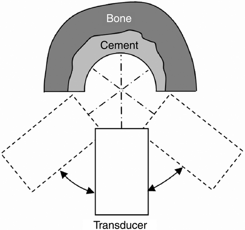
Mirror-transducer combinations are usually not part of the standard equipment for industrial non-destructive testing. Furthermore, once the transducer is fixed in its housing, the focal point cannot be changed. Therefore, the laboratory setup uses a conventional 5-MHz transducer (H5M, Krautkramer, Germany) with perpendicular sound excitation relative to the femur's rotation axis. This setup allows adjustment and optimization of parameters, e.g., moving the focal point and using a different transducer, to be accomplished very simply. To gain ex-vivo access to bone cement samples with this setup, the bones must be cut in half along their rotation axes. The transducer was fixed to a 4D mechatronic positioning system permitting full 360° rotation (resolution: 0.9°) and 3D translative movement. Because of impingement between the transducer and the femur samples, only small sectors of 90–100° could be used for scanning (). In all trials, water was used as a coupling medium between the cement and the transducer.
Figure 1. Top view of the schematic measurement setup for ultrasound scanning.
Ex-vivo measurements
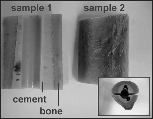
To evaluate the system's accuracy, ex-vivo investigations of the distal part of a proximal human femur were performed. After being rasped with surgical instruments, the femur was prepared with bone cement mixed using the same vacuum system as mentioned earlier. After the cement had cured, a 10-mm hole was drilled in the direction of the femoral rotation axis. The samples were then cut in half to enable access by the measurement setup (). Both femur halves (samples 1 and 2) were CT scanned (0.24 mm resolution; 0.5 mm distance; 0.5 mm thickness). The contours of the bone cement were segmented manually in all CT slices and 3D voxel models were reconstructed using a linear interpolation approximation. Later, the voxel model served as a ground truth. The samples were then scanned with ultrasound using the proposed measurement setup. The angle of scanning was 90° for a single slice. An overall height of 4 mm was scanned for each femur half (slice distance: 0.5 mm).
Figure 2. Ex-vivo samples after preparation with bone cement, drilling and bisection.
The accuracy evaluation of the measured ultrasound data was performed by ICP matching of the pre-filtered ultrasound dataset (∼8000 points) to the corresponding CT dataset and calculation of the residual median distance error between the corresponding data sets Citation[32]. Prior to each ICP matching, an initial point-to-point pre-registration using prominent landmarks (the upper and lower edges of the inner contour of the drilling inside the bone cement) in each of the corresponding data sets was accomplished Citation[33]. Each ICP registration was performed 5 times, using slightly varying pre-registrations. The resulting transformations were compared and deviations calculated to validate the registration results.
Interface detection algorithm
The intention of the detection algorithm is to find the reflection points of the water-cement and cement-bone interfaces and to calculate the 3D coordinates of these points relative to a reference coordinate system. In the case of the proposed measurement setup, the coordinate system of the bone was fixed to the coordinate system of the 4D mechatronic positioning device and therefore no additional tracking device was needed. The same principle could be used for intra-operative scanning in combination with robot-assisted cement removal. In this case, the coordinate system of the scanning device has to be in a fixed and known position relative to the robot and the femur Citation[34].
Because of the very high attenuation of bone for frequencies above 1 MHz, no significant echoes are expected from beyond the cement-bone interface Citation[23]. Each A-mode HF signal (A-line) was processed using special signal-processing algorithms. To improve the signal-to-noise ratio, coded signal excitation using pseudo chirps was used. Each HF signal was processed by applying a mismatched filter to compress the signal and reduce sidelobes. After filtering, the envelope was calculated and a maxima detection algorithm started to find both interfaces (water-cement and cement-bone). A thresholding was used to filter unwanted maxima. The detection algorithm also included a plausibility check to filter outliers using neighborship information and the gradient of change. For thickness calculations, the measured longitudinal propagation speed of vacuum-manufactured bone cement was chosen. The sound velocity in water was 1483 m/s.
Results
Visual inspection of the cement slices showed a higher concentration of pores inside samples manufactured without use of a vacuum system. The velocity for the longitudinal propagation of sound waves in pure acrylic PMMA is typically in the range of 2680–2800 m/s. In comparison, the measured values for bone cement differed according to the manufacturing technique. Using a vacuum system yielded 2640 m/s for the longitudinal propagation velocity, whereas the velocity for the non-vacuum-system probes decreased to 2320 m/s (). Furthermore, sound attenuation increased from 1.5 dB/cm/MHz to 4.1 dB/cm/MHz in the non-vacuum samples (). The reflected signal became noisier in the non-vacuum samples, most likely as a result of scattering by small pores. In the reflection coefficients calculated by using the measured values for density and speed of sound are presented. In the case of the cement-bone interface, mean impedance values for cortical bone were chosen.
Table I. Mean values for longitudinal velocity and attenuation in bone cement, measured at 5 MHz.
Table II. Interface reflection coefficients for different cement manufacturing techniques.
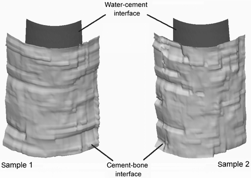
Signal detection was possible for almost all measured A-lines (>96%). The deviations between the calculated translation vectors of all five independent ICP transformations were less than one voxel (<0.23 mm) for both femur halves. After the filtering process, median deviations of 0.15 mm (1st quartile 0.11 mm; 3rd quartile 0.25 mm) for sample 1 and 0.15 mm (1st quartile 0.11 mm; 3rd quartile 0.24 mm) for sample 2 were observed between the cement-bone interfaces of ultrasound datasets and the ground truth (CT data). Only approximately 4% of all calculated deviation values were greater than 0.5 mm. The small interquartile distances (sample 1: 0.14 mm; sample 2: 0.13 mm) strengthen the assumption of a low number of residual outliers. The corresponding results for the water-cement interfaces were 0.13 mm (1st quartile 0.1 mm; 3rd quartile 0.17) for sample 1 and 0.11 mm (1st quartile 0.09 mm; 3rd quartile 0.14 mm) for sample 2 (). From the ultrasound data, a 3D surface of both interfaces could be reconstructed (). This information could be used for online visualization and guidance during navigated, manual cement removal or for robot-assisted milling Citation[34].
Figure 3. Median, 1st and 3rd quartile and maximum deviations between the ultrasound dataset and the manually segmented CT data after ICP matching.
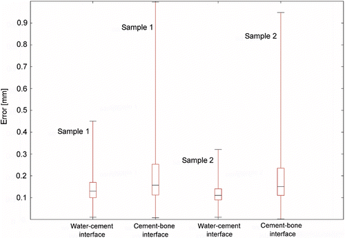
Figure 4. Three-dimensional surface reconstruction of the water-cement and cement-bone interfaces after ultrasound scanning and filtering of samples 1 and 2.
Discussion
The main intentions of this study were to describe the principles of A-mode ultrasound-based detection of bone cement in RTHR and to develop an easy-to-handle laboratory setup for ex-vivo investigation of the distal part of a cemented femur.
The investigation of the ultrasound-specific properties of bone cement demonstrated that different manufacturing techniques must be taken into account when calculating the bone-cement interface. Mixing of cement without using a vacuum system results in pores of varying size forming inside the cement, which has an impact on the longitudinal propagation speed of sound. In a case where the cement manufacturing technique used is unknown, a mean value of 2480 m/s for longitudinal sound propagation should be chosen. As a first approximation, the worst-case measurement error would increase by ∼6% at the cement-bone interface, which seems to be tolerable in RTHR. Due to the presence of micropores inside the cement, a higher attenuation can be investigated. In the case of an expected maximum cement thickness of 12 mm, the attenuation would be in the region of 50 dB (fC = 5 MHz), not considering the reflection losses at both interfaces. Furthermore, the additional noise impact makes detection of the bone-cement interface more challenging. However, vacuum systems have now been used during cement mixing for more than a decade Citation[36], so micropores in the cement should be reduced in the majority of prostheses implanted during this period.
The first ex-vivo trials demonstrate that detection of the water-cement interface as well as the cement-bone interface is possible with high accuracy, as predicted by our calculated reflection coefficients for both interfaces (). In cases where a vacuum system was used during cement preparation, the trials showed a very good correlation between ultrasound-detected interface points and manually segmented CT data. The calculated 3D surface information can be used either for computer navigated manual cement removal by a surgeon, or for automatic removal by a miniaturized robot Citation[34]. Whereas a navigated, freehand cement removal is more like the conventional technique and may be more accepted by surgeons, using the system in combination with a miniaturized robot offers several advantages. It eliminates the need for an additional optical tracking system and consequently increases the overall accuracy. Moreover, a robotic system offers higher precision, and the patient should benefit from the expected decrease in operation time.
As a first approximation we used a round prosthesis design in this study. Using differently shaped implants will cause an additional interface detection error for the cement-bone boundary due to refraction at the water-cement interface, according to the shape of the prosthesis, and on the refraction coefficient at the water-cement interface. The latter effect could be reduced by use of a coupling medium with a higher sound velocity than water. Furthermore, a priori knowledge of the shape of the implanted prosthesis could be used to reduce refraction artefacts.
In our current work we are focusing on the development of a mechatronic scanning device capable of full 360° detection using a miniaturized ultrasound tranducer and an optimized ultrasound hardware design. Integration into a new 5D robot module, which offers interfaces for ultrasound devices and milling instruments, is also part of our ongoing work. Future research will include optimization of signal-processing and detection algorithms, as well as reduction of refraction artefacts.
Acknowledgments
This project has been funded in part by the German Federal Ministry of Education and Research (BMBF) within the framework of the research program SOMIT “Sanftes Operieren mit innovativer Technik”, through grants BMBF 01EQ0402 and BMBF 01EQ0424, and by the Medical Faculty of the University Clinic Aachen, RWTH Aachen, START project.
References
- Wirtz DC, Niethard FU. Ursachen, Diagnostik und Therapie der aseptischen Hüftendoprothesenlockerung – eine Standortbestimmung. Z Orthopädie 1997; 135(4)270–280
- Malchau H, Herberts P, Eisler T, Garellick G, Soderman P. The Swedish Total Hip Replacement Register. J Bone Joint Surg Am 2002; 84-A(Suppl 2)2–20
- Malchau H. Prognosis of total hip replacement: Update and validation of results from the Swedish National Hip Arthroplasty Registry. Proceedings of the 67th Annual Meeting of the American Academy of Orthopaedic Surgeons. Orlando, FL March 2000; 1979–1998
- Li PL, Ingle PJ, Dowell JK. Cement-within-cement revision hip arthroplasty: Should it be done?. J Bone Joint Surg Br 1996; 78(5)809–811
- Taylor RH, Joskowicz L, Williamson B, Gueziec A, Kalvin A, Kazanzides P, Van Vorhis R, Yao J, Kumar R, Bzostek A, Sahay A, Börner M, Lahmer A. Computer-integrated revision total hip replacement surgery: Concept and preliminary results. Med Image Anal 1999; 3(3)301–319
- Sanders R, Koval K, DiPasquale T, Schmelling G, Stenzler S, Ross E. Exposure of the orthopaedic surgeon to radiation. J Bone Joint Surg 1993; 75-A(3)326–330
- Mehlman C, DiPasquale T. Radiation exposure to the orthopaedic surgical team during fluoroscopy: How far away is far enough?. J Orthop Trauma 1997; 11(6)392–398
- Lee CL, Roberts C, Litsky AS. Laser ablation of dyed acrylic bone cement. Lasers Surg Med 1997; 20(3)280–289
- Zimmer M, Klobl R, De Toma G, Jansson V, Refior HJ, Heimkes B, Kuhne JH. Bone cement removal with the excimer laser in revision arthroplasty. Arch Orthop Trauma Surg 1992; 112(1)15–17
- Scholz C, Matthes M, Kar H, Boenick U. Removal of bone cement with laser. Biomed Technol (Berl) 1991; 36(5)120–128
- Schmidt J, Nordmann K. Removal of bone cement from the femoral canal using an acoustic emission-controlled milling device. Medical and Biological Engineering and Computing 1994; 32(3)258–260
- Schwaller CA, Elke R. Cement removal with ultrasound in revision or total hip prosthesis. Der Orthopäde 2001; 30(5)310–316
- Honnart F. Use of ultrasound for the removal of cement in hip prosthesis reoperations. Rev Chir Orthop Reparatrice Appar Mot 1996; 82(2)171–174
- Park SH, Park JB, Weinstein JN, Loening S. Application of extracorporeal shock wave lithotripter (ECSWL) in orthopedics. I. Foundations and overview. J Appl Biomater 1991; 2(2)115–126
- Schreurs BW, Bierkens AF, Huiskes R, Hendrikx AJ, Slooff TJ. The effect of the extracorporeal shock wave lithotriptor on bone cement. J Biomed Material Res 1991; 25(2)157–164
- May TC, Krause WR, Preslar AJ, Smith MJ, Beaudoin AJ, Cardea JA. Use of high-energy shock waves for bone cement removal. J Arthroplasty 1990; 5(1)19–27
- Schmidt J, Porsch M, Hackenbroch MH, Koebke J, Brimmers P. Modified intracorporeal lithotripsy for cement removal in hip prosthesis exchange operations: Experimental principles. Z Orthopädie 1998; 136(1)44–49
- Koster G, Willert H, Buchhorn GH. Endoscopy of the femoral canal in revision arthroplasty of the hip. A new method for improving the operative technique and analysis of implant failure. Arch Orthop Trauma Surg 1999; 119(5–6)245–252
- Mah ET, Bradley CM. Arthroscopic removal of acrylic cement from unreduced hip prosthesis. Aust N Z J Surg 1992; 62(6)508–510
- Chen WM, McAuley JP, Engh CA, Jr, Hopper RH, Engh CA. Extended slide trochanteric osteotomy for revision total hip arthroplasty. J Bone Joint Surg Am 2001; 83-A(7)1107
- MacDonald SJ, Cole C, Guerin J, Rorabeck CH, Bourne RB, McCalden RW. Extended trochanteric osteotomy via the direct lateral approach in revision hip arthroplasty. Clin Orthop Rel Res 2003; (417): 210–216
- de la Fuente M, Ohnsorge JA, Schkommodau E, Jetzki S, Wirtz DC, Radermacher K. Fluoroscopy-based 3-D reconstruction of femoral bone cement: A new approach for revision total hip replacement. IEEE Trans Biomed Eng 2005; 52(4)664–675
- Duck FA. Physical properties of tissue. Academic Press, London 1990
- Maurer CR, Jr, Gaston RP, Hill DL, Gleeson MJ, Taylor MG, Fenlon MR, Edwards PJ, Hawkes DJ. AcouStick: An optically tracked A-mode ultrasonography system for registration in image-guided neurosurgery. Stereotact Funct Neurosurg 1999; 72(2–4)143–144
- Moulder C, Sati M, Wentkowski MV, Nolte LP. A transcutaneous bone digitizer for minimally invasive registration in orthopedics: A real-time focused ultrasound beam approach. Comput Aided Surg 2003; 8(3)120–128
- Heger S, Portheine F, Ohnsorge JA, Schkommodau E, Radermacher K. User-interactive registration of bone with A-mode ultrasound. IEEE Eng Med Biol Mag 2005; 24(2)85–95
- Cysewska-Sobusiak A., Sowier A., Skrzywanek P. Application of rotating EUS micro-probes for deep penetration of upper gastrointestinal tract. Proceedings of IEEE Sensors. ViennaAustria October 2004; Vol 3: 1492–1495
- Horas U, Seidel P, Heiss C, Kilian O, Dingeldein E, Schnettler R. Vacuum mixing systems for bone cement completion – comparison of different systems. Z Orthopaedie und ihre Grenzgebiete 2002; 140(6)603–610
- Wang JS, Franzen H, Jonsson E, Lidgren L. Porosity of bone cement reduced by mixing and collecting under vacuum. Acta Orthop Scan 1993; 64(2)143–146
- Lahav A, DiMaio FR. Evaluation of a new power-operated PMMA vacuum mixing and delivery system for cemented femoral stem insertion. Orthopaedics 2004; 27(1)57–58
- American Society for Gastrointestinal Endoscopy. Role of endoscopic ultrasonography. Gastrointest Endosc 2000; 52(6)852–859
- Besl PJ, McKay ND. A method for registration of 3-D shapes. IEEE Trans Pattern Anal Machine Intell 1992; 14(2)239–256
- Horn BKP. Closed-form solution of absolute orientation using unit quaternions. J Opt Soc Amer A 1987; 4(4)629–642
- Hahndorff M, de la Fuente M., Wirtz DC., Radermacher K. Development of a new miniaturized robotic device for the removal of femoral bone cement. Proceedings of the 5th Annual Meeting of the International Society for Computer Assisted Orthopaedic Surgery (CAOS-International), F Langlotz, BL Davies, D Schlenzka, HelsinkiFinland June 2005; 138–139
- Krautkrämer J, Krautkrämer H. Werkstoffprüfung mit Ultraschall. Springer, Berlin 1986
- Wixson RL. Do we need to vacuum mix or centrifuge cement?. Clin Orthop Rel Res 1992, 285: 84–90