Abstract
Objective: The purpose of this study was to propose our CT-based planning approach for knee arthroplasty on the basis of the femoral flexion-extension (FE) axis, and to evaluate whether this approach was valid by comparing the results with those obtained using conventional anterior-referenced planning.
Materials and Methods: Virtual implantation of a sagittal single-radius component was performed in 34 normal knees. The transepicondylar axis (TEA) was identified as the FE axis, and was modified in the coronal plane to intersect the femoral mechanical axis at a right angle, if necessary. The implant was then selected that had a radius closest to the distance between the modified TEA and the distal condyle end. The implant position and size were compared for the two plans.
Results: In almost all cases, slight modification of the TEA was required. However, there was no significant change in the distance from the TEA to the posterior and distal condyles. In comparison to the results obtained with our planning approach, the conventional plan resulted in antero-superior deviation of the implant sagittal center to the FE axis and/or selection of a larger size of prosthesis.
Conclusion: Although the TEA must be modified slightly when referencing it as the FE axis, our planning approach may be valid for femoral single-radius components because the single axis of the component could be matched with the FE axis.
Introduction
Computer assisted systems have been reported to be useful in achieving proper and highly reproducible coronal alignment in total knee arthroplasty (TKA). There are several types of computer assisted systems in use, including imageless systems Citation[1], Citation[2] and CT-based systems Citation[3–5]. Although CT-based systems require more preoperative time for planning and cumbersome intraoperative steps for registration, they can provide detailed 3D anatomical information regarding sagittal and axial alignment with respect to the transepicondylar axis (TEA) Citation[6], which is sometimes very difficult to identify intraoperatively Citation[2]. Moreover, multiplanar images reconstructed from the CT data of each patient and CAD files of available implants help determine the size and position of the implants to be used. The correct size and positioning of the femoral component is critical for flexion-extension ligament balancing in TKA.
In CT-based preoperative planning, a 3D anatomical reference of the femur must be defined in order to measure the position and orientation of the femoral components. However, there are few reports showing how to define a three-dimensionally concomitant reference for the femur based on CT images. According to conventional wisdom in TKA, it has been generally accepted that the mechanical axis through the femoral head center and the ankle joint center should pass through the knee joint center in the coronal plane Citation[7], Citation[8]. It has also been suggested that the rotational axis of the femoral component should be parallel to the TEA Citation[6], Citation[9], thereby resulting in optimum patellofemoral tracking, avoiding lift-off in flexion, and minimizing femoro-tibial wear Citation[10]. Sagittal alignment has been circumstantially determined based on the distal femoral canal axis or the anterior femoral cortex when the coronal alignment was determined Citation[11]. The implant size has also been determined based on the antero-posterior diameter of the distal femur Citation[12]. This size selection can be affected by the sagittal alignment, however, leading to a deviation of the implant center from the original distal femoral knee center. Specifically, the deviation of the component's knee center may lead to changes in the contour of the distal femoral condyle, which in turn affects the postoperative flexion-extension gap of the knee joint.
Some biomechanical or anatomical studies have shown that the knee moves around the single flexion-extension axis positioned in the posterior condyles, which is approximated by the TEA Citation[13–17]. Therefore, we hypothesized that the center of the knee in the distal femur could be a midpoint of both distal femoral condyles on the TEA. We also hypothesized that the position and sagittal alignment of femoral components could be determined by the femoral knee center, the femoral mechanical axis through the femoral head center and the knee center, and the TEA, while maintaining the flexion-extension balance. However, a modification of the TEA may be necessary because the femoral mechanical axis and the TEA may not intersect at a right angle.
The objectives of this study were to propose our CT-based planning for TKA on the basis of the femoral flexion-extension (FE) axis, to evaluate whether the modification of the TEA was significant when the TEA axis was identified as the FE axis, and finally to evaluate whether our planning approach was valid by comparing the femoral component size and position specified using our CT-based planning method with those obtained using a simulated conventional method.
Material and methods
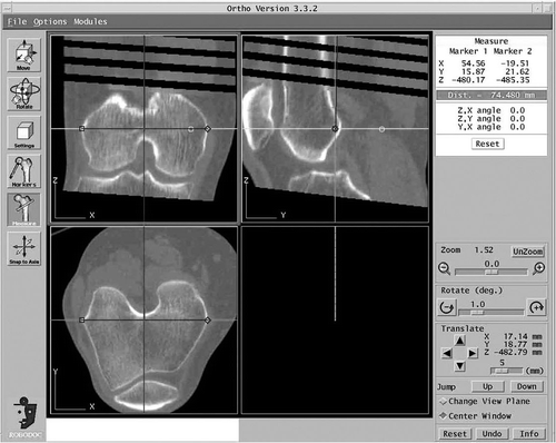
CT data was obtained for 34 knees of 29 volunteers. These volunteers comprised 4 men and 25 women (mean age 69 years; range 60–75) who had undergone CT scans in connection with diseases not involving the knee and had no symptoms and no radiological abnormalities. The CT data were transferred to ORTHODOC, which is the preoperative planning workstation of the ROBODOC system (Integrated Surgical Systems, Davis, CA) for virtual implantation (). ORTHODOC provides multiplanar reconstructed images from CT data in three orthogonal planes, which can be moved, rotated and zoomed as needed. ORTHODOC also allows measurement of the angle between any designated lines and the distances between any points in each reconstructed plane.
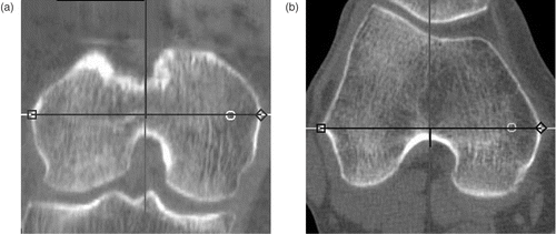
Scorpio posterior cruciate-substituting femoral components (Stryker Howmedica Osteonics, Allendale, NJ) were used for the virtual implantations. The Scorpio femoral condyle has a single radius of curvature in the sagittal plane with the center located close to the TEA Citation[18], Citation[19]. Using ORTHODOC, the TEA was determined by connecting the most prominent points of both the medial epicondyle and the lateral epicondyle (). Berger et al. described two different definitions for the TEA: one between the medial and lateral epicondylar crest (the clinical epicondylar axis), and the other between the sulcus of the medial epicondyle and the crest of the lateral epicondyle (the surgical epicondylar axis) Citation[6]. Although the shape of the medial epicondyle resembles a horseshoe Citation[6], Citation[20], it is not detectable in approximately 30% of examined knees Citation[21], Citation[22]. Thus, we adopted the clinical epicondylar axis in order to standardize the TEA.
Figure 2. The transepicondylar axis was determined by connecting the most prominent points of both the medial and lateral epicondyles in both the coronal plane (a) and the axial plane (b).
The femoral mechanical axis (FMA) was defined as a line through the center of the femoral head and the midpoint between the medial and lateral ends of the TEA in the distal condyle, which was defined as the “knee center”. The axial plane was defined as a plane perpendicular to the FMA. The coronal plane was determined as a plane through the FMA and the TEA. The sagittal plane was defined as a plane which was perpendicular to the coronal plane through the FMA. When the TEA did not intersect the FMA at a right angle on the coronal plane, a modified TEA was determined by rotating the TEA around the knee center in the coronal plane until it was perpendicular to the FMA. This process was done automatically in ORTHODOC and the angle of rotation was recorded. To evaluate how close the modified TEA was to the FE axis, the distances from the modified TEA to the medial and lateral condyle contours on the coronal plane (distally) and axial plane (posteriorly) were measured in each knee. We investigated whether the correlation between these distal and posterior distances was changed as a result of the modification.
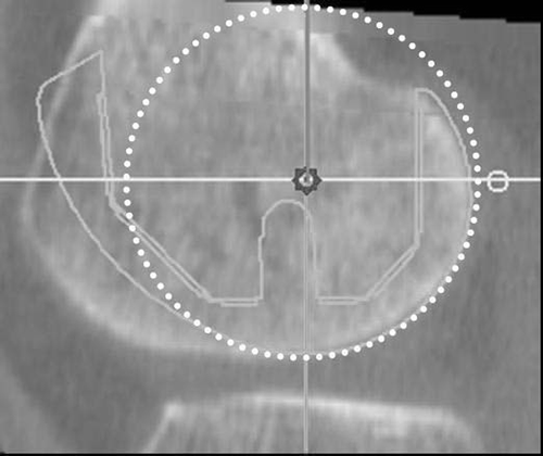
Since the Scorpio femoral component has the sagittal single-radius design, the implant size was determined according to the radius that was closest to the distance from the modified TEA to the distal border of the lateral femoral condyle. The lateral side was selected because the lateral condyle was generally smaller than the medial condyle Citation[16], resulting in the avoidance of a possible gap between the inner margin of the implant and the bone of the lateral condyle. The femoral component was then virtually implanted with the modified TEA coinciding with the radial axis of the femoral component ().
Figure 3. Virtual implantation of the femoral component. The implant size was selected according to the radius (shown as a circle) that was closest to the distance between the TEA (the center of the two orthogonal axes in this view) and the distal condyle border in the lateral condyle.
When the antero-superior apex of the femoral component dug into the anterior cortex of the femur, the femoral component was flexed around the modified TEA to avoid creation of a notch, which has been implicated as one factor contributing to periprosthetic femoral fracture Citation[23] (). If a gap between the apex and the anterior cortex occurred, the implant was rotated into extension until contact was obtained between the anterior cortex and the matching surface of the prosthesis in order to have firm fixation (). This method of virtual implantation was defined as the modified TEA-dependent method.
Figure 4. Flexion of component. When the antero-superior apex of the femoral component dug into the anterior cortex of the femur (a), the femoral component was flexed around the TEA to avoid creation of a notch (b).
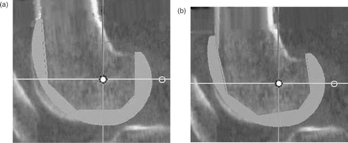
Figure 5. Extension of component. When a gap occurred between the apex and the anterior cortex (a), the implant was rotated into extension until contact was obtained between the anterior cortex and the matching surface of the prosthesis (b).
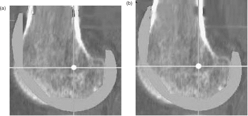
Virtual implantation according to the conventional method using anterior referencing was performed as follows. The femoral component was aligned in accordance with the mechanical axis in the coronal plane, the modified TEA in the axial plane, and the distal femoral shaft axis in the sagittal plane. The size of the component was determined by the antero-posterior distance in the sagittal plane. The component was placed as the distal contour of the lateral condyle matched to the original bony contour. The position of the component was moved slightly in an antero-posterior direction to avoid the anterior notch. We measured the difference in position of the prosthesis centers on a projected sagittal plane for these two implantation methods. For statistical analysis the Mann-Whitney U-test was used, with p < 0.05 considered as statistically significant.
Results
The average tilt angle required for the TEA to be perpendicular to the femoral mechanical axis was −0.1° (95% confidence interval [CI]; range: −1.1 to 0.8°). In the lateral condyle, the average distance from the modified TEA to the condyle borders was 22.0 mm (95% CI; range: 21.4 to 22.8 mm) distally, and 20.9 mm (95% CI; range: 20.2 to 21.4 mm) posteriorly. Medially, the distance from the modified TEA to the joint line averaged 25.4 mm (95% CI; range: 24.5 to 26.2 mm) distally, and 26.0 mm (95% CI; range: 25.0 to 26.9 mm) posteriorly. The difference between these distal and posterior distances (subtracting distal distance from posterior distance) in the lateral and medial condyles of each patient was, on average, 1.13 mm (95% CI; range: 0.3 to 2.0 mm) and −0.57 mm (95% CI; range: −2.1 to 1.0 mm), respectively, before the modification, and 1.20 mm (95% CI; range: 0.4 to 2.0 mm) and −0.63 mm (95% CI; range: −2.1 to 0.9 mm), respectively, after the modification. There was no statistical significance to the differences between these distal and posterior distances before and after the modification (lateral condyle: p = 0.71; medial condyle: p = 0.92).
Rotation of the femoral component around the modified TEA was required to avoid notching of the femur in all but two cases. In those two cases, the sagittal alignment of the femoral component coincided with the mechanical axis. In no case did the femoral component need to be extended to avoid creation of an anterior gap. On average, the ideal position of the femoral component was 6.5° (95% CI; range: 4.9 to 8.1°) of flexion around the modified TEA to the FMA. The average angle between the distal femoral shaft axis and the FMA in the sagittal plane was 0.9° (95% CI; range: 0.5 to 1.2°).
Comparison of the results of virtual implantation using our CT-based method and the conventional method showed differences in the position and flexion angle of the femoral component. With the conventional method, the position of the center of the prosthetic condyle in the sagittal plane, which included the midpoint of the TEA, was shifted anteriorly or antero-superiorly from the modified TEA, while our method based on the modified TEA achieved coincidence of the flexion-extension axis of the prosthetic condyle with the modified TEA. The average distance of the prosthetic knee center from the modified TEA was 2.7 mm (95% CI; range: 2.1 to 3.2 mm) with the conventional method. The difference between the positions of the prosthetic knee center obtained with the two methods was statistically significant (p < 0.0001). With the conventional method, the position was not shifted in only 3 of the 34 cases. There was also a difference in the size of the femoral component selected in 22 of the 34 cases: In 14 cases an increase of one size was required with the conventional method, and in 8 cases an increase of two sizes was required. There was statistically significant difference in the size of the implant selected (p < 0.0001).
Discussion
As some biomechanical and anatomical reports have shown that the knee moves around the single flexion-extension axis which can be approximated by the TEA Citation[13–17], we hypothesized that it was reasonable to use the TEA as the FE axis of femoral components in CT-based preoperative TKA planning. To align the femoral component to the FMA, the TEA should intersect with the FMA perpendicularly at the midpoint of the TEA in the distal femoral condyle. However, the TEA in the coronal plane was not perpendicular to the FMA in 85% of the cases in the present study. To address this issue, slight modification (−0.1° degrees on average) of the TEA was necessary to make the FE axis perpendicular to the FMA. Although one potential problem arising from the modification of the TEA might be flexion-extension gap imbalance due to changes in the distances from the modified TEA to the condyle on the coronal plane, there was no significant difference between the distal and posterior distance ratio from the TEA to the condyle before and after the modification.
In our CT-based planning method, the femoral component had to be placed with an average of 6.5° of flexion to avoid anterior notching as the center of the implant was matched with the modified TEA. We believe that this slight flexion had no adverse effect, because the prosthetic center was not deviated from the femoral knee center and the relation necessary to retain the posterior and distal contour of the femoral condyle was not changed.
Compared with our plan, the sagittal center of the implant shifted anteriorly or antero-superiorly when using the conventional planning method, and larger size implant components were selected. Because the angle distance between the distal femoral shaft axis and the FMA in the sagittal plane was not significant, we suggest that the difference in the implant position and size selected by the two plans derives from the different methods of femoral templating in the sagittal plane. In our plan, the antero-posterior distance of the femoral component in the sagittal plane can be adjusted by flexion of the implant to match the implant center with the modified TEA. In the conventional approach, the antero-posterior distance of the femoral component in the sagittal plane can only be adjusted by increasing the size of the prosthesis in order to prevent anterior notching and maintain the original contour of the condyle, resulting in the anterior or antero-superior deviation of the implant sagittal center. The clinical effects of such differences in size and sagittal alignment between the two methods are not yet clear. Theoretically, however, selection of a larger size implant may be associated with tight patella tracking in flexion.
There are some limitations in our CT-based planning method. First, we have not validated our CT-based method in real patients with osteoarthritic knees. We validated the method to maintain flexion-extension balance by measuring the distal and posterior condyle contour match to the implant. Further clinical studies to measure the flexion-extension gap balance after the femoral cuts based on this CT-based planning for TKA are necessary to understand the optimal 3D preoperative planning for TKA. Second, we cannot deny a possibility that the different results with the two methods depended on the design of the single-radius femoral component used. Of the various components for use with ORTHODOC, there was only one sagittal single-radius component available, although we would like to investigate other sagittal single-radius components in this context.
In conclusion, the tilt angle required to modify the TEA to intersect the femoral mechanical axis at a right angle is small. Our CT-based planning method which matches the flexion-extension axis of the single-radius component with the modified TEA can maintain the original contours of the condyle, resulting in maintenance of the flexion-extension balance, though slight sagittal rotation of the femoral component around the modified TEA is needed. In comparison to our CT-based method, the conventional method tends to select a larger size of femoral component, and its flexion-extension axis is shifted slightly antero-superiorly from the modified TEA.
References
- Stulberg SD, Loan P, Sarin V. Computer-assisted navigation in total knee replacement: results of an initial experience in thirty-five patients. J Bone Joint Surg Am 2002; 84-A(Suppl 2)90–98
- Jenny JY, Boeri C. Low reproducibility of the intra-operative measurement of the transepicondylar axis during total knee replacement. Acta Orthop Scand 2004; 75(1)74–77
- Nofrini L, Martelli S, Iacono F. In vivo evaluation of a computer planning system for total knee arthroplasty. Comput Methods Programs Biomed 2004; 73(1)71–81
- Muller W, Bockholt U, Voss G, Lahmer A, Börner M. Planning system for computer assisted total knee replacement. Stud Health Technol Inform 2000; 70: 214–219
- Jakopec M, Harris SJ, Rodriguez y Baena F, Gomes P, Cobb J, Davies BL. The first clinical application of a “hands-on” robotic knee surgery system. Comput Aided Surg 2001; 6(6)329–339
- Berger RA, Rubash HE, Seel MJ, Thompson WH, Crossett LS. Determining the rotational alignment of the femoral component in total knee arthroplasty using the epicondylar axis. Clin Orthop Relat Res 1993; 286: 40–47
- Moreland JR, Bassett LW, Hanker GJ. Radiographic analysis of the axial alignment of the lower extremity. J Bone Joint Surg Am 1987; 69(5)745–749
- Insall JN, Binazzi R, Soudry M, Mestriner LA. Total knee arthroplasty. Clin Orthop Relat Res 1985; 192: 13–22
- Griffin FM, Insall JN, Scuderi GR. The posterior condylar angle in osteoarthritic knees. J Arthroplasty 1998; 13(7)812–815
- Miller MC, Berger RA, Petrella AJ, Karmas A, Rubash HE. Optimizing femoral component rotation in total knee arthroplasty. Clin Orthop Relat Res 2001; 392: 38–45
- Faris PM, Ritter MA, Keating EM. Sagittal plane positioning of the femoral component in total knee arthroplasty. J Arthroplasty 1988; 3(4)355–358
- Townley CO. The anatomic total knee resurfacing arthroplasty. Clin Orthop Relat Res 1985; 192: 82–96
- Hollister AM, Jatana S, Singh AK, Sullivan WW, Lupichuk AG. The axes of rotation of the knee. Clin Orthop Relat Res 1993; 290: 259–268
- Elias SG, Freeman MA, Gokcay EI. A correlative study of the geometry and anatomy of the distal femur. Clin Orthop Relat Res 1990; 260: 98–103
- Churchill DL, Incavo SJ, Johnson CC, Beynnon BD. The transepicondylar axis approximates the optimal flexion axis of the knee. Clin Orthop Relat Res 1998; 356: 111–118
- Stiehl JB, Abbott BD. Morphology of the transepicondylar axis and its application in primary and revision total knee arthroplasty. J Arthroplasty 1995; 10(6)785–789
- Most E, Axe J, Rubash H, Li G. Sensitivity of the knee joint kinematics calculation to selection of flexion axes. J Biomech 2004; 37(11)1743–1748
- D'Lima DD, Poole C, Chadha H, Hermida JC, Mahar A, Colwell Jr, CW. Quadriceps moment arm and quadriceps forces after total knee arthroplasty. Clin Orthop Relat Res 2001; 392: 213–220
- Wang H, Simpson KJ, Chamnongkich S, Kinsey T, Mahoney OM. A biomechanical comparison between the single-axis and multi-axis total knee arthroplasty systems for the stand-to-sit movement. Clin Biomech (Bristol, Avon) 2005; 20(4)428–433
- Griffin FM, Math K, Scuderi GR, Insall JN, Poilvache PL. Anatomy of the epicondyles of the distal femur: MRI analysis of normal knees. J Arthroplasty 2000; 15(3)354–359
- Uehara K, Kadoya Y, Kobayashi A, Ohashi H, Yamano Y. Bone anatomy and rotational alignment in total knee arthroplasty. Clin Orthop Relat Res 2002; 402: 196–201
- Akagi M, Yamashita E, Nakagawa T, Asano T, Nakamura T. Relationship between frontal knee alignment and reference axes in the distal femur. Clin Orthop Relat Res 2001; 388: 147–156
- Lesh ML, Schneider DJ, Deol G, Davis B, Jacobs CR, Pellegrini Jr, VD. The consequences of anterior femoral notching in total knee arthroplasty. A biomechanical study. J Bone Joint Surg Am 2000; 82-A(8)1096–1101
