Abstract
Manipulating small objects such as needles, screws or plates inside the human body during minimally invasive surgery can be very difficult for less experienced surgeons due to the loss of 3D depth perception. Classical navigation techniques are often incapable of providing support in such situations, as the augmentation of the scene with the necessary artificial markers - if possible at all - is usually cumbersome and leads to increased invasiveness. We present an approach relying solely on a standard endoscope as a tracking device for determining the pose of such objects, using the example of a suturing needle. The resulting pose information is then used to generate artificial 3D cues on the 2D screen to provide optimal support for surgeons during tissue suturing. In addition, if an external tracking device is provided to report the endoscope's position, the suturing needle can be directly tracked in the world coordinate system. Furthermore, a visual navigation aid can be incorporated if a 3D surface is intraoperatively reconstructed from the endoscopic video stream or registered from preoperative imaging.
Introduction
Minimally invasive surgery (MIS) requires considerable experience and pronounced skill on the part of the surgeon. One of the main reasons for this lies in the almost complete loss of depth perception, which makes the manipulation of small objects such as needles, screws or plates very difficult. Classical navigation approaches are often of only limited help in such situations, due to the restrictions imposed when using standard tracking techniques. Visual trackers need a direct line of sight, and the dimensions or function of such objects often precludes marker attachment. While magnetic markers with small dimensions exist, the presence of metallic objects in their vicinity severely degrades their accuracy.
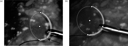
This paper presents a framework for tracking small objects and estimating their pose relying only on a standard, monocular endoscope. As an example of its application, the tracking and pose estimation of a suturing needle is presented; this represents a particularly difficult case due to the ambiguous pose perception, as can be seen in .
Figure 1. Examples of the ambiguity of needle pose perception. (a) Needle tip pointing towards the camera. (b) Needle tip pointing away from the camera.

The resulting pose information is then used to augment the surgeon's view by projecting artificial 3D cues onto the 2D display and hence providing additional support for improved depth perception during suturing. Such augmentation techniques are especially helpful for trainees and less experienced surgeons. The presented approach is general and can be applied to any object of known geometry with minor adaptations of the segmentation and tracking module.
If there is an external tracking device reporting the endoscope's pose, the needle can be fully tracked in a hybrid fashion in the world coordinate system. Finally, if 3D organ surfaces are reconstructed from the endoscopic video stream, or preoperatively generated models are registered to the scene, possible interactions between the tracked object and the anatomy can also be visualized and used as a navigation aid.
Related research
Endoscopic tracking for navigation is a new research area and only a few systems have been proposed in the literature. A hybrid tracking approach used for spine surgery has been presented by Thoranaghatte et al. Citation[1]. In this approach, passive fiducials are attached to the vertebrae and their pose detected by a tracked endoscope. However, the registration of the fiducials with the target anatomy adds another step to the navigation procedure. In the approach of Sauer et al. Citation[2], fiducials are attached to the tools and their 3D pose is measured by a head-mounted monocular camera. The results are presented on a head-mounted display (HMD). Objects without a direct line of sight to the camera cannot be handled by this system. Other approaches to tracking and pose estimation of surgical instruments include structured light endoscopes Citation[3] and ultrasound probes Citation[4]. However, the utility of ultrasound is constrained by the presence of air-filled cavities in the body. An approach based on a standard monocular endoscope for improving depth perception was presented by Nicolaou et al. Citation[5], in which the faint shadows of the tools where artificially rendered into the scene.
In this paper we propose a system for estimating the pose of small colored objects in order to augment the surgeon's view. This method relies only on the standard environment of endoscopic surgery: no modifications of the instruments, such as the attachment of markers, are needed, and only the surface color of the object to be identified needs to be adjusted. This approach enables tracking of these objects in a hybrid fashion, allowing enhancement of existing navigation systems. Our solution relies on several techniques originating in the fields of computer vision and augmented reality, such as object detection and tracking, segmentation, pose estimation, and augmented visualization. In the following paragraphs we will survey available techniques from these areas and explain our specific choices for implementation.
Various different approaches have already been proposed for object detection. However, most of them fail to track the small suturing needle due to specific difficulties such as specularities on the polished metal. Pattern matching as in reference Citation[6] will not work as the object is very small and can be severely occluded. Kernel-based object tracking Citation[7] is not applicable as the relative motion is too fast and the object geometry is not suitable for this kind of technique. The method proposed by Lowe Citation[8] cannot be applied either, as there are no straight lines with well-defined relations. Instead of exploiting geometric features, Krupa et al. used color information Citation[9], color-coding the instruments to be tracked during robotized laparoscopic surgeries. Another approach to tracking color-coded laparoscopic instruments was proposed by Wei et al. Citation[10].
Due to the difficulties described above and the known 3D geometry of the object to be tracked, we decided to use model-based recognition techniques. As the needle is approximately circular, this requires the identification of a corresponding ellipse on the 2D endoscopic image. Numerous methods are available to identify and fit an ellipse to image data, such as those described in references Citation[11], Citation[12], and Citation[13]. However, these approaches are not suitable for our application, as they either require the full ellipse to be visible or they use iterative algorithms which make them inadequate for a real-time application. We face the same problem when using the Hough Transform (HT), which is computationally very expensive as the parameter space has five dimensions for an ellipse. This can be at least partially compensated for by using randomized HT Citation[14], as also applied for ellipse detection Citation[15].
For this project we use the non-iterative closed ellipse fitting approach presented by Fitzgibbon et al. Citation[16]. This method performs best in terms of simplicity, performance and robustness in the presence of noise, which usually degrades the segmented data. It directly exploits the ellipse's properties in its implicit representation, performs a least squares fit to all available points, and is thus computationally very efficient.
Once the ellipse has been detected in the image, the corresponding object pose in three dimensions can be computed. The pose computation for objects in two-dimensional images has been explored based on 2D to 3D point correspondences Citation[17], using textures Citation[18] and from parameterized geometries Citation[19]. Pose computation for different geometric entities such as ellipses, lines, points and their combinations was presented in reference Citation[11]. An example of pose determination for orthopedic implants based on X-ray images can be found in reference Citation[20].
Methods
Tracking a needle in a surgical environment is a challenging task for numerous reasons. First, neither the background nor the camera is fixed. In addition, the surgical scene, composed of different tissues, can experience elastic deformations. The needle can move relatively fast and its motion is unconstrained, resulting in six degrees of freedom (DOF). Even if the motion of a needle is constrained, it becomes largely unpredictable when held by a gripper or when penetrating tissue. The method applied must be robust against significant partial occlusions of the needle, which are unavoidable during the suturing process. Finally, the co-axial illumination yields strong specularities on the background as well as on the object, and the illumination itself is non-uniform.
Considering all these complicating factors, a simplification of the problem could be achieved by applying a matt green finish to the needle. As a consequence, specularities were significantly reduced and segmentation of the needle was greatly facilitated as the surgical scene does not usually contain any green-colored objects.
Needle tracking and pose estimation
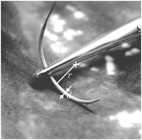
For all experiments, a 10-mm radial distortion corrected endoscope (Panoview Plus, Richard Wolf GmbH, Knittlingen, Germany; http://www.richard-wolf.com/http://www.richard-wolf.de/) with an oblique viewing angle of 25° was used. To avoid interlacing artifacts, a progressive frame, color CCD camera with a resolution of 800 × 600 pixels and 30 fps was used. The camera is calibrated preoperatively by the surgeon without requiring technical assistance Citation[21]. As the endoscope-camera combination provides a depth of field in the range of 30–70 mm, the focal length of the camera can be kept constant during the entire procedure. This avoids the need to recalibrate the system during surgery. The surgical needle (Atraloc, Ethicon Ltd., Edinburgh, UK; http://www.ethicon.com) presents an almost semi-circular shape with a radius r = 8.5 mm and a needle diameter d = 1 mm, as depicted in . Other circular needles can be tracked by simply adapting the radius and the angle of the circle segment, which can be done even intraoperatively.
On start-up, the needle must first pass through an initial rectangular search area of 200 × 200 pixels in the center of the image. Once the needle is found, the tracking and pose estimation starts. The whole algorithm is depicted in and explained in more detail in the following paragraphs.
Color segmentation is applied to the search area, selecting all green pixels. The RGB image is converted to the HSI-color space using Equations 1 to 4, where R, G and B denote the red, green, and blue levels of an RGB image with R, G, B ∈ [0, 1].
with
The saturation is given by
and the intensity by
Then, all pixels within the hue range H ∈ [65°, 160°] are selected. Additional constraints for the saturation (S ≥ 0.15) and intensity (I ≥ 0.06) reduce the specularities and help to remove dark areas. All these values were empirically determined but remained constant throughout all the experiments as they only depend on the camera's white-balance settings. The segmented pixels are then processed by a connected component labeling algorithm where small components of less than a threshold tA = 100 pixels are discarded. This filtering step also eliminates areas resulting from reflections of the needle on the gripper or other specularities. For performance reasons, filtering and labeling are performed in one step. An ellipse is fitted to all remaining components using the method proposed by Fitzgibbon et al. Citation[16].
For increased accuracy, the influence of the lens distortion needs to be removed. As the chosen distortion model Citation[22] is not invertible, an iterative approach is used to reverse the process. This usually requires only two or three iterations to converge and is thus computationally not very expensive. The undistortion algorithm uses the distorted image coordinates xd for the initialization xu,0 = (xu,0, yu,0)T = xd and then iterates as follows:with ri² = xu,i² + yu,i² and k1 and k2 the radial and t1 and t2 the tangential distortion coefficients.
The fitting step computes the center of the ellipse ce = (x0, y0)T, the major and minor axes a and b, and the tilt angle θ, defined as the angle between the major axis a and the x-axis, as shown in . The ellipse center is estimated with sub-pixel accuracy. We further improve the robustness as well as the speed of the segmentation and the fit by checking temporal continuity during the tracking process. The current parameter set pt = (x0, y0, a, b, θ)T is compared to the previously computed one pt−1. A motion vector is computed as mt = ce,t − ce,t−1 and the previous search window is uniformly expanded by 50 pixels. If the new ellipse center is within these bounds and the change in the parameters x0, y0, a and b is below a threshold of tCR = 30%, the new model is regarded as valid. Otherwise, the found ellipse is discarded, the next image acquired, and the ellipse's parameters are estimated under the same conditions as before. As the tilt angle θ can change very rapidly, it is not taken into account for this validation step.
Figure 4. Ellipse and circle parameters. (a) 2D ellipse parameters ce = (x0, y0)T, a,b, θ. (b) Projection of a 3D circle, defined by C = (Xc, Yc, Zc)T, n, to the image plane.

From the identified 2D ellipse parameters, the corresponding 3D circle is computed using the method proposed in reference Citation[23]. This returns the location of the circle center C = (Xc, Yc, Zc)T and the normal n of the plane containing the needle as depicted in . The computation of the needle pose is ambiguous, as illustrated in , and results in two distinct solutions for the center (C1, C2) and two for the normal (n1, n2), giving four possible combinations as the final result. The correct circle center can then be determined by reprojecting both solutions ci = PCi onto the image plane and choosing the one having the smaller Euclidean distance to the previously computed ellipse center ce, di = |ce − ci|, with being the projection matrix of the camera containing its intrinsic parameters.
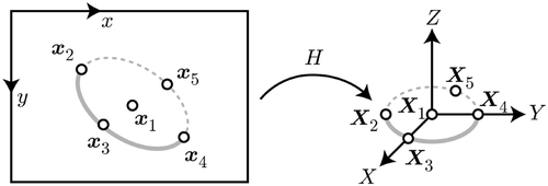
Disambiguation of the needle plane normal is less straightforward. A second pose estimation step based on planar targets like the one for camera calibration Citation[24] is used to determine the correct orientation. While less accurate than the previously described method, the camera pose with respect to a planar target and vice versa can be uniquely computed by establishing the homography between image points and points on the reference needle model, as depicted in . The homography between these two point sets is directly related to the projection matrix PBy setting all reference points’ z-coordinates to 0 (for simplicity of the formulation we assume that they lie in the xy-plane, which can be done without loss of generality) this becomes
Then the homography is defined by the three column vectors h1, h2, and h3:
It is therefore straightforward to extract the two rotation column vectors and the translation of the camera pose:
The sought-after normal of the plane is then given by
with
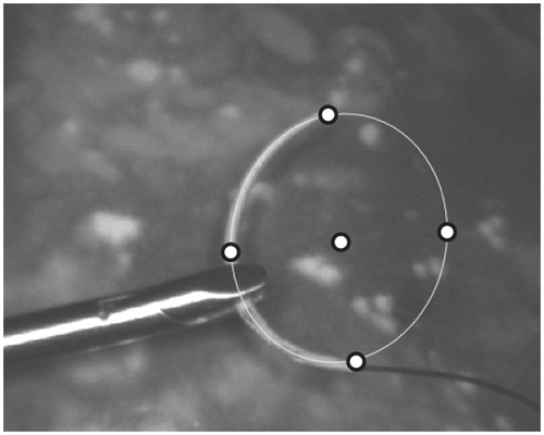
. However, in order to establish a homography, at least four point correspondences are needed. The tip and the tail of the needle, as well as the previously found needle center, provide three such pairs. To generate further data, virtual points are generated on the ellipse, as seen in . For higher numerical stability, a total of five points were used.
Figure 6. The five points used for establishing the homography between the ellipse and the needle model.
The homography estimation can be made more robust by providing real points. This can be achieved by (1) creating at least one additional marker on the needle, such as the colored rings depicted in , or (2) exploiting the fact that the needle is usually held by the gripper at a well-defined, fixed position during suturing (i.e., at approximately one third of the overall needle length closer to the wire) as depicted in . As these points may not always be visible, e.g., due to occlusions while suturing or while passing through a degenerate solution as in , the homography computation as in Equation 16 becomes unreliable. This event can be detected by comparing the values λ1, λ2, λ3, which will vary by more than one order of magnitude in this case. If λ1 > 10λ2 or λ2 > 10λ1, we rely on the assumption of continuous motion, i.e., we select the normal which moves most consistently with the prior motion.
Augmented visualization
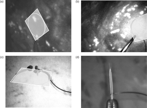
The methods presented above can be used to compensate for the loss of 3D depth perception by providing artificial orientation cues. This does not require any significant adaptation by the surgeon as his working environment remains unchanged. For example, a semi-transparent plane containing the needle can be projected onto the 2D image indicating the relative pose of the needle with respect to the camera, thus resolving the inherent ambiguity, as seen in . The plane is represented by the square enclosing the needle, whose vertices Xi are reprojected onto the image xi = PXi. The square is displayed in a semi-transparent fashion to minimize the loss of information due to occlusion, and its projective distortion indicates which part of the needle is closer to the camera (see ). A degenerate case is illustrated in ; however, the tracking engine recovers quickly from such situations.
Figure 8. Augmented visualization examples. (a) Example visualization of the needle showing the detected ellipse and the plane. (b) Needle held by gripper. (c) Example showing partial occlusion during the suturing process on a phantom mock-up. (d) Degenerate case with the needle plane being almost perpendicular to the image plane.
Hybrid tracking
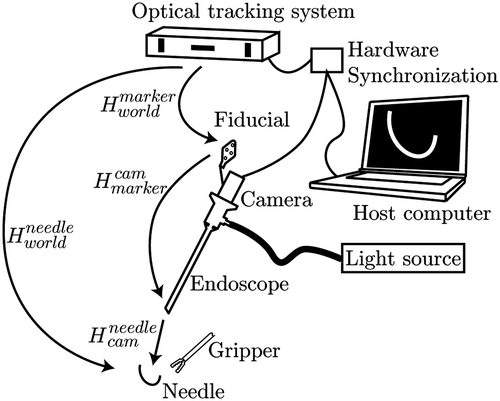
As already mentioned, the system described can be extended to enable 3D object tracking. If the endoscope is tracked externally and the needle pose is computed in the camera coordinate system, as indicated in , the needle pose can be calculated in world coordinates:with
being the transformation relating the camera to the world coordinate system as computed during the calibration process, and
the transformation resulting from the pose estimation process as described in the Needle tracking and pose estimation section.
For these experiments, the camera position is reported using an EasyTrack500 active tracking device (Atracsys LLC., Bottens, Switzerland, http://www.atracsys.comhttp://www.atracsys.com) which provides accurate position (less than 0.25 mm error) and orientation information in a working volume of roughly 50 × 50 × 50 cm3. An external hardware triggering logic enables synchronization of the tracking data with the camera images during dynamic freehand manipulation.
Navigation aid
Even more navigation cues can be integrated if registered 3D data generated from preoperative images such as CT or MRI or intraoperatively acquired 3D organ surfaces (reconstructed, for example, using the endoscopic video stream, as presented in reference Citation[25]) are available and the needle is tracked using the proposed methods. This allows determination of the exact spatial relations between the tracked object and the anatomy. Quantitative distance information, as well as a simplified control of the needle's entry point into the tissue, allows improved suturing quality and surgical gesture efficiency, especially for less experienced surgeons. The involved 3D surfaces can be represented as a triangular mesh Mworld. The intersection of the needle plane πworld with the mesh Mworld defines a lineset l, which can be used to predict the interaction between the tool and the organ, as depicted in .A visibility filter vcam returns those lines from this set that are visible in the current view
with [R, t] being the camera pose in the world coordinate system. The filter vcam casts rays from the camera position to both vertices of each line. If a face is encountered between the camera position and one of the line vertices, this line is set to invisible, as illustrated in .
Figure 10. Lineset examples for the proposed navigation aid. (a) The plane containing the needle is cut with the 3D mesh resulting in a lineset l. (b) The lineset also contains lines on the backside of the 3D model.
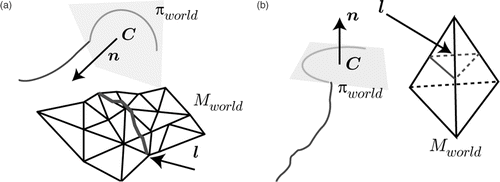
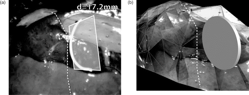
This pessimistic approach may lead to the complete loss of only partially occluded line segments as depicted in . However, this seldom occurs when considering usual organ topography. In rare cases where multiple cutting lines result from this procedure, the solution closer to the needle is selected. While the reconstructed 3D model as shown in is essential for these operations, it remains hidden from the surgeon and the system only presents the final cutting line, overlaid on the endoscopic view. In addition, the distance between the needle and the 3D model can also be displayed.
Figure 12. Navigation aid predicting the location of the interaction between tool and tissue. (a) 2D augmented view with the needle plane, the cutting line and distance information. (b) Internal 3D representation of the same scene showing the 3D model, the disk containing the needle and the 3D cutting line.
Results
The frame-rate for the hybrid tracking is mainly determined by the needle detection and the ellipse fitting process. Both depend on the number of segmented needle pixels, thus the processing time decreases with growing distance between the needle and the camera. In the working range of 30 − 70 mm the system runs in real time with a frame-rate between 15 − 30 fps on a 2.8-GHz Xeon CPU. The frame-rate for the virtual interaction depends on the actual size of the 3D model. For cases presented in our experiments relying on meshes with approximately 500 − 1000 faces, the frame-rate dropped to 10 − 15 fps using a NVidia GeForce FX5700 GPU.
Two test recordings of 2397 frames and 1576 frames were analyzed to quantify the performance of the tracking process. During the first sequence the needle was moved freely in front of the camera and was successfully tracked in 83% of the images. In 4% the needle was found but discarded as the ellipse parameters changed too much and were therefore removed by the validation process. Approximately 3% of the frames were used either prior or during the initialization phase. In the remaining 10% of the images, the needle was outside the field of view of the endoscope. The second sequence simulated a suturing process on an ex-vivo liver. Therefore, the needle was often partially occluded but could still be successfully tracked in 75% of the sequence. An unstable model was reported in 15% of the images and again 3% were used for initialization. The needle was either completely occluded or outside the field of view in the remaining 7% of the images.
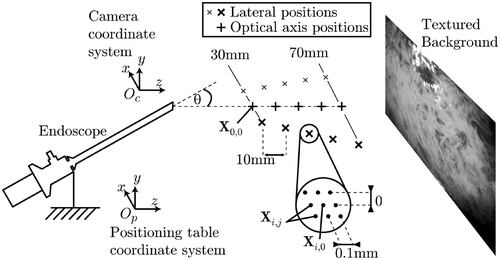
To assess the accuracy of the pose estimation, a 2-DOF positioning table with a resolution of 0.02 mm was used to move the needle to 15 distinct positions Xi,0 with i = 0…14, covering the whole working volume while keeping the needle orientation constant, as shown in . The endoscope was manually aligned to the positioning table such that the optical axis coincided with the table's z-axis. A printed photograph provided an organ-textured background.
As the errors in the x- and y-directions are very similar (both depend mainly on the in-plane resolution of the camera), only the errors in the x- and z-directions are presented here. Around each distinct position Xi,0 eight shifts of 0.1 mm were performed, resulting in the positions Xi,j with j = 1…8. At each of these 135 points the needle position was computed in the camera coordinate system, resulting in the points Yi,j.
To estimate the absolute positional accuracy of the measurements, it is necessary to know the exact transformation between the camera and the world coordinate system. As this ground truth was not available, in the first experiment we only tested how precisely the movement of the needle relative to a selected reference point (X0,0) could be measured. Even though good agreement between the resulting estimates in the camera coordinate system and the actual setting in the world coordinate system does not guarantee correct pose, it nonetheless provides a first guess regarding the accuracy to be expected. For these measurements we used X0,0 in the world coordinate system and the corresponding Y0,0 in the camera coordinate system as the reference points. The distances dX,i,j = |X0,0 − Xi,j| and dY,i,j = |Y0,0 − Yi,j| were calculated over the whole working volume and the statistics of their absolute deviation are summarized in .
Table I. Distance errors.
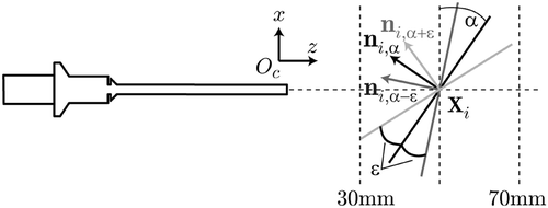
The angular accuracy was similarly quantified by introducing controlled rotations (ε = ±5°) of the needle with respect to the image plane as depicted in . At each position Xi with i = 0…4, the orientation of the needle was computed in the camera coordinate system, resulting in three normal vectors ni,α, ni,α−ε, n,iα+ε. This was performed with the needle being parallel to the image plane (α = 0°), as well as with inclinations of α = 30° and α = 60°.
The normal n0,0, being closest to the camera, was taken as the reference rotation and all others compared directly to this such thatwith βi being the ground-truth angle between two poses. The results are summarized in .
Table II. Angular errors.
While these results were highly encouraging, they cannot fully replace measures of absolute positional accuracy. As the ground truth for the coordinate transformation between the world (i.e., the positioning table) and the camera was not known, we had to estimate it from the actual measurements. To this end, we computed an optimal rigid registration between the point sets Yi,j and Xi,j. Determining the normal to the plane containing the points, the optical axis and a common reference point is sufficient for this purpose. The normal in the positioning table coordinate system Op is simply np = (0, 0, 1)T, the optical axis op = (0, 0, 1)T, and the reference point X0,0 was set to (0, 0, 0)T. In the camera coordinate system centered at Y0,0, the normal nc and the optical axis oc were estimated using a least-squares fitting process. After computing the transformation [R, t] relating both coordinate systems, the positional errors di,j = |Xi,j − (RYi,j + t)| could be calculated as summarized in .
Table III. Distance errors.
We also listed the statistics for the deviations in x, y and z coordinates in . These results clearly overestimate the positional error, as the numbers are distorted by the unavoidable inaccuracies in the estimation of the transformation [R, t].
Table IV. Position errors.
It should be noted that the reported results cannot be interpreted as the overall accuracy that can be achieved by a navigation system. This will be strongly influenced by errors introduced through the camera tracking and the initial registration with the patient's anatomy, which, in our experience, could be up to an order of magnitude larger. In conclusion, we can state that the procedure proposed in this paper will not significantly degrade the performance of the navigation process.
Conclusion
In this paper we have presented a multi-purpose tracking method to handle small man-made objects that can cope with partial occlusions, cluttered background and fast object movement. The proposed system allows real-time tracking of a suturing needle with sub-millimetric accuracy. The needle tracking is very robust and quickly recovers even from full occlusions. Various visualization aids using augmented reality techniques have been implemented, which may help the surgeon to perceive 3D cues from 2D images while still relying on the existing instrumentation. The hybrid tracking can improve navigation systems by offering the possibility of handling small objects hidden in intracorporal cavities.
The parameters were selected experimentally, but could be kept constant during all experiments. The color dependency of the system requires the white balance to be set accurately in advance, a process which has to be integrated into the calibration procedure.
We will concentrate in the future on extending our results to allow tracking and pose estimation for other objects such as screws and plates, leading to a greater flexibility of the system, as well as enabling the simultaneous tracking of multiple objects.
The most important step to come is the clinical validation of the system and the quantification of its impact on the surgeons' performance. In-vitro psychophysical experiments based on surgical simulators (such as box trainers or virtual reality-based devices) are currently planned. Once appropriate performance measures have been identified, these could also be used to evaluate the benefits of the support technology in the operating room by processing the video stream recorded during interventions.
Acknowledgments
This work has been supported by the NCCR Co-Me research network of the Swiss National Science Foundation (http://co-me.ch).
References
- Thoranaghatte RU, Zheng G, Langlotz F, Nolte LP. Endoscope-based hybrid navigation system for minimally invasive ventral-spine surgeries. Comput Aided Surg 2005; 10(5–6)351–356
- Sauer F, Khamene A, Vogt S. An augmented reality navigation system with a single-camera tracker: System design and needle biopsy phantom trial. Proceedings of the Fifth International Conference on Medical Image Computing and Computer-Assisted Intervention (MICCAI 2002), Tokyo, Japan, September 2002. Part II. Lecture Notes in Computer Science 2489, T Dohi, R Kikinis. Springer, Berlin 2002; 116–124
- Fuchs H, Livingston M, Raskar R, Colucci D, Keller K, State A, Crawford JR, Rademacher P, Drake SH, Meyer AA. Augmented reality visualization for laparoscopic surgery. Proceedings of the First International Conference on Medical Image Computing and Computer-Assisted Intervention (MICCAI’98), Cambridge, MA, October 1998. Lecture Notes in Computer Science 1496, WM Wells, A Colchester, S Delp. Springer, Berlin 1998; 934–943
- Novotny PM, Stoll JA, Vasilyev NV, del Nido PJ, Dupont PE, Howe RD. GPU based real-time instrument tracking with three dimensional ultrasound. Med Image Anal 2007; 11(5)458–464
- Nicolaou M, James A, Lo B, Darzi A, Yang GZ. Invisible shadow for navigation and planning in minimal invasive surgery. Proceedings of the 8th International Conference on Medical Image Computing and Computer-Assisted Intervention (MICCAI 2005), Palm Springs, CA, October 2005. Part II. Lecture Notes in Computer Science 3750, JS Duncan, G Gerig. Springer, Berlin 2005; 25–32
- Morimoto T, Kiriyama O, Harada Y, Adachi H, Koide T, Mattausch HJ. Object tracking in video pictures based on image segmentation and pattern matching. Proceedings of the IEEE International Symposium on Circuits and Systems (ISCAS 2005). Kobe, Japan May, 2005; 3215–3218
- Comaniciu D, Ramesh V, Meer P. Kernel-based object tracking. IEEE Trans Pattern Anal Machine Intell 2003; 25(5)564–577
- Lowe DG. Three-dimensional object recognition from single two-dimensional images. Artificial Intell 1987; 31(3)355–395
- Krupa A, de Mathelin M, Doignon C, Gangloff J, Morel G, Soler L, Leroy J, Marescaux J. Automatic 3-D positioning of surgical instruments during robotized laparoscopic surgery using automatic visual feedback. Proceedings of the Fifth International Conference on Medical Image Computing and Computer-Assisted Intervention (MICCAI 2002), Tokyo, Japan, September 2002. Part I. Lecture Notes in Computer Science 2488, T Dohi, R Kikinis. Springer, Berlin 2002; 9–16
- Wei GQ, Arbter K, Hirzinger G. Automatic tracking of laparoscopic instruments by color coding. Proceedings of the First Joint Conference on Computer Vision, Virtual Reality and Robotics in Medicine and Medical Robotics and Computer-Assisted Surgery (CVRMed-MRCAS’97), Grenoble, France, March 1997. Lecture Notes in Computer Science 1205, J Troccaz, E Grimson, R Mösges. Springer, Berlin 1997; 357–366
- Ji Q, Haralick RM. A statistically efficient method for ellipse detection. Proceedings of the International Conference on Image Processing (ICIP 1999). Kobe, Japan October, 1999; 2: 730–734
- Rosin PL, West GAW. Nonparametric segmentation of curves into various representations. IEEE Trans Pattern Anal Machine Intell 1995; 17(12)1140–1153
- Rosin PL, West GAW. Segmenting curves into elliptic arcs and straight lines. Proceedings of the IEEE International Conference on Computer Vision (ICCV 1990). Osaka, Japan December, 1990; 75–78
- Xu L, Oja E. Randomized Hough transform (RHT): basic mechanisms, algorithms, and computational complexities. CVGIP: Image Understanding 1993; 57(2)131–154
- McLaughlin RA. Randomized Hough transform: Improved ellipse detection with comparison. Pattern Recognition Letters 1998; 19(3–4)299–305
- Fitzgibbon AW, Pilu M, Fisher RB. Direct least squares fitting of ellipses. Proceedings of the 13th International Conference on Pattern Recognition (ICPR 1996). Vienna, Austria September, 1996; 253–257
- Haralick RM, Joo H, Lee C, Zhuang X, Vaidya VG, Kim MB. Pose estimation from corresponding point data. IEEE Trans Systems Man Cybernetics 1989; 19(6)1426–1446
- Rosenhahn B, Ho H, Klette R. Texture driven pose estimation. Proceedings of the International Conference on Computer Graphics, Imaging and Visualization (CGIV’05). Beijing, China July, 2005; 271–277
- Lowe DG. Fitting parameterized three-dimensional models to images. IEEE Trans Pattern Anal Machine Intell 1991; 13(5)441–450
- Burckhardt K, Dora C, Gerber C, Hodler J, Székely G. Measuring orthopedic implant wear on standard radiographs with a precision in the 10 µm range. Med Image Anal 2006; 10(4)520–529
- Wengert C, Reeff M, Cattin PC, Székely G. Fully automatic endoscope calibration for intraoperative use. Proceedings of Bildverarbeitung für die Medizin (BVM 2006). Hamburg, Germany March, 2006; 419–423
- Heikkilä J, Silven O. A four-step camera calibration procedure with implicit image correction. Proceedings of the IEEE Computer Society Conference on Computer Vision and Pattern Recognition (CVPR 1997). Puerto Rico, San Juan June, 1997; 1106–1112
- De Ipiña DL, Mendonça PRS, Hopper A. TRIP: A low-cost vision-based location system for ubiquitous computing. Personal Ubiquitous Computing 2002; 6(3)206–219
- Zhang ZY. Flexible camera calibration by viewing a plane from unknown orientations. Proceedings of the 7th IEEE International Conference on Computer Vision (ICCV 1999). Kerkyra, CorfuGreece September, 1999; 1: 666–673
- Wengert C, Cattin PC, Duff JM, Székely G. Markerless endoscopic registration and referencing. Proceedings of the 9th International Conference on Medical Image Computing and Computer-Assisted Intervention (MICCAI 2006), Copenhagen, Denmark, October 2006. Part I. Lecture Notes in Computer Science 4190, R Larsen, M Nielsen, J Sporring. Springer, Berlin 2006; 816–823
