Abstract
The technology for localization of surgical tools with respect to the patient's reference coordinate system in three to six degrees of freedom is one of the key components in computer aided surgery. Several tracking methods are available, of which optical tracking is the most widespread in clinical use. Optical tracking technology has proven to be a reliable method for intra-operative position and orientation acquisition in many clinical applications; however, the accuracy of such localizers is still a topic of discussion.
In this paper, the accuracy of three optical localizer systems, the NDI Polaris P4, the NDI Polaris Spectra (in active and passive mode) and the Stryker Navigation System II camera, is assessed and compared critically.
Static tests revealed that only the Polaris P4 shows significant warm-up behavior, with a significant shift of accuracy being observed within 42 minutes of being switched on. Furthermore, the intrinsic localizer accuracy was determined for single markers as well as for tools using a volumetric measurement protocol on a coordinate measurement machine. To determine the relative distance error within the measurement volume, the Length Measurement Error (LME) was determined at 35 test lengths. As accuracy depends strongly on the marker configuration employed, the error to be expected in typical clinical setups was estimated in a simulation for different tool configurations.
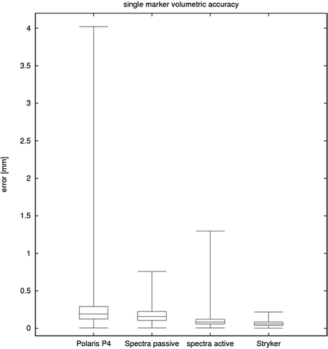
The two active localizer systems, the Stryker Navigation System II camera and the Polaris Spectra (active mode), showed the best results, with trueness values (mean ± standard deviation) of 0.058 ± 0.033 mm and 0.089 ± 0.061 mm, respectively. The Polaris Spectra (passive mode) showed a trueness of 0.170 ± 0.090 mm, and the Polaris P4 showed the lowest trueness at 0.272 ± 0.394 mm with a higher number of outliers than for the other cameras.
The simulation of the different tool configurations in a typical clinical setup revealed that the tracking error can be estimated to be 1.02 mm for the Polaris P4, 0.64 mm for the Polaris Spectra in passive mode, 0.33 mm for the Polaris Spectra in active mode, and 0.22 mm for the Stryker Navigation System II camera.
Introduction
Most current computer aided surgery systems are based on localizer technologies. The technology for determination of the position and orientation of surgical tools with respect to the patient's reference coordinate system is a key component that is used for tool navigation, registration, acquisition of anatomical landmarks, and many others tasks.
Several different tracking technologies are available, of which optical tracking has become established as the state of the art, especially in orthopaedic and neurosurgical navigation systems. Optical tracking systems have proven to be sufficiently reliable and accurate for many clinical applications; they can readily be integrated into the clinical workflow; and they are obtainable at acceptable costs.
The term “accuracy” is often used to describe tracking technologies; however, its application and definition may be inconsistent. It is first necessary to distinguish between the application accuracy and the intrinsic localizer system accuracy. The latter only accounts for a part of the application accuracy, since other errors (tool geometry, registration, image acquisition, etc.) also play an important role. Furthermore, many theoretical inaccuracies have little or no impact on the actual application. For example, errors in the outer portions of the measurement volume may be tolerated if the application only requires a small working volume and the relative position error is small enough. Since almost all applications use dynamic reference bases (DRBs) to track different tools relative to one another, a drift in absolute marker position is acceptable as long as the relative positions are correct.
A definition of accuracy is given in the published standard ISO 5725-1 Citation[1]. Accuracy is defined as the combination of trueness and precision. Trueness is the difference between the measured value and the true position; it is usually represented by the mean value of repeated measurements and generally refers to a systematic error. Precision is a measure of the repeatability; it is usually represented by the standard deviation of repeated measurements and refers to random error and noise.
Apart from these standardized definitions, there are a couple of other measures that are useful. The often-used root mean square distance error (RMS) is given bywith ei being the 3D distance error of measurement i and N the number of measurements. The RMS contains both trueness and precision, and is often misunderstood as a kind of maximum error.
The German engineering guideline for optical 3D measuring systems VDI/VDE 2634 defines a Length Measurement Error (LME) as the difference between a measured length lm and a true or calibrated length lc: LME = lm−lc Citation[3].
Fitzpatrick, West et al. have defined a series of measures for optically tracked tools Citation[4–6]. The Fiducial Localization Error (FLE) is the distance between a measured position and the true position of a single marker (fiducial). This value can be determined for single markers, whereas the Fiducial Registration Error (FRE) and the Target Registration Error (TRE) describe the accuracy of a tool with several markers. The FRE is the positioning error of the single markers of a tool after registration. The TRE is the positioning error of any point of a tool that is not a marker, most commonly the tool tip. The TRE is also applicable for a patient tracker, where the point of interest is normally located far from any marker.
The accuracy information supplied by manufacturers is normally not comparable, since different measures are used as well as different measurement protocols to acquire these measures Citation[2]. For a comparison of different systems it is therefore necessary to define a common measurement protocol.
The topic of optical localizer accuracy has been discussed by several research groups. Chassat et al. Citation[7], Citation[8] described an experimental setup used for the evaluation of four optical tracking systems, among them the Polaris P4 in active and passive modes. For tools, they found an RMS value of 0.189 mm (active) and 0.143 mm (passive) for static tests and maximum errors of 1.062 mm and 0.624 mm, respectively. Khadem et al. Citation[9] assessed a Polaris P4 and a FlashPoint 580 (Image Guided Technology, Inc., Boulder, CO) and found precision of 0.051 mm for the FlashPoint, 0.058 mm for the active Polaris and 0.115 mm for the passive Polaris. A comparison of passive Polaris P4 with the MicronTracker2 (Claron Technology, Inc., Toronto, Ontario, Canada) was recently conducted by Maier-Hain et al. Citation[10], with the Polaris P4 being found to show robust tracking, whereas the MicronTracker was highly sensitive to tracking conditions and less accurate. Wiles et al. evaluated the accuracy of the Polaris P4 and revealed an RMS error of 0.255 mm, with several outliers ranging up to 2.435 mm Citation[2]. In clinical applications further errors, such as those caused by image accuracy or registration, must be added and may lead to unacceptable inaccuracies.
In recent years, new generations of optical camera systems have been developed which promise to be more accurate. This study assesses the accuracy of three localizer systems: the Northern Digital Inc. (NDI) Polaris P4, which is the most prominent camera on the surgical market; its successor, the NDI Polaris Spectra (passive mode), which seems likely to replace it rapidly; the NDI Polaris Spectra (active mode), which has not yet appeared in any commercially available clinical applications; and the Stryker Navigation System II camera.
Materials and methods
Localizers
The Polaris P4 (Northern Digital Inc., Waterloo, Ontario, Canada) is currently the most-used optical tracking system in clinical applications and research. The hybrid version can track both active and passive markers, though in this study only passive tracking was evaluated for the Polaris P4. Passive tools are equipped with at least two infrared-reflecting spheres. The geometric information of the tools is stored in a ROM file.
The Polaris Spectra is the successor to the Polaris P4. The hybrid version used in this study measures the 3D positions of active as well as passive tools. Passive tools are equipped with infrared-reflecting spheres. Active tools are equipped with infrared-emitting diodes (IREDs: 930 nm or 880 nm wavelength) supplied by a battery or a wire connected to an interface box. Passive and wired active tools were used in this study.
The Stryker Navigation System II camera (Stryker, Freiburg, Germany) is an active optical tracking system. The wireless tools are equipped with IREDs and use a sterile battery as the energy supply. The tools and camera communicate bidirectionally for initialization using infrared communication.
Different experiments were defined to assess the accuracy of the three localizers. First, single marker-based measurements were conducted to evaluate the intrinsic accuracy of the positioning systems excluding the influence of tool design. The evaluation was then extended to complete tools incorporating multiple markers. As tool-based evaluation depends strongly on the tool geometry employed, the accuracy of different marker configurations was estimated by simulation based on the measured single-marker accuracy.
Single marker-based evaluation
Single marker-based experiments included static measurements, volumetric measurements and length measurement error (LME) evaluation.
Single marker static accuracy
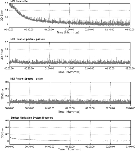
For the static measurements, two single markers were placed in the center of the specified working volume, facing the camera, at a distance of approximately 40 cm from one another. The position of the markers was tracked for three hours, during which environmental conditions (temperature, lighting, etc.) were kept constant and/or were recorded to exclude external influences. The measurements commenced immediately after switching on the cameras. The major objective of this part of the study was to assess the warm-up behavior of the tracking systems. The measured position of marker 1 was evaluated with respect to marker 2. The mean value during the last 30 min of the three-hour measurement period was chosen as the reference level, and the deviation from this reference was determined in three axes (x, y and z) and as a 3D error . The warm-up time was defined as the time after which no values differ by more than 0.1 mm from the reference level.
Single marker volumetric accuracy
A volumetric measurement protocol was used to reveal the performance of the tracking systems throughout a greater volume and depending on the position in the measurement volume. A Coordinate Measurement Machine (CMM) was used for the volumetric measurements. The Zeiss Prismo 10 CMM has a measurement volume of approximately 1000 mm × 1600 mm × 2400 mm and an uncertainty of measurement of u = 5.0 + L/220 µm (where L is the length in mm).
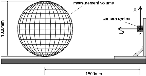
For the evaluation, a spherical volume with a diameter of 1000 mm and a center located approximately 1600 mm from the camera was chosen (see ), yielding a maximum theoretical measurement uncertainty for the CMM of 9.54 µm. The appropriate marker was fixed to the tool tip of the CMM, which accessed to 900 grid positions on a regular grid with 100-mm spacing.
The camera was mounted on the CMM such that the center of the camera's measurement volume corresponded with the central grid position. The position of the marker was continuously recorded every 33 ms, giving 30 measurements per second. The CMM stopped at each grid position for three seconds. From the complete data set, the positioning data of the 900 static grid points was selected and then reduced to those positions within the intersection of the specified measurement volumes of the different camera systems. A point-to-point registration was used to align all measurements to the CMM coordinate system. At each position, the 30 measurement values from the middle of a measurement interval were selected to avoid errors resulting from machine vibration or oscillation. For each position, the trueness and precision were calculated, as well as the mean trueness and precision for the whole volume, an RMS error, and the 95% and 99% confidence intervals.
Single marker length measurement error
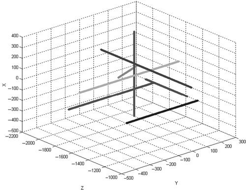
The German engineering guideline VDI/VDE 2634 Citation[3] describes the accuracy assessment for optical length measurement systems. The measure used in the guideline is the Length Measurement Error (LME; see above), which is determined using an accurately manufactured and calibrated artifact with known marker distances. On the basis of this guideline, the LME was determined using the previously acquired volumetric measurements for reference instead of an artifact, as the CMM positioning accuracy meets the manufacturing accuracy requirement of the guideline. Seven measurement lines and five test lengths on each line were defined (see ). For each length, the LME was calculated as the difference between the real and desired value, i.e., LME = |lmeasured − lnominal|. The mean and standard deviation of the LME were calculated, and the single measurement errors were evaluated as a diagram.
Tool-based evaluation
Since clinical applications generally use tools incorporating several markers instead of only a single marker, the experiments were extended to tool-based measurements.
Tool-based volumetric evaluation
Volumetric tool measurements were performed using the CMM in a setup similar to those for the single markers. For the passive Polaris P4 and Polaris Spectra, a tool conforming to the tool design guidelines with four passive spheres was used. For the active Polaris Spectra an original tool from NDI having four IREDs in a single plane was used, and for the Stryker camera a tool by Stryker with five IREDs was used. The tools were fixed to the CMM tool tip and the machine approached the same 900 equally spaced grid positions as in the single marker measurements. The position and orientation were recorded and the data set was reduced to 30 values per grid position and the intersection of the specified measurement volumes. After a point-to-point registration of all recorded positions, the 3D positioning error was determined (trueness and precision), and the mean and standard deviation for the whole volume, as well as an RMS error, were calculated.
Estimation of clinical accuracy
For clinical applications, the accuracy of the tools employed is of great interest. This clinical accuracy is influenced by the configuration of the tracked tools, e.g., tool geometry, marker distribution, number of markers and relative position of tools to one another.
The target registration error (TRE) describes the error at a given position r which may be caused by inaccurately determined marker (fiducial) positions. Assuming an isotropic error distribution of the fiducial localization error (FLE), the TRE is given bywith N being the number of markers, dk the distance of r from the kth principle axis, and fk the RMS distance of the fiducials from the kth axis.
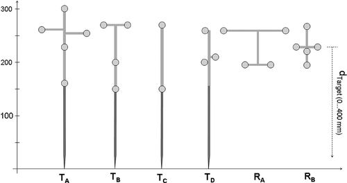
In a clinical context, a surgical tool or pointer is usually tracked relative to a reference frame so that both tools have an impact on accuracy. The TRE of a configuration for measuring two tools can be estimated a follows Citation[6]:To estimate clinical accuracy, several commonly used tool configurations (four different tools and two different reference frames) were defined with different marker configurations ranging from large tools with five markers to small tools with two markers (see ).
For each localizer system, every combination of tool and reference was simulated. The target point r was set fixed to the tool tip (see ), whereas the distance from the target point r to the reference frame was varied from 1 to 400 mm, simulating a typical workspace in computer assisted navigation systems.
Results
Static evaluations revealed that only the Polaris P4 shows significant warm-up behavior, which is observed for up to 42 min after it is switched on. The Polaris Spectra (in both active and passive modes) performed best with respect to warm-up time, showing almost no effect (see ). The Stryker camera showed a slight drift, but with a small amplitude below 0.1 mm within the first 60 minutes. Although the Polaris Spectra systems showed almost no warm-up effect, the maximum 3D error for Spectra was bigger than for the Stryker camera, which performed best. Detailed results of the static measurements are given in .
Table I. Results of the relative static measurements. Warm-up time was defined as the time after which no value differed by more than 0.1 mm from the mean value for the final 30 min of the measurement period.
The volumetric measurements with single markers showed position errors ranging from 0.058 ± 0.033 mm (mean ± standard deviation) to 0.272 ± 0.394 mm and a precision ranging from 0.002 mm for the Stryker camera to 0.042 mm for the Polaris P4 (see ). Both Polaris cameras showed several outliers. Some positions in the outer regions of the measurement volume show considerably higher values for trueness and precision (see and ).
Figure 5. Volumetric single marker measurements: volumetric distribution of trueness throughout the measurement volume.
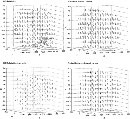
Table II. Results of the volumetric single marker measurement.
The LME was determined as described above. The Stryker and active Polaris Spectra produced low LME values of 0.051 mm and 0.067 mm, respectively. The Polaris P4 suffers from said outliers, resulting in the highest LMEmax of all the cameras. These results are presented in and .
Figure 7. Length Measurement Error: LME diagram (upper portion of each quarter) and histogram of LMEs.
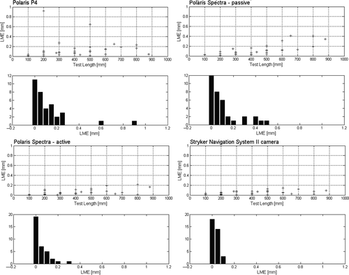
Table III. Results of the Length Measurement Error evaluation.
The second part of the evaluation included the volumetric assessment of tools in translation and orientation. The results of these volumetric tool measurements were similar to the single marker measurements. The values for trueness and precision were lower than for the single marker measurements for all but the Stryker camera, for which the values were slightly higher. All results are presented in and . shows the results of the rotational evaluation. The angular deviation is far below 1° in the 95% confidence interval for all systems, but again the Polaris P4 suffers from a high number of outliers, causing a 99% CI of 2.181° and a maximum deviation of 3.4°
Figure 8. Volumetric tool measurements: volumetric distribution of trueness throughout the measurement volume.
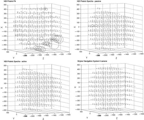
Table IV. Results of the volumetric tool measurements: translation.
Table V. Results of the volumetric tool measurements: rotation.
As expected, the estimation of clinical accuracy revealed that the possible error is quite different for the tool configurations used and is strongly dependent on the distance of the tool tip from the reference frame (see ). In the worst-case scenario using tool TD at a distance of 400 mm from RB, the maximum error was 1.83 mm for the Polaris P4, 1.14 mm for the passive Polaris Spectra, 0.60 mm for the active Polaris Spectra, and 0.39 mm for the Stryker Navigation System II camera. Using marker configuration TA at a distance of 400 mm from RA led to an error of 1.02 mm for the Polaris P4, 0.64 mm for the passive Polaris Spectra, 0.33 mm for the active Polaris Spectra, and 0.22 mm for the Stryker Navigation System II camera.
Discussion
The experiments conducted in this evaluation showed good accuracies for the optical tracking systems used, but also revealed clear differences between them. Comparisons with the values reported in references Citation[7] and Citation[8], as well as the measurements for the Polaris P4, show a clear improvement with the newer generations of localizers (Polaris Spectra and Stryker camera). The warm-up process for the newer systems is only short, based on relative positioning between a tool and a reference base. The Polaris Spectra seems to solve the problem of its predecessor in this respect by reducing the warm-up time to almost zero. The Stryker camera shows a slight drift over a long period of time, but the effect is negligible (<0.1 mm) after a few minutes for all systems except the Polaris P4.
The volumetric measurements showed a clear dependency between the measurement accuracy and the position within the volume. Positions in the center of the volume could generally be located with higher accuracy, and almost all of the outliers were in the outer regions of the volume (see and ). The two active localizer systems, the Stryker Navigation System II camera and the NDI Polaris Spectra (active mode), showed the best results for reliability and accuracy, with the Stryker camera having the lowest number of outliers. All NDI systems showed higher noise and thus lower precision than the Stryker camera. The precision differs in the three spatial directions, usually being lower in the z-direction as would be expected. This effect could be observed in all experiments.
In comparing active and passive tracking with the Polaris Spectra, our study clearly shows better results for the active mode. This is in accordance with the results reported by Khadem et al. Citation[9], showing higher precision for active Polaris P4 compared to the passive mode. However, it should be noted that Chassat and Lavallée determined lower errors for the passive P4 Citation[7].
For clinical applications, the performance of tools is more important than that of single markers. The accuracy in determining a tool's position can be improved by using redundant information from several markers and appropriate algorithms. Tools with at least three markers can also be tracked with six degrees of freedom, providing additional information on the rotation of the tool. However, the tool design plays an important role in the accuracy of the tool, particularly for the rotation. The measurements performed in this study can only serve as examples; other tool configurations could yield different results. The tools evaluated were either standard tools obtained from the respective manufacturer (the active tools for the Stryker and Polaris Spectra) or specially constructed according to the manufacturer's specifications (the passive tools for the Polaris P4 and Polaris Spectra). The results of the volumetric measurements with tools were similar to those for the single marker experiment. Again, the Stryker camera produced the best results in translation and rotation, and the Polaris P4 was the most inaccurate system.
Evaluating the rotational measurements, the results were satisfactory for the given tools and orientation, with only the P4 result being slightly above 0.5° for the 95% confidence interval.
The rotational error is of high importance, since the instrument (tip) positioning error produced by inaccurate orientation measurements can easily be larger than any translational error measured in this study. The simulation of target registration error for different tool configurations demonstrates its high impact. shows that the tool geometry affects the minimal error, whereas the reference frame influences the gradient of the error depending on the tool length. As these values are just simulations, the absolute values should only be used to compare the evaluated camera systems with different tool configurations.
Conclusion
Three optical tracking systems for computer aided surgery applications were evaluated. The new generations of optical localizer systems showed smaller position errors and almost no warm-up effect as compared to the NDI Polaris P4, and therefore seem to meet the accuracy requirements of many clinical applications.
The two active localizer systems, the Stryker Navigation System II camera and the NDI Polaris Spectra (active mode), showed the best results for reliability and accuracy; however, at present, no commercially available navigation system using the active Polaris Spectra is known. The Stryker camera had the highest overall accuracy, while the Polaris P4 system demonstrated significantly lower accuracy and a higher number of outliers.
The comparison of active and passive tracking with the Polaris Spectra revealed better accuracy with the active tracking mode; in the passive mode, the localization error was almost twice as high.
Acknowledgment
This study was supported in part by Stryker Leibinger, Freiburg, Germany.
References
- ISO 5725-1: Accuracy (trueness and precision) of measurement methods and results. Part 1: General principles and definitions. International Standards Organization, 1994.
- Wiles AD, Thompson DG, Frantz DD. Accuracy assessment and interpretation for optical tracking systems. In: Proceedings of SPIE Medical Imaging 2004: Visualization, Image-Guided Procedures and Display, San Diego, CA, February 2004. Proceedings of SPIE 2004;5367:421–432.
- VDI/VDE Guideline 2634: Optical 3D measuring systems–Imaging systems with point-by-point probing. VDI/VDE, 2002.
- Fitzpatrick JM, West JB. The distribution of target registration error in rigid-body point-based registration. IEEE Trans Med Imaging 2001; 20(9)917–927
- West JB, Fitzpatrick JM, Toms SA, Maurer CR, Maciunas RJ. Fiducial point placement and the accuracy of point-based, rigid body registration. Neurosurgery 2001; 48(4)810–816, discussion 816–817
- West JB, Maurer CR. Designing optically tracked instruments for image-guided surgery. IEEE Trans Med Imaging 2004; 23(5)533–545
- Chassat F, Lavallée S. Experimental protocol of accuracy evaluation of 6-D localizers for computer-integrated surgery: Application to four optical localizers. In: Wells WM, Colchester A, Delp S, editors. Proceedings of the First International Conference on Medical Image Computing and Computer-Assisted Intervention (MICCAI ’98), Cambridge, MA, October 1998. Lecture Notes in Computer Science 1496. Berlin: Springer; 1998. 277–284.
- Schmerber S, Chassat F. Accuracy evaluation of a CAS system: laboratory protocol and results with 6D localizers, and clinical experiences in otorhinolaryngology. Comput Aided Surg 2001; 6(1)1–13
- Khadem R, Yeh CC, Sadeghi-Tehrani M, Bax MR, Johnson JA, Welch JN, Wilkinson EP, Shahidi R. Comparative tracking error analysis of five different optical tracking systems. Comput Aided Surg 2000; 5(2)98–107
- Maier-Hein L, Franz A, Meinzer HP, Wolf I. Comparative assessment of optical tracking systems for soft tissue navigation with fiducial needles. In: Proceedings of SPIE Medical Imaging 2008: Visualization, Image-Guided Procedures, and Modeling, San Diego, CA, February 2008. Proceedings of SPIE 2008;6918:691870.
