Abstract
Computer Assisted Orthopaedic Surgery (CAOS) technology is constantly evolving with support from a growing number of clinical trials. In contrast, reports of technical accuracy are scarce, with there being no recognized guidelines for independent measurement of the basic static performance of computer assisted systems. To address this problem, a group of surgeons, academics and manufacturers involved in the field of CAOS collaborated with the American Society for Testing and Materials (ASTM) International and drafted a set of standards for measuring and reporting the technical performance of such systems. The aims of this study were to use these proposed guidelines in assessing the positional accuracy of both a commercially available and a novel tracking system.
A standardized measurement object model based on the ASTM guidelines was designed and manufactured to provide an array of points in space. Both the Polaris camera with associated active infrared trackers and a novel system that used a small visible-light camera (MicronTracker) were evaluated by measuring distances and single point repeatability. For single point registration the measurements were obtained both manually and with the pointer rigidly clamped to eliminate human movement artifact.
The novel system produced unacceptably large distance errors and was not evaluated beyond this stage. The commercial system was precise and its accuracy was well within the expected range. However, when the pointer was held manually, particularly by a novice user, the results were significantly less precise by a factor of almost ten.
The ASTM guidelines offer a simple, standardized method for measuring positional accuracy and could be used to enable independent testing of tracking systems. The novel system demonstrated a high level of inaccuracy that made it inappropriate for clinical testing. The commercially available tracking system performed well within expected limits under optimal conditions, but revealed a surprising loss of accuracy when movement artifacts were introduced. Technical validation of systems may give the user community more confidence in CAOS systems as well as highlighting potential sources of point registration error.
Introduction
Computer Assisted Orthopaedic Surgery (CAOS) systems are now well established in several areas of orthopaedic surgery, and their popularity continues to increase worldwide. CAOS technology is constantly evolving along with an expanding list of potential surgical indications Citation[1]. The increasing use of computer systems, particularly in knee arthroplasty, has been supported by randomized clinical trials that demonstrate a more consistent final position of implanted devices compared with that achieved with conventional instrumentation techniques Citation[2–5]. In these trials, the comparison of navigated data to hip-knee-ankle radiographs or computed tomography (CT) scans represents a form of clinical validation Citation[6] that uses the orientation of the components to measure accuracy and hence validate systems. At present, most of the available data supporting CAOS systems relates to the clinically measured positional accuracy of an implanted device as compared with the planned or ideal position. Unfortunately, there are many potential sources of error in the entire surgical process that may lead to sub-optimal clinical performance of a computer system. These include surgeon errors when collecting anatomical and kinematics data Citation[7], Citation[8], tracking inaccuracies, particularly inadvertent intra-operative tracker movement Citation[9], and errors associated with post-operative radiological measurements of implant position Citation[10], Citation[11].
In comparison to clinical validation, technical accuracy relates to the performance of the overall system or its individual components (subsystems) without the introduction of these unquantified variations or errors. For optical tracking systems, for example, one of the most basic functions is the accurate three-dimensional (3D) location of a point in space. Unfortunately, there are no published guidelines for reporting accuracy, and the only technical information available is that provided by the manufacturers. This makes it difficult to know the relative contribution of each source of error to the final outcome, which is an important consideration when adapting CAOS technology to new areas of orthopaedics. Having only clinical data available to guide potential users limits direct comparisons between complete systems or subsystems.
To address this problem, a group of surgeons, academics and product manufacturers involved in the use and development of CAOS systems met with members of the American Society for Testing and Materials (ASTM) International, one of the largest standards-developing organizations in the world. They drafted a set of standards for measuring and reporting the basic static performance of computer aided surgical systems under defined conditions Citation[12]. The aims of the present study were to use these guidelines to design and manufacture a standardized measurement object (phantom) and to assess the positional accuracy of both a commercially available infrared (IR) tracking system and a novel optical tracking system that used a small visible-light camera.
Materials and methods
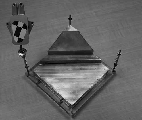
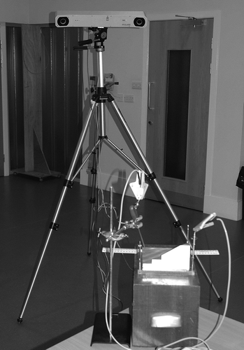
The proposed ASTM International standard was obtained and its recommendations used to design a phantom model. This consisted of a 150 × 150 × 20 mm base plate and two additional levels including a single 30° slope. The final model was machined from a billet of marine-grade aluminum alloy 6082-T6, chosen for its dimensional stability, using a vertical computer numerical controlled (CNC) milling machine This created a surface on which an array of holes were drilled at known locations in the 3D space. The holes, with chamfers of Ø 1.0 mm, were designed to accommodate a ball-nosed pointer tip of a known diameter, thus allowing the tip to fit into the hole and remain at the same position in space at all orientations of the pointer. A Perspex base unit with three different sites for rigid tracker attachment was made to hold the phantom. This avoided the need to directly modify it, which could have potentially resulted in the loss of its structural accuracy, and also allowed different metal pins (secured in position by grub screws) and corresponding trackers to be attached, permitting the evaluation and comparison of different systems (). As a consequence of this modularity, we did not know the precise location of the points on the phantom relative to the origin of the attached rigid body. We therefore chose to evaluate the accuracy of distance measurements and single point repeatability for two different systems. The first system was the Polaris camera (Northern Digital Inc., Waterloo, Ontario, Canada) in association with active IR trackers from the Orthopilot® navigation system (B. Braun Aesculap, Tuttlingen, Germany). The second evaluation was of a fully passive visible-light video camera (MicronTracker, Claron Technology Inc., Toronto, Ontario, Canada), with corresponding trackers marked with a visible geometric pattern, that was to be used in the development of a novel system. A potential advantage of this camera was its small size (the case dimensions are 172 × 57 × 57 mm) and consequent portability, making it useful in a clinical setting where space can be limited. For each system, Orthopilot® software was appropriately modified to allow repeated single point measurements. The phantom was positioned within the optimum working range for each camera and in the center of the measurement volume. The fixed tracker generated an orthogonal xyz coordinate system: seen from the camera, x was horizontal, y depth (i.e., distance away from the camera) and z vertical.
For distance measurements, two users independently collected the same 10 points in sequence, which provided nine measurements between 50 and 130 mm. The pointer was held with one hand and a foot pedal used to register each point in a similar manner to that employed intra-operatively. This procedure was repeated three times to give a total of 54 measurements for each user.
Single point repeatability was evaluated by using the pointer to register the same point 20 times in succession without removing it from the hole. Between trials, the pointer was removed and then repositioned in the hole. Three observers performed the repeatability measurements on two occasions using one- and two-handed pointer grips with the aim of holding the pointer as still as possible. To eliminate potential human movement artifacts, a further five sets of measurements were obtained with the pointer held rigidly in a clamp (). Each trial generated 20 points, and a best-fit sphere was determined for the minimum size required to encompass all of the points. The sphere diameter was used to represent the maximum 3D error for registration of the same point.
Results
Distance measurements
The distances between points as measured by the tracking systems were calculated and compared to the known absolute distances (). For these linear distance measurements, the Polaris camera from the commercial system had a mean error of 0.4 mm with an overall range of error of 2.3 mm (−0.8 to 1.5 mm). In comparison, the novel system incorporating the visible-light camera was found to be unstable with errors of up to 6 mm. As a consequence of this unacceptable level of inaccuracy, the second stage in the evaluation process was not undertaken with this camera.
Table I. Distance measurement errors for both commercial and novel tracking systems.
Single point repeatability
Observers 1 and 2 (with prior CAOS experience) produced similar results for both single- and two-handed pointer grips, with sphere diameters of approximately 2.5 mm being required to encompass all the points (). Measurements obtained by observer 3 (a novice with no prior navigation experience) showed inconsistencies, and attempts to improve pointer stability with two hands led to an unexpected increase in the best-fit sphere diameter from 1.4 to 4.1 mm.
Table II. Minimum sphere diameters required to contain points in space for observer (single- and two-handed grips) and clamped trials.
By comparison, the results obtained with the pointer clamped were considerably more precise and were contained within spheres of 0.2–0.3 mm diameter. However, when the pointer was removed and re-clamped, the center of the best-fit sphere for each trial varied in its location. This resulted in the cumulative error of the five clamp trials being significantly higher than the error for each separate trial, with a sphere of almost 2 mm diameter being required to encompass all 100 points.
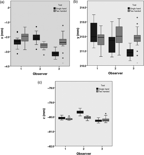
The x, y and z coordinates for each point were examined separately and the spread of values represented as box plots (). These illustrated the intra- and inter-observer variation within and between each trial, respectively. In particular, they demonstrated the relative contributions of each axis to the overall 3D error. The z-axis, which represented the vertical axis relative to the tracker, had the least amount of overall variation, whereas the largest spread of values was seen with the y-axis, representing the distance from the camera.
Discussion
Subsystem testing of different components of a CAOS system can characterize their relative contribution to the overall system as a whole. In this case we mainly assessed the camera, which is a significant factor in accurate point registration and a fundamental requirement of a computer assisted surgical tracking system. The guidelines proposed by ASTM International Citation[12] offered a simple, standardized method of measuring positional accuracy, and we have shown that these guidelines can be used to enable independent accuracy testing. To our knowledge, there are no plans to publish the standards or make the draft document readily available for the potential benefit of other CAOS researchers. The authors will, however, be happy to provide a copy of the draft document to interested parties.
For a novel tracking system in development we demonstrated an unacceptable level of positional accuracy at an early stage, preventing any clinical evaluation from being undertaken until the basic static performance was addressed. This showed the usefulness of conducting a very basic assessment, as this resulted in the saving of time, money and patient inconvenience; if the novel CAOS system had been assessed as a whole, identifying sources of error would have been more difficult. This approach has also enabled the continued development of the other aspects of the novel system by the substitution of a standard IR tracking system for the visible-light system; this would not have been possible without being able to identify the tracking system as the source of error. The inclusion of a small visible-light camera in the novel system is currently being re-addressed.
We were also able to validate the point location accuracy of a commercially available tracking system. With the pointer clamped, the precision was well within the expected range of 1 mm for each trial. However, clamp re-application resulted in significantly less overall precision for the five trials, with variation of the sphere centers and a larger cumulative error. This loss of precision may be due to small variations in relative pointer orientation between trials.
Human movement artifacts introduced a surprising loss of accuracy by a factor of almost ten. This was in spite of optimal test conditions and attempts to hold the pointer as still as possible. Operator experience may also contribute to accuracy of point registration; less consistent results were obtained by a novice operator in our study who produced both the largest and smallest sphere diameters. By comparison, the experienced operators produced more consistent results that were similar to those from the combined clamp trials, but were still significantly less precise than the individual clamped measurements.
For the end-user of a CAOS system, clinical outcome measures such as post-operative limb alignment and implant positioning may be more relevant than reports on technical accuracy. However, the degree of point registration accuracy required for different surgical steps may be an important consideration, as small errors in locating landmarks can lead to significant errors for anatomical reference frames. For example, in total knee arthroplasty, a 7-mm anteroposterior error in identifying one of the femoral epicondyles can correspond to approximately 5° of rotational error in the transverse plane Citation[1]. Potential errors such as this, along with inconsistent anatomical landmark identification Citation[7], may help to explain why some studies have failed to demonstrate any advantage of CAOS systems over traditional instrumentation techniques Citation[13], Citation[14].
Comprehensive, standardized testing and reporting of technical as well as clinical accuracy should increase confidence amongst the user community that these systems will achieve their stated outcome goals.
Acknowledgments
The authors would like to thank Andrew Mor, who supplied the draft ASTM standard, John Gillan and the Physics Department workshop at the University of Strathclyde, and Davie Robb from the Bioengineering Unit. They would also like to thank B. Braun Aesculap for the provision of the Polaris camera and software.
References
- Siston RA, Giori NJ, Goodman SB, Delp SL. Surgical navigation for total knee arthroplasty: A perspective. J Biomech. 2007; 40: 728–735
- Bäthis H, Perlick L, Tingart M, Lüring C, Zurakowski D, Grifka J. Alignment in total knee arthroplasty: A comparison of computer-assisted surgery with the conventional technique. J Bone Joint Surg (Br) 2004; 86-B: 682–687
- Chauhan SK, Scott RG, Breidahl W, Beaver RJ. Computer-assisted knee arthroplasty versus a conventional jig-based technique: A randomized, prospective trial. J Bone Joint Surg (Br) 2004; 86-B: 372–377
- Sparmann M, Wolke B, Czupalla H, Banzer D, Zink A. Positioning of total knee arthroplasty with and without navigation support: A prospective, randomized study. J Bone Joint Surg (Br) 2003; 85-B: 830–835
- Matziolis G, Krocker D, Weiss U, Tohtz S, Perka C. A prospective, randomized study of computer-assisted and conventional total knee arthroplasty. Three-dimensional evaluation of implant alignment and rotation. J Bone Joint Surg (Am) 2007; 89-A: 236–243
- DiGioia AM, Mor AB, Jaramaz B, Bach JM. Accuracy and validation for surgical navigation systems. AAOS Bulletin 2005; 53(5)
- Robinson M, Eckhoff DG, Reinig KD, Bagur MM, Bach JM. Variability of landmark identification in total knee arthroplasty. Clin Orthop Relat Res 2006; 442: 57–62
- Spencer JMF, Day RE, Sloan KE, Beaver RJ. Computer navigation of the acetabular component: A cadaver reliability study. J Bone Joint Surg (Br) 2006; 88-B: 972–975
- Mayr E, Moctezuma de la Barrera J-L, Eller G, Bach C, Nogler M. The effect of fixation and location on the stability of the markers in navigated total hip arthroplasty: A cadaver study. J Bone Joint Surg (Br) 2006; 88-B: 168–172
- Kalteis T, Handel M, Herold T, Perlick L, Paetzel C, Grifka J. Position of the acetabular cup–accuracy of radiographic calculation compared to CT-based measurement. Eur J Radiol 2006; 58: 294–300
- Siu D, Cooke TD, Broekhoven LD, Lam M, Fisher B, Saunders G, Challis TW. A standardized technique for lower limb radiography. Practice, applications, and error analysis. Invest Radiol 1991; 26(1)71–77
- International. ASTM. Standard Practice for Measurement of Positional Accuracy of Computer Assisted Surgical Systems, February 2007 draft
- Spencer JM, Chauhan SK, Sloan K, Taylor A, Beaver RJ. Computer navigation versus conventional total knee replacement: No difference in functional results at two years. J Bone Joint Surg (Br) 2007; 89-B: 477–480
- Lützner J, Krummenauer F, Wolf C, Günther K-P, Kirschner S. Computer-assisted and conventional total knee replacement: A comparative, prospective, randomised study with radiological and CT evaluation. J Bone Joint Surg (Br) 2008; 90-B: 1039–1044


