Abstract
Modern Computer Aided Design/Modeling (CAD/CAM) software allows complex surgical simulations, but it is often difficult to transfer and execute precisely the planned scenarios during actual operations. We describe a new method of integrating CAD/CAM surgical plans directly into a computer surgical navigation system, and demonstrate its use to guide three complex orthopaedic surgical procedures: a periacetabular osteotomy of a dysplastic hip, a corrective osteotomy of a post-traumatic tibial deformity, and a multi-planar resection of a distal femoral tumor followed by reconstruction with a CAD custom prosthesis.
Introduction
The analysis of a deformity and its subsequent correction are integral to many common orthopaedic surgical procedures. These analyses and the associated preoperative surgical planning are often performed using standard two-dimensional (2D) radiographs, with reference to normal and standard measurement parameters Citation[1–3]. Advanced Computer Aided Design/Modeling (CAD/CAM) software has been used for surgical planning, facial deformity correction, and oral implant placement in cranio-maxillofacial surgical procedures Citation[5–8]. The technique enables surgeons to import 2D CT data and to generate a precise three-dimensional (3D) virtual representation of the bones. A range of possible surgical plans, such as potential locations of osteotomies, and options for realignment of bones and positioning of implants, can be simulated on the virtual skeleton prior to the real operation. Bone tumor surgery using a similar approach has been reported, with tumor resection and subsequent custom prosthetic reconstruction being accomplished as a one-step procedure Citation[9], Citation[10]. However, even if a perfect operation can be simulated preoperatively using CAD/CAM software, it is difficult to transfer and execute precisely the planned scenarios during the actual operation.
In this paper, we describe a new method of integrating CAD/CAM surgical plans into a computer assisted surgical navigation system and demonstrate its use to guide three complex orthopaedic surgical procedures: a periacetabular osteotomy of a dysplastic hip, a corrective osteotomy of a post-traumatic tibial deformity, and a multi-planar resection of a distal femoral tumor followed by reconstruction with a CAD custom prosthesis.
Methods
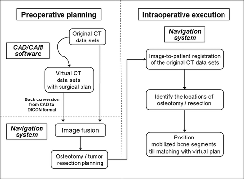
For each of the three patients, preoperative thin-slice (0.625 or 1.25 mm) axial CT images of the region to be operated on were acquired using a 16–detector scanner (General Electric LightSpeed, Milwaukee, WI). These data were recorded in a generic DICOM format and subsequently imported into MIMICS® (Materialise's Interactive Medical Image Control System, Materialise, Ann Arbor, MI), a CAD/CAM software that converts DICOM data into a proprietary format. Two-dimensional axial images, reformatted images (coronal and sagittal) and 3D bone models were reconstructed, and preoperative virtual simulations of the osteotomies, deformity correction, tumor resection and prosthetic reconstruction were performed. The surgical plans in MIMICS format were then back-converted to CT data sets in DICOM format, and both the original CT data sets and the virtual surgical planning CT data sets were transferred to a cranial navigation software (Stryker iNtellect Cranial Navigation Software, version 1.1, Stryker Navigation, Freiberg, Germany) for image fusion. The data sets of the fused images were then imported back into a CT-based navigation system (Stryker CT Spine Navigation, version 1.6, Stryker Navigation, Freiberg, Germany) for osteotomy or resection planning. The navigation system was toggled to display the CT data sets with the virtual surgical plans. Virtual markers (virtual pedicle screws in the CT Spine Navigation software) were then placed to mark the plane and orientation of the planned osteotomy or tumor resection.
Intraoperative navigation in bone surgery has been described previously (see, for example, references 9, 10 and 13). In the cases reported here, after performing an appropriate surgical exposure, a tracker was attached to the bone in which the deformity or tumor was located. Image-to-patient registration to match corresponding points on the patient's real intraoperative anatomy and the preoperative original CT images was performed by paired-points and surface matching. The registration process was completed and the navigation was considered accurate only if there was exact real-time matching between the anatomy and the virtual images; this was verified by running the registration probe over the bone surface or by checking specific and well-defined anatomic landmarks. We next located the anatomic position of the virtual markers (pedicle screws) on the involved bones, using navigated tools, and then marked the intended osteotomy/resection sites by diathermy. An oscillating saw and osteotome were used to perform the osteotomy or tumor resection. For the two patients undergoing correction of deformities, the mobile bone segments were grossly realigned using visual cues from the patients’ anatomy. The navigation system was then toggled to display the data sets with the associated virtual surgical plans. By placing the navigation probe on different areas of the mobile bone segments, the final bone positions could be modified and adjusted to match the planned position, after which internal fixation was applied. This new method is summarized in .
Case reports
Patient 1
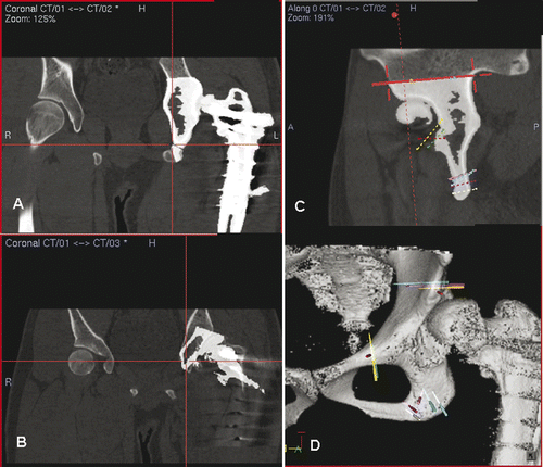
This 21-year-old man had a history of developmental dysplasia of the left hip. The deformity of the proximal femur had been corrected by wedge osteotomy; however, the femoral head was still subluxed because of a dysplastic shallow acetabulum. A corrective triple pelvic osteotomy was planned to improve the femoral head coverage. The image data sets of the preoperative CT scan of the pelvis were imported into the MIMICS software, and the amount of acetabular dysplasia could be identified and quantified from the 3D pelvic bone model generated. Three virtual osteotomies were created () and virtual realignment of acetabulum was performed (). The virtual surgical plans were then converted back into DICOM format and imported into the CT-based navigation system (). The pelvis was exposed using an ilioinguinal approach, and the locations of the planned osteotomies were identified under intraoperative navigation guidance. The osteotomies were accomplished with an oscillating saw and osteotomes, then the mobile acetabulum was rotated in the anterolateral inferior direction until the bone defect created above the supra-acetabular osteotomy or the final position of the acetabulum matched the virtual surgical plans. An iliac crest autograft was then inserted into the bone defect in the supra-acetabular region, and the reconstruction was stabilized with two 6.5-mm cannulated titanium screws under navigational guidance. Postoperative plain radiograph showed satisfactory alignment and union of all osteotomy sites at 4 months after surgery ().
Figure 2. Periacetabular osteotomies (red planes) were planned on a virtual 3D pelvic model generated from the patient's CT data using MIMICS software (A). The acetabular bone segment (blue) was virtually realigned until the measured acetabular angle was adequate or equal to that on the opposite side (B). The resulting bone defect created above the acetabulum (red arrow in B) could be measured and its dimensions used to guide the harvesting of a bone graft from the ipsilateral iliac crest (C). A postoperative plain radiograph (D) showed good fitting of the bone graft and alignment of the acetabulum (dotted line).
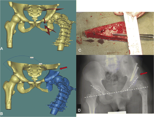
Figure 3. Preoperative display of the surgical planning for Patient 1 on the navigation monitor. Coronal (A) and sagittal (C) images showed image fusion of CT data sets with virtual osteotomies (representing the pelvic model in ) and the original CT data sets. The fusion images helped to locate exactly the planned planes of the osteotomies, which were then marked with virtual screws (C). Coronal images (B) illustrated image fusion of CT data sets with virtual realignment (representing the pelvic model in ) and the original CT data sets. The planes of the periacetabular osteotomies were marked with virtual screws on the reconstructed 3D pelvic model (D). For the actual operation, following surgical exposure of the acetabulum and insertion of a tracker into the iliac crest, image-to-patient registration was performed on the original CT datasets. The osteotomy planes were defined by locating the positions of the virtual screws under navigational guidance. The pelvic bone was then osteotomized with an oscillating saw and osteotomes. The acetabular bone segment was realigned to open a bone defect above the acetabulum, and an iliac crest bone graft () was inserted into this defect. On toggling the fusion image to CT datasets with virtual realignment, the surface of the mobilized acetabular bone segment was traced by a navigation pointer. The position of the acetabulum was adjusted and assessed to be optimal if it matched with its corresponding position on the CT datasets with virtual realignment. The acetabular segment was then temporarily secured to the iliac bone with K-wires. The bone graft was fixed with two 6.5-mm cannulated titanium screws under navigational guidance () which helped to avoid penetration into the hip joint.
Patient 2
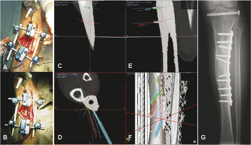
This patient was a 47-year-old man who had fallen from a ladder and sustained a tibial plateau fracture, an open fracture of the left tibial shaft, and a fracture of the left os calcis. He was treated with closed reduction and screw fixation of the tibial plateau fracture, open reduction and internal fixation of the os calcis fracture, and wound debridement and application of an external fixator for the open tibia fracture. The external fixator was removed 3 months after the injury. At 5 months post-injury, all the fractures had healed except the open fracture of the tibial shaft. A preoperative CT scan of the left tibia confirmed non-union with deformity. The CT image data sets were imported into the MIMICS software, and computer aided analysis revealed procurvatum, varus and rotational deformity of the left tibia at the fracture site (). A virtual corrective osteotomy was performed (), and the virtual surgical plans were then converted back to DICOM format and transferred to the CT-based navigation system. Under intraoperative navigational guidance, realignment pins were inserted into the planned locations on the proximal and distal tibial segments and tibial osteotomy was performed ( and ). The mobilized distal bone segment was then realigned until its position matched the virtual plans on the navigation display (). The bone was then temporarily stabilized with an external fixator, after which internal fixation with lateral plating was performed. Plain radiographs showed good alignment of the tibia, and the fracture had healed at 5 months following surgery ().
Figure 4. For Patient 2, a 3D model of the left tibial fracture non-union with deformity was generated from the MIMICS software (A). The plane of the osteotomy (red) was then planned at the fracture line in the reconstructed 3D tibial model (B).
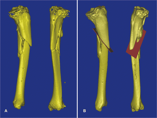
Figure 5. In a virtual simulation of a corrective osteotomy, the proximal and distal segments of the tibia were separated. The distal tibia (yellow) was mobilized from its original deformed position to its corrected position (gray). The final position was determined by assessing the mechanical axis of the two tibial segments, the continuity of the anterior tibial crest, and also the knee and ankle joint lines. The deformity could then be quantified, and was measured as 11° procurvatum (A), 7° varus (B) and 9° rotational deformity (C). To facilitate the deformity correction, parallel alignment pins were planned at the proximal tibia (two red pins) and the distal tibia in the corrected position (two green pins). The distal tibia (gray) and the green alignment pins were moved together and back to the original deformed position. The locations of the distal alignment pins on the deformed distal tibia (two red pins) were defined.
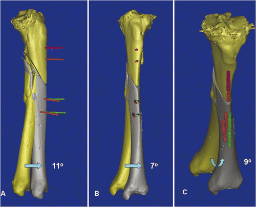
Figure 6. After placing a patient tracker on the proximal tibia and performing image-to-patient registration, proximal and distal alignments pins were inserted into the corresponding tibial segments under navigational guidance (A). The plane of the tibial osteotomy was identified and marked according to the navigation planning, and the osteotomy performed using an oscillating saw. The distal tibial segment was then realigned until the proximal and distal alignment pins were parallel and stabilized with an external fixator (B). A navigation probe was run along the surface of the realigned distal tibia, and the tip of the probe matched with the bone surface of the realigned tibia in the virtual navigation plan in the coronal (C), axial (D) and sagittal (E) images, thereby indirectly navigating and confirming the final corrected position of the distal tibial segment. The reconstructed 3D tibia model (F) was less useful for this validation because the CT Spine Navigation software was unable to segment and display the virtual distal tibia with the corrected position. A postoperative plain radiograph of the tibia showed satisfactory alignment and a healed osteotomy at 5 months following surgery (G).
Patient 3
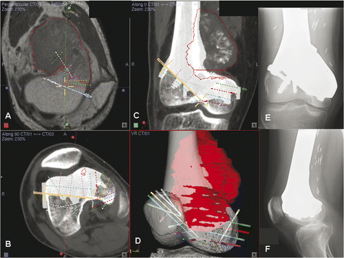
This 24-year-old patient had a low-grade sarcoma involving the right distal femur. Knee range of motion was 20° to 90°. CT and MRI scans of the femur () showed that a joint-saving intercalated tumor resection was possible. A preoperative CAD/CAM virtual resection of the femur bone model was performed using the MIMICS software (), and the skeletal defect was reconstructed using a CAD custom tumor prosthesis in which the design was built up on the exact dimensions of the proximal and distal osteotomies (). The planned tumor resection and prosthetic reconstruction were then converted back into DICOM format and imported into an intraoperative CT-based navigation system (). A medial subvastus approach was used: the collateral and cruciate ligaments of the knee were preserved, and the neurovascular bundles were free from the tumor. The locations and orientations of the multi-planar osteotomies were then defined using navigated drills on the distal femur, and the site of the proximal osteotomy was also marked by diathermy under navigational guidance. The tumor was then resected en bloc using oscillating saws and fine osteotomes. The custom prosthesis fitted well at the bone junctions. The patient had a satisfactory recovery of function, and was able to walk unaided with a normal gait at 3 months post-surgery. At one year following surgery, plain radiographs showed osseointegration at the bone-implant junctions, and there was no evidence of local recurrence of the tumor ().
Figure 7. For Patient 3, sagittal (A) and coronal (B) MR images showed a low-grade parosteal osteosarcoma involving the right distal femur. The tumor mainly involved the anterior part of the medial femoral condyle; the lateral and posteromedial femoral condyles were spared. It was therefore possible to precisely plan a multi-planar resection that preserved the lateral collateral ligaments at the lateral femoral condyle and also the insertion of the cruciate ligments at the femoral intercondylar notch. These soft tissue attachments are important for knee stability and the blood supply of the distal femur bone remnants when a joint-sparing tumor resection and reconstruction is contemplated. The resection was planned and simulated on the reconstructed 3D distal femur model in the MIMICS software (C).
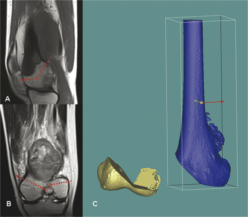
Figure 8. A CAD custom joint-saving prosthesis of the distal femur (C) was designed and manufactured based on the exact dimensions of the bone defect created in the virtual tumor resection. Posterior (A) and anterior (B) views of the 3D CAD model of the planned reconstruction are shown. With the help of this model, surgeons and implant engineers could discuss more effectively the choice of fixation at the distal prosthetic junction (length/direction of screws and extracortical plates). The CAD design and the actual prosthesis at the distal junction are shown in (D) and (E), respectively. The cutting flutes provided additional stability for fixation, and a coating of hydroxyapatite (white) was used to facilitate osteointegration at the proximal and distal prosthetic junctions.
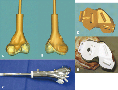
Figure 9. Preoperative screen images of surgical navigation planning on the navigation monitor. (A) shows the extent of the tumor (red dotted line) in the sagittal-view CT-MR image fusion. As back-conversion of the prosthesis from CAD to DICOM format was possible, the CAD prosthesis could be integrated into the navigation planning by CT-CT/prosthesis image fusion. Axial (B) and coronal (C) images illustrate the appearance of the prosthesis (in white) in the planning. This integration greatly facilitated the precise definition of multi-planar osteotomies at the distal femur. (D) shows the reconstructed 3D bone tumor model with the planes of resection defined by virtual pedicle screws. Use of CAD/CAM surgical planning and intraoperative navigational guidance enabled accurate tumor resection and precise fitting of the complex CAD prosthesis, as confirmed by postoperative plain radiographs (E and F).
Discussion
Precise surgical planning is fundamental to modern orthopaedic surgery. Complex bone deformity correction and musculoskeletal tumor surgery require accurate and detailed preoperative analysis and planning. Plain radiographs and CT scans provide imaging information in a 2D format; surgeons must mentally integrate this 2D information into a 3D model for surgical planning. Although CAD/CAM software allows surgeons to perform virtual surgical simulations based on preoperative image data sets, successful implementation of the surgical planning during the actual procedure is still dependent on the surgeons’ experience. The difficulty increases with the complexity of a given case. Our report suggests that a method combining the use of both CAD/CAM software and a surgical navigation system could help surgeons reproduce preoperative virtual surgical planning reliably in complex deformity corrections and in bone tumor resections with custom prosthetic reconstruction.
Unfortunately, commercially available surgical navigation systems only accept medical imaging data in DICOM format and do not offer the option to perform complex surgical simulation on these data. CAD/CAM software can import medical imaging data in DICOM format to permit manipulation; however, the resulting surgical simulation is in the proprietary format of the software, making it incompatible for direct use in a surgical navigation system. Therefore, the function of the MIMICS® software that allows conversion of CAD back to DICOM format enables surgeons to execute complex virtual surgical simulations precisely using any CT-based surgical navigation system during the actual surgery. The back-conversion of CAD format to DICOM format for use in surgical navigation was first reported in the context of a craniomaxillofacial deformity correction Citation[8]. Our results suggest that a similar technique can also be applied to orthopaedic procedures.
Image fusion technology is already used for surgical navigation in the resection of head and neck tumors and musculoskeletal bone tumors Citation[11–13]. Fused CT, MRI and PET data sets can provide excellent 3D visualization of the anatomic location of tumors and the extent of their infiltration into surrounding tissues. We found that image fusion of both the original CT data sets and the virtual surgical plan data sets created from CAD/CAM software could enhance the capacity of surgical navigation in executing virtual surgical plans. Although the surgical navigation system used was incapable of real-time navigation of the mobilized bone segment, toggling the fused image data sets to data sets with virtual surgical plans allowed accurate final positioning of the mobilized bone segments in deformity correction. For surgical planning of the musculoskeletal tumor resection, image fusion of the virtual CT data sets with the custom prosthesis and the original CT data sets allowed accurate planning of the resection planes and thus precise fitting of the custom prosthesis to the residual bone segment after tumor resection.
CAD/CAM software has also been used in corrective osteotomy of malunited fractures of the upper extremities Citation[14]. A custom-made osteotomy template was designed and manufactured to reproduce the preoperative simulation during the actual surgery. However, not only are there additional costs associated with such templates, but surgeons might encounter difficulty in placing them exactly at the planned osteotomy locations. We found that visual feedback from the intraoperative navigation system allowed more precise identification of the planned osteotomy sites.
One group of neurosurgeons has reported navigated tumor resection followed by reconstruction of a large cranial bone defect using a custom implant (based on a preoperatively constructed stereolithographic model) in a one-step surgical procedure Citation[15]. CAD custom prostheses could also be inserted without the use of a stereolithographic model following navigation guided resection of musculoskeletal bone tumors Citation[9], Citation[10]; however, this required manual transfer of the electronic measurements from the CAD data sets of custom prostheses to the navigation system, so the resection level and plane on which the CAD prosthesis was planned were represented identically in the navigation system. The method described for patient 3 in the present study actually enables surgeons to perform any virtual tumor resection in CAD/CAM software, and then allows accurate fitting of a CAD custom prosthesis in a one-step operation that would have been difficult to achieve by the conventional method.
Our report has several limitations. The follow-up period of this study with three patients was short; long-term follow-up in a larger series is needed to evaluate the clinical importance of the new technique. The initial learning curve of the technique was steep, as it required surgeons who had prior experience in navigated surgery and additional resources for CAD/CAM software and navigation facilities. We therefore only use the technique for patients undergoing complex deformity correction or tumor resection requiring precise fitting of custom prostheses. It would be helpful to have dedicated CAD/CAM software for orthopaedic applications in deformity correction and tumor resection/reconstruction, as the steps in the virtual manipulation and back-conversion of image data sets from CAD to DICOM format were both tedious and time-consuming.
In conclusion, our study suggests that computer aided virtual surgery using computer modeling software, when combined with surgical navigation, enables complex deformity corrections and tumor resections with subsequent CAD custom prosthetic reconstruction to be performed as planned, and may therefore offer clinical benefits.
Acknowledgments
We acknowledge the great assistance of Mr. Rock Hu (Department Manager, Bio-Medical Engineering, Materialise China) and Mr. James Chen (Chief Representative Officer, Materialise China) in using the MIMICS software. The Materialise company did not fund or sponsor this research in any way that might create a conflict of interest. We also thank Mr Sudha Shunmugam and the design team (Stanmore Implants, 210 Centennial Avenue, Centennial Park, Elstree, WD6 3SJ, United Kingdom) for design and manufacture of the CAD custom prosthesis.
References
- Paley D, Tetsworth K. Mechanical axis deviation of the lower limbs. Preoperative planning of uniapical angular deformities of the tibia or femur. Clin Orthop Relat Res 1992, 280: 48–64
- Paley D, Tetsworth K. Mechanical axis deviation of the lower limbs. Preoperative planning of multiapical frontal plane angular and bowing deformities of the femur and tibia. Clin Orthop Relat Res 1992, 280: 65–71
- Paley D, Chaudray M, Pirone AM, Lentz P, Kautz D. Treatment of malunions and mal-nonunions of the femur and tibia by detailed preoperative planning and the Ilizarov techniques. Orthop Clin North Am 1990; 21(4)667–691
- Jamali AA. Digital templating and preoperative deformity analysis with standard imaging software. Clin Orthop Relat Res 2009; 467(10)2695–2704
- Fortin T, Isidori M, Bouchet H. Placement of posterior maxillary implants in partially edentulous patients with severe bone deficiency using CAD/CAM guidance to avoid sinus grafting: A clinical report of procedure. Int J Oral Maxillofac Implants 2009; 24(1)96–102
- Li WZ, Zhang MC, Li SP, Zhang LT, Huang Y. Application of computer-aided three-dimensional skull model with rapid prototyping technique in repair of zygomatico-orbito-maxillary complex fracture. Int J Med Robot 2009; 5(2)158–163
- Chapuis J, Schramm A, Pappas I, Hallermann W, Schwenzer-Zimmerer K, Langlotz F, Caversaccio M. A new system for computer-aided preoperative planning and intraoperative navigation during corrective jaw surgery. IEEE Trans Inf Technol Biomed 2007; 11(3)274–287
- Pham AM, Rafii AA, Metzger MC, Jamali A, Strong EB. Computer modeling and intraoperative navigation in maxillofacial surgery. Otolaryngol Head Neck Surg 2007; 137(4)624–631
- Wong KC, Kumta SM, Chiu KH, Cheung KW, Leung KS, Unwin P, Wong MC. Computer assisted pelvic tumor resection and reconstruction with a custom-made prosthesis using an innovative adaptation and its validation. Comput Aided Surg 2007; 12(4)225–232
- Wong KC, Kumta SM, Chiu KH, Antonio GE, Unwin P, Leung KS. Precision tumour resection and reconstruction using image-guided computer navigation. J Bone Joint Surg Br 2007; 89(7)943–947
- Leong JL, Batra PS, Citardi MJ. CT-MR image fusion for the management of skull base lesions. Otolaryngol Head Neck Surg 2006; 134(5)868–876
- Nemec SF, Donat MA, Mehrain S, Friedrich K, Krestan C, Matula C, Imhof H, Czerny C. CT-MR image data fusion for computer assisted navigated neurosurgery of temporal bone tumors. Eur J Radiol 2007; 62(2)192–198
- Wong KC, Kumta SM, Antonio GE, Tse LF. Image fusion for computer-assisted bone tumor surgery. Clin Orthop Relat Res 2008; 466(10)2533–2541
- Murase T, Oka K, Moritomo H, Goto A, Yoshikawa H, Sugamoto K. Three-dimensional corrective osteotomy of malunited fractures of the upper extremity with use of a computer simulation system. J Bone Joint Surg Am 2008; 90(11)2375–2389
- Della Puppa A, Mottaran R, Scienza R. Image-guided cranial osteoma resection and bioceramic porous hydroxyapatite custom-made reconstruction in a one-step surgical procedure. Technical notes and illustrative case. Acta Neurochir (Wien) 2010; 152(1)155–159
