Abstract
During computer navigated total knee arthroplasty, pin holes are drilled in the femur and tibia to allow the placement of navigation trackers, and fractures associated with these pin holes have recently been reported. We hypothesized that an increase in stress around the pin holes is one of the most relevant factors contributing to the fracture. In this study, we used finite element analysis to investigate the stresses around femoral pin holes with respect to the mode of pin penetration, the diameter of the pin holes, and the degree of osteoporosis. Our results indicate that increases in pin hole diameter and reduction in bone strength as a result of osteoporosis intensify the stresses around the pin holes, especially in cases of transcortical pin penetration.
Introduction
In total knee arthroplasty (TKA), reliable lower extremity alignment and correct implant positioning are essential for a successful surgical outcome. Malpositioning of the tibial component in the frontal plane corresponds to a high incidence of implant loosening and failure Citation[1]. Implants with misalignment of more than 3° have a 24% risk of loosening by three years after surgery, whereas correctly aligned implants have only a 3% chance of loosening Citation[2], Citation[3]. Computer navigation has been increasingly used to perform accurate resections of the femur and tibia, to achieve soft tissue balancing, and to correct the positioning and alignment of implants Citation[4]. Most navigation systems use one, two, or three pins attached to the femur and tibia, to which the trackers are affixed, to determine the position of the femoral head center and of the femur and tibia during surgery. A popular commercial navigation system such as the Stryker Navigation System (Stryker Leibinger, Inc., Kalamazoo, MI) uses three trackers positioned on the iliac crest, distal femur, and proximal tibia Citation[5]. Each tracker is mounted over an anchoring pin that consists of a self-tapping screw designed to preserve rigid fixation during surgery Citation[5].
Pin holes are drilled to permit the placement of the navigation trackers during computer navigated TKA, and bone fractures associated with pin holes have been reported. Ossendorf et al. Citation[6] first reported a distal femoral stress fracture through the pin holes for the trackers. Subsequently, Jung et al. Citation[7] presented two cases of stress fracture associated with transcortical pin penetration; Bonutti et al. Citation[8] and Wysocki et al. Citation[9] reported femoral fractures through a pin hole where a tracker had been placed; and Li et al. Citation[10] presented a peri-prosthetic fracture extending through a pin hole. Even though the incidence of such fractures is low (approximately 1%), it is necessary to investigate the mechanisms by which they occur as these are serious injuries that require additional surgical management and hospitalization.
We hypothesized that an increase in stress around the pin holes is one of the most relevant factors contributing to the fracture; however, no biomechanical studies have been conducted to examine stresses concentrated around pin holes. In this study, we used finite element analysis to investigate the stresses around femoral pin holes with respect to the mode of pin penetration, the diameter of the pin holes, and the degree of osteoporosis.
Materials and methods
Computed tomography (CT) scanning with 1-mm slice thickness was performed on the femur of a healthy 21-year-old male subject with a height of 175 cm. A solid model of the femur was reconstructed using 3D-Doctor® software (Able Software Corporation, Lexington, MA) to detect the boundary edge of each slice and Rapidform™ software (INUS Technology, Inc., Seoul, Korea) to stack the slices and convert the images into an IGES-type model. A finite element model was then developed from the solid model using FEMAP® version 8.2 software (UGS Inc., Plano TX) (). The femoral model consists of cortical bone, cancellous bone, and an intramedullary canal. The material properties of the bony models were obtained from the literature Citation[11], Citation[12]. The inner and outer bone edges were identified by the gray-scale level at each CT slice based on consultation with anatomists. The cortical and cancellous bone were assumed to have elastic moduli of 15.5 GPa and 279 MPa, respectively, and Poisson's ratios of 0.3 and 0.3, respectively.
Figure 1. Finite element model of a femur with loading and boundary conditions (A) and four different modes of pin penetration in tubular bone: unicortical (B), bicortical (C), half-bicortical, (D) and transcortical (E).
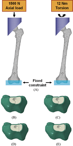
Finite element models of four pin penetration modes in tubular bone, including unicortical, bicortical, half-bicortical, and transcortical penetration, were developed according to the findings of a clinical report Citation[7] (). In the half-bicortical penetration case, the pin hole was placed in the middle of the bicortical and transcortical penetration points. For these four pin penetration modes, a pin-hole diameter of 4 mm and patient age of 20 years were considered as a base model. Then, three pin-hole diameters (3 mm, 4 mm and 5 mm) were substituted into the model to investigate the effect of diameter size on the likelihood of stress fractures. Each pin hole was placed 70 mm from the distal end of the femur. Different elastic modulus values and ultimate stress data were used for the cortical and cancellous bones for patients at 60, 70 and 80 years of age, obtained from previous experimental study, to investigate the effect of osteoporosis on the likelihood of stress fractures Citation[11], Citation[12]. The elastic moduli were 14.3 GPa, 14.0 GPa and 13.7 GPa for cortical bone and 145 MPa, 115 MPa and 79 MPa for cancellous bone at 60, 70 and 80 years of age, respectively, while moduli of 15.5 GPa and 279 MPa for cortical and cancellous bones, respectively, were used for 20 years of age. The ultimate stresses were 122, 98, 91 and 85 MPa for cortical bone at 20, 60, 70 and 80 years of age, respectively.
An axial compressive force of 1500 N and an axial torsion of 12 Nm were applied at the femoral head through a cylindrical jig while the bone was rigidly fixed 20 mm proximal from the distal end of the femur to simulate a previous experimental study Citation[13] (). The finite element analysis was performed using ABAQUS™/Standard 6.5 (ABAQUS, Inc., Providence, RI). An ordinary desktop personal computer with a quad core of 2.40 GHz was used not only for the modeling process but also for the analysis process. Maximum von Mises stresses were calculated, where von Mises stress is a criterion used to predict failure of a material. The maximum stress for a model with pin holes was normalized to the maximum stress in an intact model at the position where the maximum stress was detected in a model with pin holes. In addition, the ratio of maximum von Mises stress to ultimate stress was estimated. These values were compared with respect to penetration mode, pin-hole diameter, and degree of osteoporosis.
Results
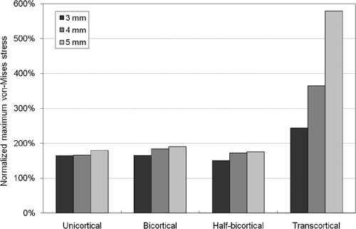
With both axial compressive and torsional loads, concentrated von Mises stress occurred around the pin holes (). The highest stresses were shown to result from transcortical penetration in both loading cases. The maximum stresses in unicortical, bicortical, half-bicortical, and transcortical penetrations at 20 years of age were 8.4–9.8 MPa, 18.6–19.4 MPa, 16.0–16.8 MPa and 17.4–34.1 MPa, respectively, under axial compressive load, and 9.6–10.5 MPa, 9.7–11.1 MPa, 8.8–10.2 MPa and 14.2–33.8 MPa, respectively, under torsional load. The normalized maximum stresses in unicortical, bicortical, half-bicortical, and transcortical penetrations at 20 years of age were 123.6–144.6%, 194.6–203.0%, 167.8–172.4% and 182.1–357.6%, respectively, under axial compressive load, and 164.7–179.4%, 165.9–190.1%, 150.3–175.3% and 243.6–579.6%, respectively, under torsional load. In axial compressive loading, unicortical penetration resulted in relatively lower stress values than those for the other penetration modes. An increase in pin diameter from 3 mm to 5 mm elevated the maximum stresses by 17.0%, 1.1%, −2.4% and 96.4% under axial compressive load () and by 9.0%, 14.6%, 16.7% and 138.0% under torsional load () in unicortical, bicortical, half-bicortical, and transcortical penetrations, respectively.
Figure 2. The von Mises stresses under 12 Nm of torsional load at the femoral head for transcortical pin penetration with pin diameter of 4 mm.

Figure 3. Maximum von Mises stresses at the pin hole normalized to the maximum von Mises stresses in the intact model for different pin penetration modes and pin diameters for 1500 N of axial compressive load at the femoral head.
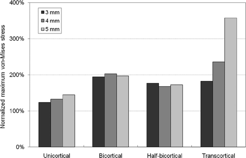
Figure 4. Maximum von Mises stresses at the pin hole normalized to the maximum von Mises stresses in the intact model for different pin penetration modes and pin diameters for 12 Nm of torsional load at the femoral head.
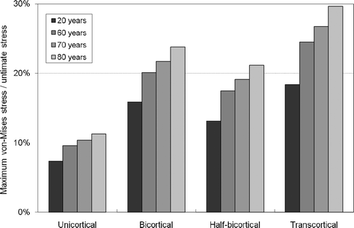
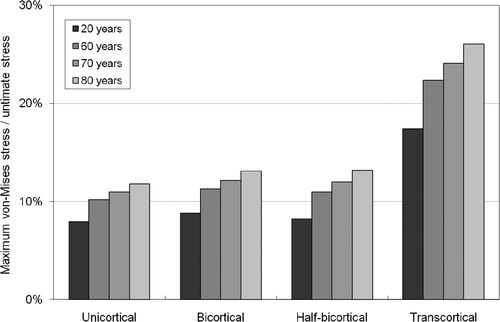
The ratios of maximum von Mises stresses to ultimate stresses were 7.4–11.3%, 15.8–23.8%, 13.1–21.2% and 18.4–29.6% under axial compressive load () and 7.9–11.8%, 8.8–13.1%, 8.2–13.2% and 17.4–26.0% under torsional load () from 20 to 80 years of age for unicortical, bicortical, and transcortical penetrations, respectively. In cases of transcortical penetration, the fracture risk ratio was dramatically elevated under both axial and torsional loads.
Discussion
Computer navigation systems have been used in TKA because they provide more accurate component positioning for better clinical results and safer surgical procedures. Although there are a few navigation systems that do not require the insertion of pins into the femur and tibia for the fixation of trackers to detect bone positions during surgery, most navigation systems do use such pins. Pin holes are a type of bone defect and a clinically relevant cause of bone stress that may increase fracture risk. There have been several experimental studies conducted to quantify the effects of cortical defects on femoral weakening: Brooks et al. Citation[14] reported that a bicortical screw hole of up to 30% of the bone diameter increased the stress concentration by 60%, while McBroom et al. Citation[15] found a reduction in strength in canine femora with unicortical holes. In addition, there have recently been reports Citation[6–10] of the occurrence of femoral or tibial fractures secondary to the pin holes during computer navigated TKA. However, these were clinical cases, not experimental studies, and the reports lacked the quantitative aspects, such as measurements of the maximum concentrated stress, necessary to predict the fracture risk around pin holes. In the present study, we investigated the concentrated stress around the femoral pin holes as a parameter of fracture risk with respect to the mode of pin penetration, the diameter of the pin holes, and the degree of osteoporosis.
As pin-hole diameters increased from 3 mm to 5 mm, maximum stresses increased by approximately 10% in unicortical, bicortical, and half-bicortical penetrations and by more than 100% in transcortical penetrations under both axial compressive and torsional loads. This data coincides with the results of previous studies Citation[14], Citation[15] demonstrating that increases in cortical defects could elevate levels of concentrated stress. Based on the above findings, the use of smaller pins would be beneficial in reducing stress concentration around the pin holes. However, since smaller pins may be more likely to loosen during computer navigated TKA, reasonable diameters must be carefully identified. Bonutti et al. suggested the use of smaller pins, such as 3 mm, with double pin-fixated trackers instead of a single 5-mm bicortical pin penetration.
Transcortical pin penetration resulted in the highest levels of stress regardless of pin-hole diameter or degree of osteoporosis under both loading cases. In addition, the effects of increasing pin diameter or osteoporosis on stress levels were more acute in cases of transcortical penetration. It can be hypothesized that this phenomenon results from the fact that transcortical penetration produces a larger cortical defect than the other penetration modes. This hypothesis is supported by clinical data from Jung et al. Citation[7], who reported two fracture cases through pin holes in which transcortical pin penetration was presumed to be the main influence. Transcortical penetration should also be avoided because it can result in higher risks of thermal bone necrosis Citation[7].
Osteoporosis increases the concentration of stress with respect to ultimate stress for all pin penetration modes, especially for transcortical penetration under both axial compressive and torsional loads. The maximum stress reached approximately 30% and 26% of the ultimate stress under axial compressive load and torsional load, respectively, in simulated patients 80 years of age. Although these stress levels were below the ultimate stress levels, repetitive stress may result in stress fractures through the pin holes. The fact that most cases of fracture through pin holes have been reported in elderly female patients, who are more likely to suffer from osteoporosis, supports our interpretation. In addition, we modeled pin holes under the assumption that they were drilled as perfect circles without any micro-cracks. Since micro-cracks around a pin hole could cause additional stress concentrations, the possibility of a stress fracture through the pin hole may be elevated.
The presented study suffers from some limitations. Even though the finite element femoral model we developed was based on CT images taken from an actual patient, the material properties used in the finite element analysis were obtained from the literature Citation[11], Citation[12]. Moreover, all of our models were based on a single subject. A series of models derived from subjects in each age group incorporating patient-specific anatomical and material properties should be included in future studies. It would also be valuable to simulate a dynamic situation, such as an entire gait cycle, that reflects complicated loading conditions to obtain more realistic results. Other biomechanical factors associated with fracture risk should also be investigated to improve clinical relevance. The position of the pin holes, the number of pins used, and/or the direction of insertion could be important factors affecting the fracture risk. The pin-hole position and the number of pins used will be considered in our next study.
In conclusion, increases in pin-hole diameter and reductions in bone strength due to osteoporosis were shown to intensify the concentrated stresses, especially in cases of transcortical pin penetration, resulting from the placement of pin holes for fixation of trackers during computer navigated TKA. The transcortical pin penetration mode resulted in the highest stress regardless of loading cases and strengthened the effect of pin-hole diameter and osteoporosis on the likelihood of fracture. We therefore recommend that clinicians avoid transcortical pin penetration. In addition, appropriate pin-hole diameters should be identified because smaller pins result in lower levels of concentrated stress but also incur higher risks of loosening during computer navigated TKA.
Acknowledgment
This work was supported by a Korea Science and Engineering Foundation (KOSEF) grant funded by the Korean government (MEST) (R01-2008-000-20352-0) and the 2009 National Agenda Project (NAP) funded by the Korea Research Council of Fundamental Science & Technology.
References
- Lotke PA, Ecker ML. Influence of positioning of prosthesis in total knee replacement. J Bone Joint Surg Am 1977; 59(1)77–79
- Fehring TK, Odum S, Griffin WL, Mason JB, Nadaud M. Early failures in total knee arthroplasty. Clin Orthop Relat Res 2001; 392: 315–318
- Jeffery RS, Morris RW, Denham RA. Coronal alignment after total knee replacement. J Bone Joint Surg Br 1991; 73(5)709–714
- Laskin RS, Beksaç B. Computer-assisted navigation in TKA: Where we are and where we are going. Clin Orthop Relat Res 2006; 452: 127–131
- Marchant DC, Rimmington DP, Nusem I, Crawford RW. Safe femoral pin placement in knee navigation surgery: A cadaver study. Comput Aided Surg 2004; 9(6)257–260
- Ossendorf C, Fuchs B, Koch P. Knee. Femoral stress fracture after computer navigated total knee arthroplasty. Knee 2006; 13(5)397–399
- Jung HJ, Jung YB, Song KS, Park SJ, Lee JS. Fractures associated with computer-navigated total knee arthroplasty. A report of two cases. J Bone Joint Surg Am 2007; 89(10)2280–2284
- Bonutti P, Dethmers D, Stiehl JB. Case report: Femoral shaft fracture resulting from femoral tracker placement in navigated TKA. Clin Orthop Relat Res 2008; 466(6)1499–1502
- Wysocki RW, Sheinkop MB, Virkus WW, Della Valle CJ. Femoral fracture through a previous pin site after computer-assisted total knee arthroplasty. J Arthroplasty 2008; 23(3)462–465
- Li CH, Chen TH, Su YP, Shao PC, Lee KS, Chen WM. Periprosthetic femoral supracondylar fracture after total knee arthroplasty with navigation system. J Arthroplasty 2008; 23(2)304–307
- McCalden RW, McGeough JA, Barker MB, Court-Brown CM. Age-related changes in the tensile properties of cortical bone. The relative importance of changes in porosity, mineralization, and microstructure. J Bone Joint Surg Am 1993; 75(8)1193–1205
- McCalden RW, McGeough JA, Court-Brown CM. Age-related changes in the compressive strength of cancellous bone. The relative importance of changes in density and trabecular architecture. J Bone Joint Surg Am 1997; 79(3)421–427
- Papini M, Zdero R, Schemitsch EH, Zalzal P. The biomechanics of human femurs in axial and torsional loading: Comparison of finite element analysis, human cadaveric femurs, and synthetic femurs. J Biomech Eng 2007; 129(1)12–19
- Brooks DB, Burstein AH, Frankel VH. The biomechanics of torsional fractures. The stress concentration effect of a drill hole. J Bone Joint Surg Am 1970; 52(3)507–514
- McBroom RJ, Cheal EJ, Hayes WC. Strength reductions from metastatic cortical defects in long bones. J Orthop Res 1988; 6(3)369–378
