Abstract
Three-dimensional rotational X-ray imaging with the SIREMOBIL Iso-C3D (Siemens AG, Medical Solutions, Erlangen, Germany) has become a well-established intra-operative imaging modality. In combination with a tracking system, the Iso-C3D provides inherently registered image volumes ready for direct navigation. This is achieved by means of a pre-calibration procedure. The aim of this study was to investigate the influence of the tracking system used on the overall navigation accuracy of direct Iso-C3D navigation.
Three models of tracking system were used in the study: Two Optotrak 3020s, a Polaris P4 and a Polaris Spectra system, with both Polaris systems being in the passive operation mode. The evaluation was carried out at two different sites using two Iso-C3D devices. To measure the navigation accuracy, a number of phantom experiments were conducted using an acrylic phantom equipped with titanium spheres. After scanning, a special pointer was used to pinpoint these markers. The difference between the digitized and navigated positions served as the accuracy measure.
Up to 20 phantom scans were performed for each tracking system. The average accuracy measured was 0.86 mm and 0.96 mm for the two Optotrak 3020 systems, 1.15 mm for the Polaris P4, and 1.04 mm for the Polaris Spectra system. For the Polaris systems a higher maximal error was found, but all three systems yielded similar minimal errors.
On average, all tracking systems used in this study could deliver similar navigation accuracy. The passive Polaris system showed – as expected – higher maximal errors; however, depending on the application constraints, this might be negligible.
Introduction
Three-dimensional rotational X-ray has become a well-accepted intra-operative imaging modality. Equipped with tracking hardware, such systems can provide inherently registered image volumes ready for direct navigation. The automatic registration is usually based on a pre-calibration procedure that needs be performed only once. During navigation, the device-specific calibration data is used to determine the scanned subject's registration matrix. The combination of calibration and intra-operative scanning poses a complex navigation scenario, as described in detail in the next section.
Direct navigation with the SIREMOBIL Iso-C3D (Siemens Medical Solutions, Erlangen, Germany), a widely used rotational X-ray system, was evaluated by Ritter et al. Citation[1]. Under conditions similar to those in clinical practice, they measured an average accuracy of approximately 1.6 mm. In their study, the authors used passive navigation with a Polaris P4 system (Northern Digital, Inc., Waterloo, Ontario, Canada), but suggested that the application of tracking systems with greater accuracy would significantly increase the navigation accuracy in turn. Other groups have investigated the navigation accuracy of similar devices. For example, van de Kraats et al. measured the accuracy of a prototype mobile propeller C-arm (Pulsera with motorized propeller facility; Philips Medical Systems, Best, The Netherlands) to be approximately 1 mm Citation[2]. For their experiments they used a StealthStation Treon (Medtronic, Louisville, CO) with passive tracking.
The current study aims to investigate the influence of the tracking system on the overall accuracy of direct Iso-C3D navigation. To quantify this impact, the navigational accuracy was measured under clinically relevant conditions in a series of phantom experiments. For these trials, two different types of optical tracking system were used: the Optotrak 3020 system and two position sensors from the Polaris system family (all from Northern Digital, Inc.).
Materials and methods
The principle of direct Iso-C3D navigation
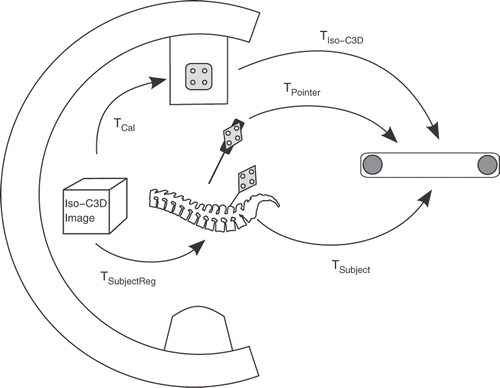
The Iso-C3D provides CT-like image volumes, inherently registered to the reference base attached to the patient's anatomy. During image acquisition, the navigation system measures the position and orientation of the Iso-C3D relative to the subject. It then calculates the registration matrix of the scanned subject based on the device-specific calibration matrix TCal. To determine this transformation, a calibration must be performed once, using the procedure outlined in . At calibration, a plastic phantom containing radio-opaque markers is scanned. The geometric properties of the phantom relative to the attached reference base are well known from its manufacture. Therefore, the transformation TPhantomReg can be determined directly from the phantom scan, and the device calibration matrix TCal can then be calculated according to the formulaDuring navigation, the device calibration matrix TCal is used to determine the subject's registration matrix TSubjectReg by applying the formula
summarizes the transformations involved in a general navigation scenario. The indicated pointer represents a surgical tool used to navigate within the acquired image volume. This requires the transformation of the tool's position into the image space by calculating
Together with the necessary pre-calibration, direct Iso-C3D navigation poses a rather complex navigation scenario.
Figure 1. The Iso-C3D calibration procedure requires scanning of a special phantom containing radio-opaque markers. The calibration matrix TCal is determined for a certain start position of the Iso-C3D. The determination is done automatically by the Iso-C3D system software.
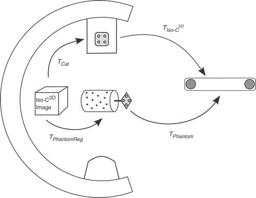
Figure 2. When scanning a subject, the navigation system can easily calculate the registration matrix TSubjectReg by measuring the transformations TSubject and TIso-C3D when the Iso-C3D is in its pre-calibrated start position. The complete navigation scenario is shown, including an abstract pointing tool.
Accuracy evaluation of direct Iso-C3D navigation
To evaluate the accuracy of direct Iso-C3D navigation using different tracking systems, a number of phantom experiments were carried out. Two types of tracking systems by Northern Digital, Inc., were used for the evaluation: the Optotrak 3020 system and the Polaris P4/Spectra (“Polaris P4” is not the official product name; however, it is used throughout this paper to enable distinction between the Polaris Spectra and its predecessor). The Optotrak 3020 uses infrared light-emitting diodes (LEDs) strobing at a high frequency. The RMS accuracy is specified as 0.1 mm in the x-y direction and 0.15 mm in the z direction, with the z-axis being the viewing axis of the camera.
The Polaris P4 system has a specified RMS accuracy of 0.35 mm, while the overall volume RMS accuracy of the Polaris Spectra sensors is specified as 0.25 mm. The Spectra is the successor to the Polaris P4 system. Both cameras are available in a hybrid version that is capable of tracking infrared LEDs as well; however, throughout the experiments the cameras were used exclusively in the passive mode. In this operation mode, the cameras emit infrared light that is reflected by retroreflective markers. For the evaluation, custom-made dynamic reference bases (DRBs) were used, equipped with spherical retroreflective markers (BrainLAB AG, Feldkirchen, Germany).
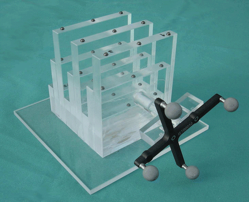
To establish a clinically relevant experimental setup, the Iso-C3D as well as the position sensor were relocated between each experiment, as suggested by Ritter et al. Citation[1] and van de Kraats et al. Citation[2]. The evaluation phantom was then placed in the iso-center of the Iso-C3D. The phantom contains 27 titanium spheres of 4 mm diameter, arranged in a regular 3 × 3 × 3 grid (). The spheres are mounted to a carrier made from acrylic glass with an attachment mechanism for active and passive DRBs.
Figure 3. The phantom used in the presented study. It is made of acrylic glass and carries 27 titanium markers arranged in a regular 3 × 3 grid. Here it is shown equipped with a passive reference base.
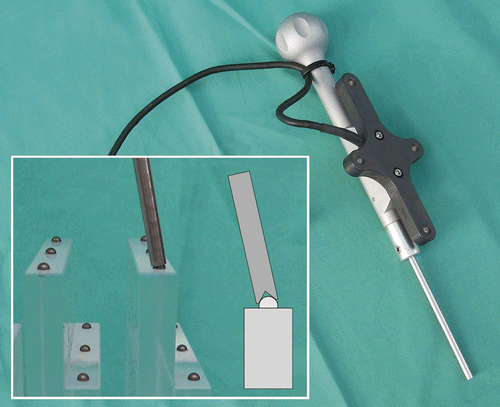
After each scan, the fiducial marker positions were digitized. The pointer used has a conically shaped indentation at the tip which perfectly fits the marker spheres (). The pointer allows for very high digitization precision throughout the measurements, since it can be calibrated very accurately and is sure to be placed correctly on the fiducial marker. Because of its high placement accuracy and rigidity, the pointer allows for observer-independent measurements.
Figure 4. The pointer used for digitizing the fiducial marker positions. In this case it is being used with an active reference base. The pointer has a hollow tip that matches the marker spheres exactly.
After digitization, the fiducial marker positions were automatically detected using a software module based on the open-source platform MARVIN Citation[3]. To detect the marker positions, the reconstructed image is blurred by a Gaussian kernel with the standard deviation set to the sphere radius (2 mm). The local maxima are then searched in the blurred volume. Finally, the sphere positions are determined with sub-voxel accuracy by calculating the center of mass of the detected sphere.
The accuracy of direct Iso-C3D navigation was then determined by calculating the distance between the detected and digitized fiducial marker positions. The root mean square error (RMSE) was calculated for every experiment according to the formulawhere
contains the digitized fiducial marker centers in the DRB coordinate system,
contains the detected positions in the reconstructed image volume, and TReg is the subject's registration matrix. The number of fiducial markers is specified by n.
The experiments were carried out using two Iso-C3D devices at two sites: the facilities of the MEM Research Center at the University of Bern (referred to as site 1), and the Veterinary Clinic at the University of Zurich (referred to as site 2). A total of four cameras were used: an Optotrak 3020 and a Polaris P4 at site 1, and an Optotrak 3020 and a Polaris Spectra at site 2. Both Iso-C3D devices were calibrated using the method outlined in the previous sub-section.
Results
lists the results of the phantom experiments. In the case of the Optotrak 3020 system at site 2, only seven scans could be performed because the availability of the tracking system was limited. All other results are based on 20 scans per camera type. The table lists the minimal, maximal and mean RMS errors. Additionally, displays the results as a box plot.
Figure 5. Plot showing the distribution of the measured RMS errors summarized in . Note that the values for the Optotrak system at site 2 are based on only seven scans as opposed to 20 scans for the other cameras.
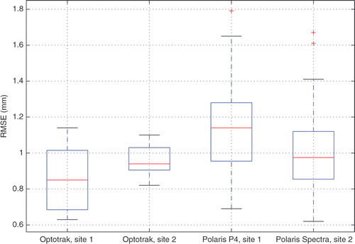
Table I. Root mean square errors (RMSE) for the conducted experiments. In each experiment an Iso-C3D scan was performed and up to 27 fiducial marker positions were compared using the subject's registration matrix.
The results presented in show a higher maximal RMSE as well as a wider spread of the measured accuracy for both passive systems compared to the Optotrak 3020. However, the maximal difference between the mean accuracies is only 0.3 mm (Polaris P4 versus Optotrak 3020, site 1). Further analysis showed a statistically significant difference only between the Polaris P4 and the Optotrak 3020 system at site 1 (p < 10−3, Wilcoxon rank-sum test). All other combinations revealed no significant differences with respect to the 1% and 5% levels.
Discussion
In this study, the accuracy of direct Iso-C3D navigation was evaluated using three different optical tracking systems. Ritter et al. Citation[1] had previously investigated the accuracy, but using only a Polaris P4 system. In a clinical set-up they measured an average accuracy of 1.6 mm. In the current study, in addition to the Polaris P4 system, an Optotrak 3020 and a Polaris Spectra system were used in order to quantify the influence of the tracking system on the overall system accuracy. In the case of the P4 camera, the average accuracy measured was 1.15 mm, which is better than the 1.6 mm reported by Ritter et al. A number of factors may have led to such a difference in the results, such as the use of a highly accurate pointer in the current study. However, as the test set-ups used in this and the previous studies were quite complex, identifying specific reasons for those differences would be speculative.
In general the measured accuracy values are in accordance with expectations, considering the single marker accuracy Citation[4] of the different camera types. In fact, the highest errors were measured with the Polaris P4 camera, which also has the lowest single marker accuracy. Furthermore, clearly shows a wider variation in the navigational accuracy of the passive Polaris systems compared to the Optotrak 3020. also shows that the use of the Spectra system led to a lower maximal error and less variation in the measured errors compared to the P4 system. This seems logical since the Polaris Spectra system is the successor to the P4 systems and a further development thereof.
This study demonstrates that in direct Iso-C3D navigation the tracking system used has a minor influence on the overall navigation accuracy. In fact, the Iso-C3D device itself seems to introduce the largest errors. Of course, this only holds true for the three tracking systems evaluated in this study. That being said, considering daily clinical practice where tools such as navigated drills are used in addition, the measured accuracy differences might even become negligible.
In conclusion, all the evaluated tracking systems provide similar average Iso-C3D navigation accuracy. As expected, both passive systems showed more varying results compared to the Optotrak 3020 system. If maximal accuracy is required, the Optotrak 3020 outperforms the passive Polaris systems. Nonetheless, in a clinical or research scenario, other constraints such as space limitations and ease of use may be more important than pure navigational accuracy.
References
- Ritter D, Mitschke M, Graumann R. Markerless navigation with the intra-operative imaging modality Siremobil Iso-C3D. Electromedica 2002; 02(1)31–36
- van de Kraats EB, Carelsen B, Fokkens WJ, Boon SN, Noordhoek N, Niessen WJ, van Walsum T. Direct navigation on 3D rotational X-ray data acquired with a mobile propeller C-arm: Accuracy and application in functional endoscopic sinus surgery. Phys Med Biol 2005; 50(24)5769–5781
- Rudolph T, Puls M, Anderegg C, Ebert L, Broehan M, Rudin A, Kowal J. MARVIN: A medical research application framework based on open source software. Computer Methods and Programs in Biomedicine 2008; 91(2)165–174
- Wiles AD, Thompson DG, Frantz DD. Accuracy assessment and interpretation for optical tracking systems. Proceedings of SPIE Medical Imaging 2004; 5367: 421–432