Abstract
Accurate placement of cannulated screws is essential to ensure fixation of medial femoral neck fractures. The conventional technique may require multiple guide wire passes, and relies heavily on fluoroscopy. A computer-assisted planning and navigation system based on 2D fluoroscopy for guide wire placement in the femoral neck has been developed to improve screw placement. The planning process was supported by a tool that enables a virtual radiation-free preview of X-ray images. This is called “zero-dose C-arm navigation”. For the evaluation of the system, six formalin-fixed cadaveric full-body specimens (12 femurs) were used. The evaluation demonstrated the feasibility of fluoroscopically navigated guide wire and implant placement. Use of the novel system resulted in a significant reduction in the number of fluoroscopic images and drilling attempts while achieving optimized accuracy by attaining better screw parallelism and enlarged neck-width coverage. Operation time was significantly longer in the navigation assisted group. The system has yielded promising initial results; however, additional studies using fractured bone models and with extension of the navigation process to track two bone fragments must be performed before integration of this navigation system into the clinical workflow is possible, and these studies should focus on reducing the operation time.
Introduction
The incidence of surgery in patients with hip fractures is increasing with the demographic increase in geriatric patients Citation[1]. Closed reduction and internal fixation with three screws forming an equilateral triangle is an accepted method for the surgical treatment of medial femoral neck fractures Citation[2], Citation[3]. Exact screw placement with a wide screw spread enables a biomechanically stable fixation, and the number of drilling attempts should be kept to a minimum as this might weaken the cortical and cancellous bone and lead to subtrochanteric fractures Citation[4], Citation[5]. Adhering to these guiding principles requires extensive fluoroscopic radiation exposure, however, and the extensive use of fluoroscopy is a concern for both the patient and the operating team Citation[6], Citation[7]. Nevertheless, despite good results with this technique, primary incorrectly positioned screws and secondary fracture dislocations have been reported in 10-50% of cases Citation[8], Citation[9]. Furthermore, the need to rotate the C-arm fluoroscope in order to visualize the anteroposterior (AP) and lateral plane of the proximal femur may prolong the operation time and endanger sterility.
Computer-assisted navigation has been used in trauma surgery to improve the accuracy of guide wire placement for positioning cannulated screws and dynamic hip screws (DHS) while reducing the number of drilling attempts and radiation exposure Citation[10–13]. Although a significant reduction in fluoroscopy time has been reported, more than two X-ray images were usually necessary to achieve optimal orientation of the AP and lateral projections of the proximal femur for planning the guide wire position Citation[10–13].
A novel computer-assisted surgical planning and navigation system based on 2D fluoroscopy was developed at the Chair of Medical Engineering of the Helmholtz-Institute for Biomedical Engineering at the RWTH Aachen University, in cooperation with SurgiTAIX AG (Aachen, Germany), as an intraoperative guidance system for navigated guide wire placement in the femoral neck and head. To support the image acquisition process, the surgeon is supported by so-called “zero-dose C-arm navigation”. This tool enables a virtual radiation-free preview of the X-ray images of the femoral neck and head as well as the actual orientation of the C-arm relative to the predefined frontal and lateral planes. Thus, the acquisition of useless or sub-optimal image projections can be avoided Citation[14]. During in vitro and cadaver evaluations in previous studies, use of this novel computer-assisted fluoroscopy-based planning and navigation system has resulted in enhanced accuracy in positioning the guide wire and subsequently the DUROM™ hip resurfacing prosthesis (Zimmer GmbH Germany, Freiburg, Germany) Citation[15], Citation[16]. Our intention was to evaluate the newly developed system in a trauma application.
This paper presents the results of a cadaver study undertaken to evaluate the functionality and accuracy of this system. We hypothesized that cannulated screw insertion using our computer-assisted method would decrease radiation exposure to the minimum of two images and reduce the number of drilling attempts. Furthermore, the accuracy of implant placement might be improved in comparison to the conventional method, and the operation time shortened. As navigated fracture reduction was not the focus of this study, non-fractured femora were used.
Materials and methods
For the evaluation of the system, six formalin-fixed cadaveric full-body specimens were used (). The placement of three cannulated screws (6.5 mm, Fa. DePuy, Kirkel-Limbach, Germany) into each of six femoral necks, in accordance with the manufacturer's recommended workflow using the conventional fluoroscopic technique, was performed by a single surgeon (group 1). No parallel drill guide was used. The same surgeon (a 6th-year orthopaedic resident) then placed three cannulated screws into each of a further six femoral necks guided by the computer-assisted surgical planning software (group 2).
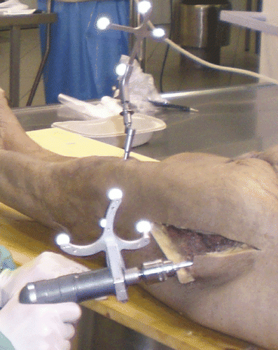
Figure 1. Operative set-up showing the dynamic reference base fixed on the distal femur and image guided freehand navigation of the guide wire into the femoral neck.
For conventional screw placement, the surgeon used a C-arm fluoroscope (Iso-C3D®, Siemens, Erlangen, Germany) in conventional 2D mode. Using a power drill, a guide wire (Kirschner wire; 3.2 mm in diameter) was gradually advanced using a freehand technique under optimal image intensification in two planes until the subchondral bone of the femoral head was reached. After measuring the length, a cannulated drill bit was used to drill the appropriate canal, after which the correct 6.5-mm cannulated screw was inserted over the guide wire. We performed this procedure for the other two screws in a similar manner, attempting to form an equilateral triangle with one side close to Shenton's arch. The guide wires were then removed.
To plan and perform the guide wire placement for inserting the cannulated screws in the femoral neck, we developed a computer-assisted planning and navigation system based on optical tracking as well as on intraoperative calibrated X-ray images. This system has been implemented on the basis of a navigation module library from SurgiTAIX AG (Aachen, Germany) Citation[14]. After fixation of the dynamic reference base (DRB) on the distal part of the femur by means of a Schanz screw, the surgeon executed the following five planning and navigation steps:
Step 1: Non-rigid registration for FOV determination and “zero-dose C-arm navigation”
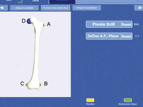
To enable intuitive, image guided freehand navigation of the guide wire during the navigation step, the field of view (FOV) was defined by the surgeon in order to avoid eye-hand coordination problems during navigation. Therefore, percutaneous palpation of three femoral landmarks was performed. We used the most lateral as well as the most medial point of the transepicondylar axis and the greater trochanter to compute the eye-hand coordinate transformation for an intuitive representation of the tracked tools during guide wire navigation (step 4) (). Additionally, during the image acquisition step, these points are used for non-rigid point-to-point registration of a simplified shape model necessary for “zero-dose C-arm navigation” (SurgiTAIX, Aachen, Germany) Citation[14]. The third computation on the basis of the three registration points was the determination of the AP and lateral planes, which were required during the subsequent image acquisition step.
Figure 2. Field of view (FOV) registration points (in green) defined by the surgeon to determine the reference frame for his eye-hand coordination. The blue point represents the tip of the guide pin.
Step 2: X-ray image acquisition
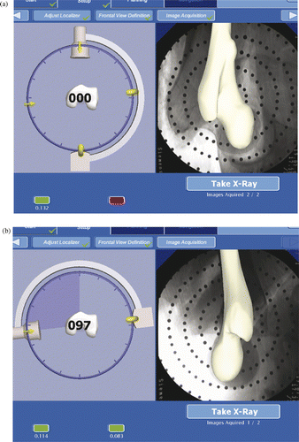
For intraoperative planning of the implant placement, a minimum of two calibrated X-ray images from different projection directions (the AP and lateral planes) are necessary. Here, the surgeon was supported by the “zero-dose C-arm navigation.” Zero-dose C-arm navigation enables a virtual radiation-free preview of the X-ray images as well as the actual orientation of the C-arm relative to the predefined (step 1) frontal and lateral planes (). Thus, the acquisition of X-ray images projecting undesired directions and incomplete or non-relevant structures could be avoided.
Figure 3. Image acquisition with zero-dose C-arm navigation. (a) Preview of frontal view (with acquired image in background). (b) Preview of lateral view (with acquired image in background).
Step 3: Definition of the safe zone
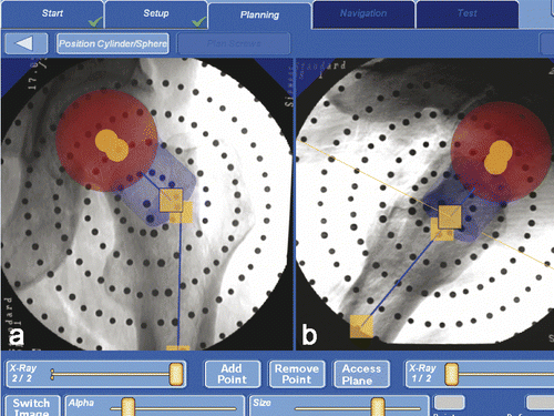
The definition of the 3D “safe zone” in the femoral neck and femoral head supported the surgeon in safely planning the final position of the cannulated screws during the implant alignment step (step 4). The surgeon's task was to alter the size, position and orientation of a cylinder in the femoral neck and of a sphere in the femoral head via a touch screen in such a way that the cylinder and sphere were positioned within the X-ray projection of the femoral neck and head in the frontal and lateral views (). Zimolong et al. indicated that femoral neck perforations could be avoided by approximating the femoral neck using a cylinder during 3D planning procedures Citation[17].
Figure 4. Definition of the safe zone: planning the implant position with the displayed safety cylinder (blue cylinder) and safety sphere (red sphere) in the frontal view (a) and lateral image (b).
Step 4: Implant alignment
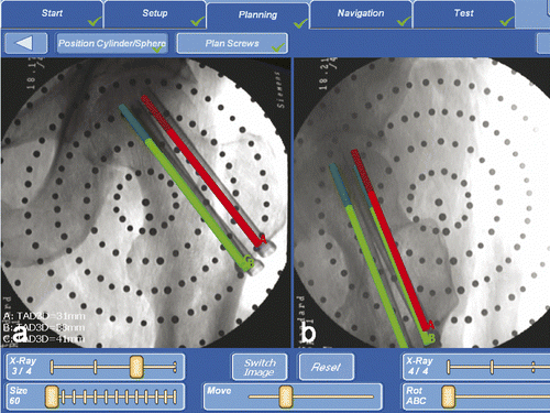
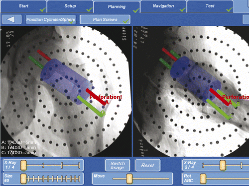
The positions of the three cannulated screws were defined on the AP and lateral X-ray projections in order to place the guide wires in optimal positions in relation to the anatomical structures as well as to each other (). Therefore, the surgeon used an image with the same size as the original blade. The goal of this planning step was to find valid implant positions forming an equilateral triangle with a maximum screw spread while avoiding femoral neck perforation or exceeding the femoral head, and a preferably steep implant alignment in relation to the proximal femoral shaft. If the surgeon left the “safe zone” during the planning procedure, he was warned by the “Perforation” caption ().
Figure 5. Planning of the screw position in the frontal (left) and lateral (right) image in the femoral neck without exceeding the femoral head.
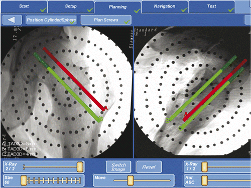
Figure 6. On leaving the safe zone the surgeon is warned by the appearance of the “Perforation” caption.
Step 5: Navigation of the guide wire
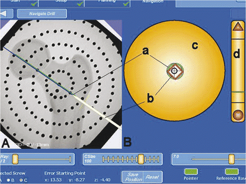
After the surgeon had defined satisfactory implant positions, image guided freehand navigation of the guide wire on the planned trajectory was performed. For exact placement of the guide wire in the femoral neck and head, the optical tracking system permanently tracked the position of the calibrated drilling machine, together with the rigidly fixed DRB of the femur (). During the navigation step, an X-ray projection with a virtual projection of the navigated guide wire in relation to the femur enabled plausibility checking. For a better adaption of the navigation step to the preferences of the surgeon, the crosshair navigation offers the possibility of changing the sensitivity of the display scale. Following guide wire placement, the operation followed the subsequent conventional operation steps according to the operating technique described above.
Figure 7. (A) Visualization of the image guided freehand navigation of the guide wire on the planned trajectory. (B) Display of two crosshair-like vectors for orientation of the navigation tool. The green circle (a) represents the position of the guide wire tip, and the red diamond (b) represents the position of a point on the guide wire axis. (c) is the crosshair-like representation of the online distance and direction from the guide wire tip to the axis of the planned trajectory (the diamond and circle in the center mean that the tool is aligned). (d) is a representation of the depth of the guide wire in relation to the lateral cortical bone.
Data collection and analysis
During each procedure, the following measurements were recorded:
The total number of fluoroscopic single shots taken to achieve optimal orientation of the AP and lateral planes of the proximal femur (step 2) and to attain an acceptable position for all screws.
The total number of drilling attempts. Every correction of the angle, including retrograde movement of the drill, was counted as a drilling attempt.
Screw parallelism and neck-width coverage as determined on conventional X-ray images to evaluate implant placement accuracy (the triangular area [in mm2] of the femoral neck held by the screws was calculated by the distances of the three screws from the center of the femoral neck). As in the evaluation of Hamelinck et al. Citation[10], the angle between the screws was documented, and points were awarded for the angle of placement in two directions as follows: 4 points for 0° to 3° deviation, 2 points for 3° to 6° deviation, and 0 points for 6° or greater deviation. All three screws were compared with one another.
The total duration of the operation. The time was measured from the moment of insertion of the first guide wire (group 1) or from fixation of the DRB (group 2) until all three screws were finally positioned.
All analyses were performed by the same investigator, who was blinded to the technique used and was presented with the images in a randomized order.
For statistical analysis we used the Student t-test. Values are presented as mean ± standard deviation (SD). p values < 0.05 were considered to be statistically significant. Evaluation was carried out using the statistics program Instat 3 for Windows XP.
Results
Computer-assisted fluoroscopy-based navigation did not have to be interrupted at any time or in any case. In all six cases, placement of the guide wire in the femoral neck and head under fluoroscopy-based navigation and the subsequent placement of three cannulated screws were successful (). The evaluation of the individual results of fluoroscopy-based navigation and of conventional screw placement is summarized in .
With computer assistance, the number of fluoroscopic single shots acquired to achieve acceptable positioning of all screws was reduced significantly by 89.6% (p < 0.001). Using the computer-guided system, only three drilling attempts were necessary for implant placement in all cases, while significantly more drilling attempts were made when using the conventional technique (8.2 ± 4.8; p < 0.05). Implant placement was significantly more accurate using the navigation system as screw parallelism was more precise (+58%; p < 0.05) and the neck-width coverage expanded (+61%; p < 0.05). However, computer assistance significantly increased the mean operation time by 67.9% (p < 0.05).
Discussion
The aim of this study was to test the utility of a novel computer-guided fluoroscopy-based planning and navigation system for supporting the surgeon in the planning and insertion of guide wires and cannulated hip screws. The system was compared to other 2D computer-assisted approaches that are already on the market ().
Table I. Comparison of the conventional fluoroscopic technique (Group 1) with the computer-assisted technique (Group 2). The values are given as the mean and standard deviation. Statistical significance was defined for *p < 0.05; **p < 0.001.
Table II. Comparison of 2D fluoroscopy-based navigation systems for navigating cannulated femoral neck screw placement. (CAS: Computer Assisted Surgery; COT: conventional operative technique. Statistical significance: *p < 0.05; **p < 0.001).
The evaluation of the system demonstrated the feasibility of fluoroscopy-based navigated guide wire and implant placement. Use of the novel system resulted in a significant reduction in the number of fluoroscopic images and drilling attempts while achieving optimized accuracy by attaining better screw parallelism and enlarged neck-width coverage. However, operation time was significantly extended compared to the conventional technique. Fluoroscopic image acquisition was efficiently supported by “zero-dose C-arm navigation”. In most cases, only two X-ray images were used to locate an optimum AP and lateral view of the proximal femur. During guide wire and screw placement, no confirmatory fluoroscopic images were required. Only in the first two cadavers operated on using the computer-assisted technique were additional X-rays acquired (two and one, respectively). In each of the four subsequent computer-assisted operations, only two X-rays in total were required besides the two X-rays for final implant documentation. This might reflect a learning curve; it has to be taken into account that the operating surgeon initially had no prior experience with the system being evaluated. While using the conventional technique, every drilling attempt and every change in the K-wire direction had to be controlled fluoroscopically. With the navigation system, incorrect pathways for the guide wire were corrected “online” and no confirmatory fluoroscopic images were needed until the final implant position had been achieved. Thus, exposure to radiation during surgical treatment of this common fracture type was reduced, especially because there was no need for sub-optimal “test X-rays” to achieve an optimal view of the proximal femur in the two planes. If this approach is applied clinically, the reduction in the number of fluoroscopic images may have a vital impact on the patient, as the femoral neck is close to radiosensitive organs Citation[18]. The 89.6% reduction in radiation exposure achieved in our study might be greater than that obtained with other navigation systems used for inserting cannulated hip screws. However, such a comparison might be inappropriate, as we documented the number of fluoroscopic images acquired whereas other groups recorded the radiation exposure time.
This study shows that the first-pass accuracy for guide wire placement in the femoral neck was improved significantly with the system evaluated. The drilling attempts were reduced to the minimum of three required to place the cannulated screws, and the surgeon could trust the navigation system. This speaks in favor of the technique and may be regarded as an important advantage of computer-assisted insertion of cannulated hip screws. In clinical use, this approach may serve to minimize the need for revision surgery as a result of early failure of implant fixation in a femoral neck weakened by multiple incorrect guide wire pathways. The results are similar to those of other researchers who also performed computer-assisted guide wire placement in the femoral neck Citation[10], Citation[11], Citation[19]. In one of those studies Citation[11], one of 15 computer-assisted trials required a second pass because the surgeon did not follow the computer plan.
Concerning system accuracy, it was found that screw parallelism was significantly improved and neck-width coverage significantly enlarged. This might improve the stability of fracture fixation in a clinical application Citation[20], Citation[21]. As Kendoff et al. found that using a navigated mechanical parallel drill guide did not improve screw parallelism Citation[22], we did not use one in this study. The use of such a drill guide might also necessitate enlargement of the skin incision, as the guide must be placed close to the bone, while screw spread might be restricted due to the holes provided and anatomical variance of the femoral neck. While Liebergall et al. Citation[23] also improved screw parallelism and neck-width coverage using the StealthStation ION™ navigation system (Medtronic SNT, Louisville, CO) with the FluoroNav™ virtual fluoroscopy system, Kendoff et al. Citation[22] and Hamelinck et al. Citation[10] found that screw placement could not be improved using the VectorVision® system (BrainLAB, Heimstetten, Germany). The six navigated hips in the present study were too few to allow comparisons with the above-mentioned studies or to serve as a basis for a clinical outcomes study, but the analysis showed some advantage with our system. Additionally, the simplified shape model of the coxal end of the femur seemed to be sufficiently accurate to represent the physiological variation in the dimensions and configuration of the proximal femur.
Hamelinck et al. Citation[10] reported only marginally different operation times for the computer-assisted and conventional techniques, whereas Kendoff et al. Citation[22] reported increased procedure time for the navigated technique. The operation times in these studies cannot be compared directly, however, as the beginning and ending points of the operations were either different or not defined Citation[10], Citation[22]. Furthermore, it was not mentioned whether the surgeon had prior experience with the navigation system used. Fluoroscopic image acquisition supported by “zero-dose C-arm navigation” is a time-consuming process which nearly doubles the operation time. In our setting, the surgeon himself performed the four planning and navigation steps. In particular, tracking the position of the drilling machine in relation to the DRB involves a learning process. With further progress and an additional surgeon performing the planning steps, the longer operating time might be reduced. Consistent with the experience of Grützner et al. Citation[24], we are also of the opinion that only repeated use of navigation trains the operating surgeon adequately.
This study revealed some limitations. As the cadaveric full-body specimens were formalin-fixed, they were quite stiff, such that the lateral positioning of the upper leg could hardly be performed and skin incisions had to be enlarged for adequate guide wire navigation. For future cadaver studies, we plan to use Thiel-fixed cadaveric specimens. One potential criticism concerns the use of intact femora. Our computer system was only capable of tracking one bone fragment at once, as we only used a single DRB. Navigated reduction of both fracture fragments would clearly be desirable and is planned for the future. In addition, future developments should concentrate on the development of DRB fixation methods that provide a rigid but minimally invasive fixation to the bone. Still, this problem has not yet been resolved in this or any other study; invasive fixation techniques using Schanz screws are still the method of choice Citation[25].
In conclusion, the use of our computer-guided system for the placement of cannulated hip screws decreases the number of sub-optimal fluoroscopic images and guide wire passes required while optimizing screw parallelism and enlarging neck-width coverage by the cannulated screws. Computer-assisted surgery with our system increases the operation time and has just been tested in non-fractured femora. Although these results are promising, additional laboratory studies using fractured bone models in Thiel-fixed cadavers and with extension of the navigation process to tracking of two bone fragments should be undertaken. The studies should focus on reducing the operation time prior to possible integration of our navigation system into the clinical workflow.
Acknowledgments
The authors offer special thanks to the Department of Anatomy of the University of Bonn, Germany, under the direction of Professor Dr. K. Schilling and Dr. I Kinsky, for planning and conducting the cadaver study.
Declaration of interest: This study has been funded by the German Federal Ministry of Education and Research (BMBF) within the framework of the research program OrthoMIT through grants BMBF 01EQ0802, 01EQ0402 and 01IBE02C.
References
- Kannus P, Niemi S, Parkkari J, Palvanen M, Vuori I, Järvinen M. Hip fractures in Finland between 1970 and 1977 and predictions for the future. Lancet 1999; 353: 802–805
- Selvan VT, Oakley MJ, Rangan A, Al-Lami MK. Optimum configuration of cannulated hip srews for the fixation of intracapsular hip fractures: A biomechanical study. Injury 2004; 35: 136–141
- Bosch U, Schreiber T, Krettek C. Reduction and fixation of displaced intracapsular fractures of the proximal femur. Clin Orthop Relat Res 2002; 399: 59–71
- Maurer SG, Wright KE, Kummer FJ, Zuckerman JD, Koval KJ. Two or three screws for fixation of femoral neck fractures?. Am J Orthop 2003; 32: 438–442
- Lindequist S, Tornkvist H. Quality of reduction and cortical screw support in femoral neck fractures. An analysis of 72 fractures with a new computerized measuring method. J Orthop Trauma 1995; 9: 215–221
- Mehlman CT, DiPasquale TG. Radiation exposure to the orthopaedic surgical team during fluoroscopy: “How far away is far enough?”. J Orthop Trauma 1997; 11: 392–398
- Sanders R, Koval KJ, DiPasquale T, Schmelling G, Stenzler S, Ross E. Exposure of the orthopaedic surgeon to radiation. J Bone Joint Surg Am 1993; 75: 326–330
- Simpson AH, Varty K, Dodd CA. Sliding hip screws: modes of failure. Injury 1989; 20: 227–231
- Szita J, Cserhati P, Bosch U, Manninger J, Bodzay T, Fekete K. Intracapsular femoral neck fractures: The importance of early reduction and stable osteosynthesis. Injury 2002; 33: 41–46
- Hamelinck HKM, Haagmans M, Snoeren MM. Safety of computer-assisted surgery for cannulated hip screws. Clin Orthop Rel Res 2006; 455: 241–245
- Mayman D, Vasarhelyi EM, Long W, Ellis RE, Rudan J, Pichora DR. Computer-assisted guidewire insertion for hip fracture fixation. J Orthop Trauma 2005; 19: 610–615
- Hüfner T, Kfuri M, Kendoff D, Richter M, Geerling J, Krettek C. Navigated osteosynthesis of the proximal femur. An experimental study. Unfallchirurg 2003; 106: 975–979
- Chong KW, Wong MK, Rikhraj IS. The use of computer navigation in performing minimally invasive surgery for intertrochanteric hip fractures – The experience in Singapore. Injury 2006; 37: 755–762
- de la Fuente M, Belei P, Ohnsorge J, Skwara A, Radermacher K. Zero-dose C-arm navigation: An efficient approach based on virtual X-ray targeting. Int J CARS 2007; 2(Suppl 1)249–250
- Belei P, Skwara A, de la Fuente M, Schkommodau E, Fuchs S, Wirtz DC, Kämper C, Radermacher K. Fluoroscopic navigation system for hip surface replacement. Comput Aided Surg 2007; 12: 160–167
- Gravius S, Belei P, de la Fuente M, Radermacher K, Mumme T. Evaluation of a new fluoroscopy-based navigation system in the placement of the femoral component in hip resurfacing. Proc Inst Mech Eng H 2010; 224(4)565–576
- Zimolong A, Portheine F, Friedrichs D, Traub F, Radermacher K. Evaluation of deformable models for femoral neck surgery. Comput Aided Surg 2004; 9: 71–79
- Kwong L, Johanson PH, Zinar DM, Lenihan MR, Herman MW. Shielding of the patient's gonads during intramedullary interlocking femoral nailing. J Bone Joint Surg Am 1990; 72: 1523–1526
- Suhm N, Beck T, Zuna I, Marazzi C, Staedele H, Jacob AL, Messmer P, Regazzoni P. Fluoroscopy-based surgical navigation versus fluoroscopical guidance to control guide wire insertion for osteosynthesis of femoral neck fractures. Eur J Trauma 2004; 30: 23–28
- Gurusamy K, Parker MJ, Rowlands TK. The complications of displaced intracapsular fractures of the hip: The effect of screw positioning and angulation on fracture healing. J Bone Joint Surg Br 2005; 87: 632–634
- Kloen P, Rubel IF, Lyden JP, Helfet DL. Subtrochanteric fracture after cannulated screw fixation of femoral neck fractures: A case report of four cases. J Orthop Trauma 2003; 17: 225–229
- Kendoff D, Hüfner T, Citak M, Maier C, Wesemeier F, Pearle A, Krettek C. A new parallel drill guide for navigating femoral neck screw placement. Development and evaluation. Unfallchirurg 2006; 109: 875–880
- Liebergall M, Ben-David D, Weil Y, Peyser A, Mosheiff R. Computerized navigation for the internal fixation of femoral neck fractures. J Bone Joint Surg Am 2006; 88: 1748–1754
- Grützner PA, Langlotz F, Zheng G, von Recum J, Keil C, Nolte LP, Wentzensen A, Wendl L. Computer-assisted LISS plate osteosynthesis of proximal tibia fractures: Feasibility study and first clinical results. Comput Aided Surg 2005; 10: 141–149
- Kendoff D, Bogojevic A, Citak M, Citak M, Maier C, Maier G, Krettek C, Hüfner T. Experimental validation of non-invasive referencing in navigated procedures on long bones. J Orthop Res 2007; 25: 201–207
