Abstract
This study evaluated seven different frames of reference used for tibial component rotation in total knee arthroplasty (TKA) to determine which ones showed good reliability between bone specimens.
An optoelectronic system based around a computer-assisted surgical navigation system was used to measure and locate 34 individual anatomical landmarks on 40 tibias. Each particular frame of reference was reconstructed from a group of data points taken from the surface of each bone. The transverse axis was used as the baseline to which the other axes were compared, and the differences in angular rotation between the other six reference frames and the transverse axis were calculated.
There was high variability in the tibial rotational alignment associated with all frames of reference. Of the references widely used in current TKA procedures, the tibial tuberosity axis and the anterior condylar axis had lower standard deviations (6.1° and 7.3°, respectively) than the transmalleolar axis and the posterior condylar axis (9.3° for both).
In conclusion, we found high variability in the frames of reference used for tibial rotation alignment. However, the anterior condylar axis and transverse axis may warrant further tests with the use of navigation. Combining different frames of reference such as the tibial tuberosity axis, anterior condylar axis and transverse axis may reduce the range of errors found in all of these measurements.
Introduction
In total knee arthroplasty (TKA) the rotational alignment of the tibial component remains an unresolved problem Citation[1]. The tibial component has been shown to have a wider range of rotation than the femoral one Citation[2]. Various techniques are used to ensure optimal alignment, but there is a lack of reliability and repeatability Citation[1]. In a study of 109 TKAs, 50% were found to have tibial malrotation of more than 5° Citation[3], which is sufficient to result in knee pain, a poor range of motion and instability Citation[4], Citation[5]. Moreover, rotational malalignment causes abnormal eccentric loading of the tibial component during flexion of the knee, when the femur rides upwards on the disk-shaped tibial components. Such eccentric loading will greatly reduce the forces necessary to loosen the prosthesis Citation[4]. In fixed-bearing TKA designs, medial rotation of the tibia can adversely affect patellofemoral tracking and can cause patellar dislocation Citation[6].
A reference for tibial rotation has to fulfil two important criteria: it must be reliably identifiable and an accurate and true representation of the natural rotation of the proximal end of the tibia Citation[1]. In positioning the prosthetic tibial tray in the transverse plane, two factors need to be considered: the “optimal” bone coverage and the extensor apparatus alignment Citation[7]. Optimal bone coverage is achieved when the tibial component covers most of the underlying tibial plateau, i.e., when it provides a maximal cortical bearing and even load distribution over the plateau Citation[8]. However, rotational positioning of the tibial tray can be difficult, especially in fixed-bearing knee designs, because of the desire to maximize tibial bone coverage while obtaining proper alignment of the TKA components. It has been reported that rotational alignment along the posterior tibial condyles resulted in the maximum amount of bone coverage but also in an internally rotated tibial tray Citation[9].
Currently, two techniques are widely used for rotational alignment of the tibial component in TKA. The first uses anatomical landmarks, whereby the tibial component is centered on the tibial tuberosity (or slightly medial to it) to align it with the primary motor of the knee, the quadriceps mechanism. Any deviation from this position tends to apply inappropriate rotational forces to the implant Citation[4], Citation[10]. The second approach, which avoids reference to anatomical landmarks, is the range-of-movement (ROM) technique, in which the knee is put through a full range of flexion and extension, allowing the trial tibial implant to orient itself in the best position relative to the femoral component Citation[11]. The anatomical landmark technique has been reported to be reliable and reproducible by some authors Citation[12], Citation[13] but not by others Citation[1]. The ROM technique has been reported to be inappropriate for alignment of the tibial component as it leaves the component more internally rotated Citation[11].
The aim of this study was to evaluate seven different frames of reference used for tibial component rotation in TKA and determine which references showed good reliability between bone specimens.
Materials and methods
This research was completed at the Laboratory of Human Anatomy at the University of Glasgow, under the 2006 (Scotland) Amendment to the Human Anatomy Act and therefore did not require review by an Ethics Committee.
Forty tibias were sampled from a large bone library at the Laboratory of Human Anatomy, University of Glasgow. The bones selected were of unknown age, sex and race; 16 were from the right side and 24 from the left side. Bones that were either poorly preserved or traumatically deformed, or that had arthritic disease of sufficient degree to compromise accurate measurements, were excluded from the study.
An optoelectronic system based around the OrthoPilot® computer-assisted surgical navigation system (Aesculap, Tuttlingen, Germany) was used, with the software customized to collect multiple data points using the standard anatomical landmark identification code. Aesculap had provided the customized software used in this system to the senior author for use in research. The system consisted of a Polaris optical localizer and tool interface unit (TIU) (Northern Digital, Inc., Waterloo, Ontario, Canada), two rigid-body active markers containing light-emitting diodes (LEDs) (Aesculap), a laptop computer (Hewlett-Packard Company, Palo Alto, CA), and a foot control (steute Schaltgeräte GmbH & Co. KG, Löhne, Germany) ().
Figure 1. Arrangement of equipment showing the orientation of the bone specimen and the position of the rigid-body active markers.
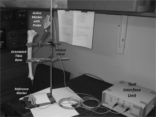
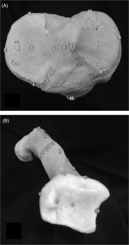
Each bone was positioned using two clamps that were connected to a vertical stand. On the stand each tibia was held upright in its natural proximal-to-distal position with the anterior surface facing the camera. One rigid body was securely connected to the bottom of the vertical stand and used as a reference marker in relation to the other rigid body. A pointed probe was attached to the other rigid body and used to locate the anatomical landmarks on the bones. Each landmark was recorded as a set of three-dimensional Cartesian coordinates. The computer interface allowed the position and orientation of the instrument to be displayed on the screen, aiding the accurate acquisition of landmark coordinates. To determine the linear and angular dimensions of the parameters to be measured, 34 anatomical landmarks (points) were chosen on each tibia ().
Figure 2. Digitized points of interest on the tibial plateau (A) and on the anterior and distal surfaces of the tibia (B). For further description, see the Materials and methods section.
All landmarks were collected by one observer (S.R.P.). The intra-observer variability of the method had already been calculated previously by taking ten repeat measurements of the posterior condylar axis and trans-epicondylar axis on a single femur.
Geometric constructions
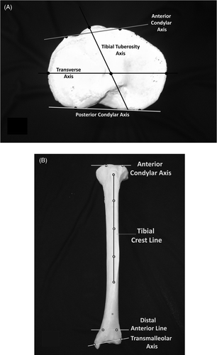
Seven different axes were obtained based on the data points taken from the tibial surface ():
The transverse axis (TA) is the line from the most lateral point on the lateral condyle through the knee center to the most medial point on the medial side of the condyle Citation[10].
The posterior condylar axis (PCA) is the line through the most posterior points on the lateral and medial condyles Citation[14].
The anterior condylar axis (ACA) is the line through the most anterior points on the lateral and medial condyles Citation[15].
The tibial tuberosity axis (TTA) is the line from the peak of the tibial tuberosity to the knee center on the tibial plateau Citation[16].
The transmalleolar axis (TMA) is the line from the most prominent point on the medial malleolus to the midpoint between the two points on the lateral side of the distal tibia which articulates with the fibula Citation[17].
The tibial crest line (TCL) is the line drawn from the peak of the tibial tuberosity to the most distal prominent point on the tibia Citation[1].
The distal anterior line (DAL) is an extra-articular line drawn through the most prominent anterior distal points on the medial and lateral surface of the tibia.
Figure 3. The proximal (A), anterior and distal (B) frames of reference on the tibial plateau.
Data were analysed using SPSS 17.0 (SPSS, Inc., Chicago, IL) and Excel 2003 (Microsoft Corp., Redmond, WA) to calculate descriptive statistics for each axis.
Results
Intra-observer variability showed a standard deviation (SD) of 0.5° and a range of 1.8° for the repeated measurement of the angle between the posterior condylar axis and trans-epicondylar axis on a single femur. This was taken as satisfactory evidence of intra-observer reliability.
There was high variability in the tibial rotational alignment associated with all frames of reference (). The axis with the lowest variability was the TTA, with an SD of 6.1°. The PCA was externally rotated 5° on average from the reference axis (TA). The rotational alignment with respect to the reference axis ranged from 98° of external rotation (TCL) to 42° of internal rotation (TMA) (). Two of the four reference frames used in TKA procedures (ACA, TTA) had the lowest standard deviations; however, the TMA and PCA (both widely used in current TKA) showed larger standard deviations. Of the two axes not routinely used in TKA, the TCL had a smaller SD than either the TMA or PCA but the DAL had the highest SD.
Figure 4. Box plot of tibial rotational alignment for six frames of reference relative to the TA. From left to right, these are the anterior condylar axis (ACA), distal anterior line (DAL), posterior condylar axis (PCA), tibial crest line (TCL), transmalleolar axis (TMA), and tibial tuberosity axis (TTA).
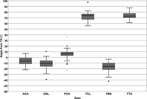
Table I. Rotation of frames of reference with respect to the transverse axis. (Negative values represent internal rotation and positive values represent external rotation.)
Discussion
In the TKA literature there is more evidence concerning accurate rotational alignment of the femoral component than the tibial component Citation[9], Citation[10]. In fixed-bearing TKA designs, internal rotation of the tibia adversely affects the patellofemoral tracking and can cause patellar dislocation Citation[6]. Dalury reported that internal or external tibial rotation could lead to impingement on the polyethylene surface, which could lead in turn to loss of motion and possibly wear Citation[18].
The aim of this study was to measure the different frames of reference used for tibial component rotation in TKA. If a frame of reference is to be of genuine use, it must co-vary with other landmarks and axes in a predictable manner. This study did not show compelling reliability for any of the tibial-derived axes nor even permit the ranking of axes in terms of relative superiority. In a similar study using ten cadavers and anatomic landmarks, Siston et al. Citation[1] also showed high variability in tibial rotational alignment. They described five techniques for landmark data collection using a navigation system to control the tibial rotation alignment and none of them showed any advantages over the others Citation[1]. The large variation in tibial landmarks has been noted by others; for example, Mizu-uchi et al. found a large variation in the ideal angle of tibial alignment in their CT-based navigation system study Citation[19].
The present study has a number of limitations. Firstly, the absolute accuracy of the landmark acquisition is unknown. The error of the system used is given as 1 mm by the manufacturer (Aesculap), but the accuracy with which individual landmarks are identified was not measured. Small errors in locating landmarks can lead to significant errors in anatomical reference frames: In TKA, a 7-mm anteroposterior error in identifying one of the femoral epicondyles could correspond to approximately 5° of rotational error in the transverse plane Citation[20]. Another limitation is that the bones sampled were of unknown age, sex and race, and therefore may not be representative of the population of actual tibias encountered in operations. An in vivo comparison with recording of demographic information would further strengthen the findings.
Of all the measured frame-of-reference angles, we found that the TTA, a reference commonly used in the operating theater, had the smallest range (26.2°) of any axis, which would accredit to its routine use in the alignment of the tibial component. The SD of our measurements (6.1°) was slightly greater than that reported in the literature (2.6° to 5.4°) Citation[3], Citation[16], Citation[21], but it should be noted that the TTA did not have any outliers when the data were represented by a box plot. We also found an average angle of 16° between the tip of the tibial tuberosity and the TA, which corresponds to the ideal tibial component orientation of 18° from the tibial tuberosity as given by Berger et al. in support of the use of this axis Citation[16]. However, despite being a satisfactory landmark in many cases, the TTA can be difficult to locate with a single point in some patients.
The ACA exhibited a lower standard deviation (7.3°) and therefore also seems to be a reliable reference with a small range (29°). It also had no outliers on the box plot. The ACA may be a landmark of interest for the rotational alignment of the tibial component as it is readily accessible and easy to palpate, and this may justify further study to investigate its potential use in navigated surgery.
For the TMA the range of 39° was larger, and this could explain some tibial malalignment in TKAs performed using this reference axis. Akagi et al. Citation[22] reported that the anteroposterior axis was more reliably identified on CT images than the TMA, whereas other authors found their results for this axis to be more consistent when using particular methods, such as those involving osteometric apparatus (24° ± 9.3°) Citation[3] or CT-based scanning (28° ± 10.0°) Citation[23], and these findings are similar to our own results (). However, Eckhoff et al. found that, when using the TMA to measure tibial torsion, it showed less variation, ranging from 15° to 30° Citation[24].
The PCA had a standard deviation of 9.3° and the highest range of 59°. Eckhoff et al. found the TA, with respect to the PCA, to be externally rotated by 5° ± 1° Citation[25], so their mean measurement was similar to our result. The box plot of the data clearly shows that this reference has a tight inter-quartile range, which may explain why it is widely used in TKA operations to guide tibial component alignment. However, the distribution of outliers indicates that the PCA is not reliable in all cases.
The reference axis of the TCL described by Siston et al. showed similar results to the TMA, with one outlier increasing the range so that the SD was lower than for both the TMA and PCA. Siston et al. indicated potential errors when using these landmarks Citation[1], but found a standard deviation of 10.8°, higher than our result of 7.9°. They also found the TCL to be more precise than those techniques referencing the tibial tubercle, which was not confirmed in this study.
The DAL also showed a large range and the highest SD. It is felt that precise access to the DAL would also be difficult to obtain in the operating theater setting due to the soft tissue coverage of that area.
During TKA surgery, experienced surgeons use multiple landmarks to guide the positioning of the components. Navigation relies on the accuracy of the landmarks and axes in the same way as manual instrumentation Citation[20]. However, in symptomatic OA patients, where there are degenerative changes such as bone defects, osteophytes and dysplasia, or in revision TKA, several of the “conventional” landmarks may be absent or deformed. This may lead to aberrant geometry and changes to the conventionally used axes, so there is a requirement to find substitute landmark(s) such as those described above. Combining references has been shown to be a successful solution on the femoral side in TKA Citation[1], and this study suggests that a similar approach may be advantageous for adjusting tibial rotation.
In conclusion, we found high variability in the tibial frames of reference used for tibial rotation alignment. Despite remaining a satisfactory landmark in many cases, the TTA can be difficult to locate with a single point in some patients. Therefore, the ACA and TA may warrant further tests involving navigation systems as they are accessible and clearly detectable at all times. Combining different frames of reference, such as the TTA, ACA and TA, may reduce the range of errors whilst still using practical landmarks that are identifiable in surgery.
Acknowledgments
The authors wish to thank the technical staff at the Laboratory of Human Anatomy, University of Glasgow, BBraun Aesculap for the loan of the equipment, Jean-Baptiste Pinzuti of SAS Aesculap for processing of the data and Andrew Johnston for help with the manuscript.
Declaration of interest: Mr Picard has licences and patents with BBraun Aesculap, and the Department of Orthopaedics at Golden Jubilee National Hospital has received research grants from BBraun Aesculap. However, no direct funding was received for the research reported in this paper.
References
- Siston RA, Goodman SB, Patel JJ, Delp SL, Giori NJ. The high variability of tibial rotational alignment in total knee arthroplasty. Clin Orthop Relat Res 2006; 452: 65–69
- Asano T, Akagi M, Koike K, Nakamura T. In vivo three-dimensional patellar tracking in the femur. Clin Orthop Relat Res 2003; 413: 222–232
- Uehara K, Kadoya Y, Kobayashi A, Ohashi H, Yamano Y. Bone anatomy and rotational alignment in total knee arthroplasty. Clin Orthop Relat Res 2002; 402: 196–201
- Bargren J. Total knee dislocation due to rotatory malalignment of the tibial component: A case report. Clin Orthop Relat Res 1980; 147: 271
- Dorr LD, Boiardo RA. Technical considerations in total knee arthroplasty. Clin Orthop Relat Res 1997; 205: 5–11
- Nagamine R, Whiteside LA, Otani T, White SE, McCarthy DS. Effect of medial replacement of the tibial tubercle on patellar position after rotational malposition of the femoral component in total knee arthroplasty. J Arthroplasty 1996; 11: 104–110
- Lemaire PD, Pioletti PF, Meyer R-M, Meuli J, Dörfl P, Leyvraz F. Tibial component positioning in total knee arthroplasty: Bone coverage and extensor apparatus alignment. Knee Surg Sports Traumatol Arthrosc 1997; 5: 251–257
- Incavo SJ, Ronchetti PJ, Howe JG, Tranowski JP. Tibial plateau coverage in total knee arthroplasty. Clin Orthop Relat Res 1994; 299: 81–85
- Incavo SJ, Coughlin KM, Pappas C, Beynnon BD. Anatomic rotational relationships of the proximal tibia, distal femur, and patella: Implications for rotational alignment in total knee arthroplasty. J Arthroplasty 2003; 18: 643–648
- Cobb JP, Dixon H, Dandachli W, Iranpour F. The anatomical tibial axis: Reliable rotational orientation in knee replacement. J Bone Joint Surg Br 2008; 90: 1032–1038
- Ikeuchi M, Yamanaka N, Okanoue Y, Ueta E, Tani T. Determining the rotational alignment of the tibial component at total knee replacement. J Bone Joint Surg Br 2007; 89: 45–49
- Akagi M, Oh M, Nonaka T, Tsujimoto H, Asano T, Hamanishi C. An anteroposterior axis of the tibia for total knee replacement. Clin Orthop Relat Res 2004; 420: 213–219
- Coughlin KM, Incavo SJ, Churchill DL, Beynnon BD. Tibial axis and patellar position relative to the femoral epicondylar axis during squatting. J Arthroplasty 2003; 18: 1048–1055
- Insall JN. Surgical techniques and instrumentation in total knee arthroplasty. Surgery of the knee., 2nd, JN Insall, RE Windsor, WN Scott, MA Kelly, P Aglietti. Churchill-Livingstone, New York 1993; 739–804
- Moller JT, Hvid I. Tibial plateau strength patterns in experimental modular knee replacement. Arch Orthop Trauma Surg 1985; 104: 57–61
- Berger RA, Crosset LS, Jacobs JJ. Malrotation causing patellofemoral complications after total knee arthoplasty. Clin Orthop Relat Res 1998; 356: 144–153
- Mizu-uchi H, Matsuda S, Miura H, Higaki H, Okazaki K, Iwamoto Y. The effect of ankle rotation on cutting of the tibia in total knee arthroplasty. J Bone Joint Surg Am 2006; 88: 2632–2636
- Dalury DF. Observations of the proximal tibia in total knee arthroplasty. Clin Orthop Relat Res 2001; 389: 150–155
- Mizu-uchi H, Matsuda S, Miura H, Okazaki K, Akasaki Y, Iwamoto Y. The evaluation of post-operative alignment in total knee replacement using a CT-based navigation system. J Bone Joint Surg Br 2008; 90: 1025–1031
- Siston RA, Giori NJ, Goodman SB, Delp SL. Surgical navigation for total knee arthroplasty: A perspective. J Biomech 2007; 40: 728–735
- Yoshioka Y, Siu DW, Scudamore RA, Cooke TD. Tibial anatomy and functional axes. J Orthop Res 1989; 7: 132–137
- Akagi M, Mori S, Nishimura S, Nishimura A, Asano T, Hamanishi C. Variability of extra-articular tibial rotation references for total knee arthroplasty. Clin Orthop Relat Res 2005; 436: 172–176
- Takai S, Sakakida K, Yamashita F, Suzu F, Izuta F. Rotational alignment of the lower limb in osteoarthritis of the knee. Int Orthop 1985; 9: 209–216
- Eckhoff DG, Johnson KK. Three-dimensional computed tomography reconstruction of tibial torsion. Clin Orthop Relat Res 1994; 302: 42–46
- Eckhoff DG, Johnston RJ, Stamm ER, Kilcoyne RF, Wiedel JD. Version of the osteoarthritic knee. J Arthroplasty 1994; 9: 73–79