Abstract
Objective: Registration of ultrasound to computed tomography (CT) images is used in several image-guided procedures, including laparoscopic surgery and radiation therapy. Conventional approaches use an external tracker calibrated to the ultrasound transducer and CT system, but several calibration steps are required. Registration can also be performed by aligning image features between modalities, but differences in feature depiction make matching difficult and initial approximate alignment is often needed. Registration using fiducials is a simpler approach but is limited by the need to implant fiducials in the anatomical region of interest so they are visible to both ultrasound and CT. This paper investigates the feasibility of using fiducials near the skin surface, and whether such fiducials can be sufficiently localized in the very near field of a 3D ultrasound transducer without significantly degrading image quality. This approach can also be used as an initialization step for feature-based registration techniques.
Materials and Methods: A stand-off pad containing fiducials (n > 3) was constructed using polyvinyl chloride and steel ball fiducials that are visible in both 3D ultrasound and CT images. Experiments on phantoms were performed to assess image quality and registration errors. Controlled variables included pad thickness and ultrasound imaging parameters. Initial tests were also conducted of a potential application in partial nephrectomy surgery.
Results: Image quality was degraded by an average of 6-11-13% (elevational-axial-lateral) in resolution of point targets and 5% in lesion contrast. Average fiducial localization error was 1.34 mm (axial) to 2.38 mm (lateral and elevational); average fiducial registration error (FRE) was 0.46 mm (axial), 1.08 mm (lateral) and 0.90 mm (elevational); and average total registration error (TRE) was 1.84 mm (axial), 0.89 mm (lateral) and 3.31 mm (elevational). Clinical results showed a similar FRE to that in the phantom study, but with an average TRE of 14.04 mm (over three patients). Ultimate alignment of the organ boundaries was affected mainly by motion from respiration.
Conclusions: The small loss of image quality from the fiducial stand-off pad and the minimal inconvenience of using the pad at the time of the CT scan may be a worthwhile trade-off for purposes of registration since the pad provides a registration accuracy of several millimeters while still allowing subsequent feature-based registration. Future research will focus on using the registration from the fiducial stand-off pad for deformable feature-based registration of 3D ultrasound to CT for tumor localization in renal surgery.
Introduction
In many minimally invasive surgical procedures, pre-operative information is obtained from CT scans of the organ of interest. Real-time information can be obtained during surgery using ultrasound (US), which has a more limited field of view than the CT images and depicts different aspects of anatomy and pathology. Accurate registration of 3D intra-operative image volumes to pre-operative image volumes can provide guidance to the surgeon through the fusion of the images. Such guidance has been used in neurosurgery Citation[1] and orthopaedic surgery Citation[2], while non-surgical treatments that combine US and CT guidance include external beam radiation therapy (EBRT) Citation[3], brachytherapy Citation[4] and radiofrequency (RF) ablation therapy Citation[5], among others. The work presented in this paper is the first step toward improving guidance of partial nephrectomy surgery, although the technique may also be used in other applications.
Clinical context of study
Kidney cancer is the sixth most commonly diagnosed cancer, being responsible for 2.6% of cancer-related deaths in Canada. There were 4900 diagnoses in Canada in 2007, with 1650 patients succumbing to the disease (Canadian Cancer Statistics 2007: www.cancer.ca). Treatment options include radical nephrectomy, in which the affected kidney is removed, and partial nephrectomy, in which only the affected portion of the kidney is removed. Partial nephrectomy is currently the standard of care for renal masses up to 7 cm in size, and laparoscopy has become the preferred surgical approach for such cases Citation[6–8]. The laparoscopic partial nephrectomy procedure is technically challenging and suffers from the typical limitations of laparoscopy, including a small field of view and reduced surgeon dexterity Citation[6]. The use of robotic assistance (e.g., using the da Vinci Surgical System from Intuitive Surgical, Inc.) can improve dexterity through the use of manipulators with 7 degrees of freedom, and can improve visualization of the surgical site by means of stereo camera views. However, information concerning subsurface anatomy remains unavailable, and could improve guidance significantly. Intra-operative US provides real-time imaging capability during surgery, but does not always provide a clear depiction of the tumor. Registration of pre-operative CT images of the operative field to intra-operative US could provide the surgeon with improved guidance.
Current registration approaches
The registration of pre-operative 3D CT image data to intra-operative 3D US can be accomplished in two steps. First, pre-operative CT data is registered to the pre-operative US, and then the pre-operative US data is registered to intra-operative US during surgery (). The advantage of this approach is that only a mono-modality (ultrasound) registration is performed during surgery, leaving the more challenging task of multi-modality registration to the pre-operative stage where more time is available. The alternative is to attempt a direct registration of pre-operative CT to intra-operative US.
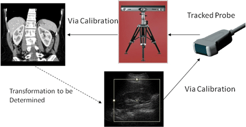
The conventional approach to US-CT registration is based on tracking the position of the US probe with a tracking system Citation[9–11] (). The ultrasound images are calibrated with respect to the US probe, which is tracked in space using, for example, infrared LEDs attached to the probe that are visible to a trinocular camera system Citation[10], while the CT images are calibrated with respect to the tracking system reference frame. The combination of calibrations and tracking enables the registration to be accomplished; however, errors are introduced in the two calibration steps and by the tracking device itself. In one study, registration errors were found to be 13 mm for landmarks inside the body during abdominal scanning Citation[11]. This approach requires a tracking system to be set up in the CT scanning area, which can be cumbersome and undesirable. Patient motion in the interval between the US and CT scans also introduces errors, although these might be mitigated by adding trackers to the patient.
A similar approach is used in EBRT for the treatment of prostate cancer. A BAT (B-mode Acquisition and Targeting) US system is used to acquire US images of the prostate Citation[3], Citation[12]. The US probe is attached to a positioning arm which tracks its 3D position. The arm is calibrated to a docking station for the machine, as is the CT scanner. The registration is performed using these calibrations and US probe positioning, similar to the external tracking case described above. Refinements to the registration are made manually by visually aligning the prostate boundaries. In a study of 35 patients Citation[3], this system gave prostate registration errors between the CT and US of up to 7.0 mm in the anterior/posterior direction, 6.4 mm in the lateral direction, and 6.7 mm in the superior/inferior direction. The combined multi-modality pre-operative registration and mono-modality intra-operative registration () has also been explored for EBRT with a mean target registration localization accuracy of 2.5 mm Citation[13].
In some cases, it may be possible to achieve registration by simply aligning the anatomical features in the CT and US images. Many such registration algorithms have been reported in the literature, including some specifically for US to CT registration. Brendel et al. Citation[14] registered CT and US datasets of the spine by matching surfaces and bone structures, with an accuracy of 0.5 mm. Maes et al. Citation[15] used mutual information to successfully register CT, MR and PET images with an accuracy of 1 mm; and Rusinek et al. Citation[16] aligned 3D brain scans (various modalities) using the centroid and principal axes of the brain, with an accuracy of 1–2 mm. Algorithms differ with respect to the amount of user interaction, the need for initialization, the speed of registration, the organ of interest, and the dimensions of the image data (i.e., 2D or 3D). Image-based, multi-modality registration is a difficult problem, especially if it is required to operate reliably on a wide range of patients in a clinical setting, and research in this area is therefore ongoing.
Many feature-based registration methods require initialization to work effectively. Iterative Closest Point (ICP) is a well-known algorithm used to match point clouds extracted from 3D images Citation[17], and its use in medical image registration has been widely reported Citation[18]. Initialization with an approximate alignment is required to ensure that the true optimum is reached since it is an iterative procedure and susceptible to local minima. A similar but more robust algorithm is the Covariance Matrix Adaptation Evolution Strategy (CMA-ES), which finds the true optimum more reliably, though at the expense of increased computational cost Citation[19]. Again, initialization of the registration is useful. Capture ranges (i.e., the required accuracy of the initialization) can vary for iterative methods. ICP works well with less than 30° and 30 mm of misalignment Citation[20]. Another example, which used simulated US images to register CT and US (via CMA-ES), required 15 mm or less of initial misalignment for the algorithm to work reliably Citation[21]. In a third example, where US datasets were registered using mutual information, the capture range was 24–44 mm Citation[22]. The capture range and registration accuracy depend on many factors, including the complexity of the surface shape, errors in surface localization, and the registration algorithm.
Some systems use a marker- or tracker-based registration to initialize the subsequent registration procedure. One example is the registration of bone surfaces between pre-operative CT and intra-operative US Citation[23]. The registration is initialized using anatomical landmarks (which are easily determined with bone structures), and ICP is used to fine-tune the registration. In another example, tracked US is used to initialize a feature-based approach which uses simulated US images Citation[24]. Such a combination may be necessary to account for organ motion due to breathing which is difficult to estimate with external trackers. In such cases, the errors in the tracker-based registration are acceptable so long as they fall within the capture range of the subsequent feature-based registration. This has motivated research into simpler methods of providing rigid-body US-to-CT registration which can be used to initialize feature-based registrations.
Proposed registration approach
A novel fiducial stand-off pad is proposed that will directly register 3D CT and 3D US volumes with a rigid-body transformation. In the proposed paradigm, a stand-off pad containing fiducial markers visible in CT and US is attached to the patient during pre-operative scanning. These fiducial markers will be aligned between the two image sets to perform the registration. The use of fiducials to register US and CT is, of course, not new: Lewis et al. demonstrated ultrasound detection of fiducials for surgical navigation more than a decade ago Citation[25]. The proposed technique takes this concept and applies it to a single re-usable stand-off pad which places fiducials in the near field of a 3D US transducer. This method is suitable for 3D US transducers, which have gained popularity in recent years, by allowing registration with a single acquisition of 3D US and CT data volumes.
The accuracy of this registration technique depends mainly on how well the fiducials can be localized in the 3D US volume. In contrast to previous research studies, the fiducials are placed in the near field of the US beam, which may affect the level of localization error. When traditional array transducers are used the US beam is narrowest at the focal depth and wider in the near and far fields (). That is, resolution in the lateral and elevational directions varies with depth. Although the focal point can be moved closer to the near field, there is a compromise between improving the image quality of the fiducials and maintaining the image quality of the organ of interest. Multiple transmit focal points can be used to maximize image quality in both near and far fields at the cost of decreased imaging speed. Our group has undertaken some preliminary work on localizing near-field fiducials, in which this approach was applied to calibration of tracked US, as opposed to CT-US registration Citation[26].
Materials and methods
Stand-off pad construction
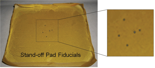
Polyvinyl chloride (PVC) was chosen as the pad material because it is durable, flexible and produces low attenuation of US. The soft plastic was heated to 180°C in a beaker while being stirred with a magnetic stir rod. When transparent, it was poured into a mold and allowed to cool. A layer of PVC was thus created, and fiducial markers were placed on this layer. A thin layer (2–3 mm) of PVC was then poured over the fiducial markers to seal them inside the pad. To simplify matching fiducials between the CT and US data, the pad contained only five metal spheres (1 mm in diameter) as fiducial markers (). Three fiducials (not collinear) are the minimum requirement for registration of two 3D volumes (CT and US). The two additional fiducials provide improved registration accuracy and allow for some undetected fiducials in the US data. Two of the five fiducials are placed close together, making the fiducial pattern obviously asymmetric to allow corresponding fiducials in each modality to be easily determined. The prototype pad contained some unavoidable defects (e.g., small air bubbles) that could potentially appear as fiducials when analyzing the images. The pad was enclosed in a latex-free US cover (Soft PullUp Ultrasound Probe Cover Kit, GE Healthcare, Waukesha, WI) to prevent contact between the PVC and the patient's skin. Ultrasound coupling gel was included inside the cover to prevent an air barrier forming between the pad and cover.
Two stand-off pads, with thicknesses of 12 mm and 20 mm, were constructed. A thinner pad should have less effect on image quality, but thicknesses of less than 12 mm were difficult to fabricate. A thicker stand-off pad enables improved visualization of the fiducials, since they are moved closer to the focal point, but also causes additional attenuation leading to degraded image quality for the organ of interest. The suitable stand-off pad thickness was selected by comparing the effect of each pad on images of a general-purpose multi-tissue US phantom (Computer Imaging Reference Systems, Inc., Norfolk, VA). The image quality (axial/lateral/elevational resolution and contrast) of the phantom features was compared with and without each of the constructed pads. Lateral and axial resolutions were found using the width and height of 9 point features in the phantom. The elevational resolution was found by taking US scans of the same 9 point features such that they appear as lines (i.e., images are perpendicular to the images used for lateral/axial resolution). The blurring of the line features was measured in the reconstructed US volume for each test case to obtain the elevational resolution change. Contrast ratios were computed based on the appearance of three occlusion features in the phantom.
Testing apparatus and procedure
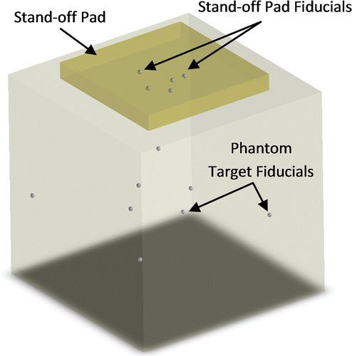
A designated testing phantom was used to obtain measures of fiducial localization error (FLE), fiducial registration error (FRE), and target registration error (TRE). The phantom () contained a layer of 9 phantom target fiducials (1 mm in diameter) located approximately 6 cm below the top surface. The phantom was made of agar gel (by mass, 1.17% high gel-strength agar, 4% glycerol, 0.25% bleach, and 94.58% water), wherein the amount of glycerol was chosen so that the speed of sound in the agar was 1540 m/s. The fiducial stand-off pad was secured to the top of the phantom during testing, with a layer of ultrasound coupling gel between the pad and phantom. Pressure was applied by the transducer to the pad near the fiducial locations to ensure good contact between the stand-off pad and the phantom.
Figure 5. Schematic of testing phantom containing phantom target fiducials (fiducial stand-off pad is secured to top).
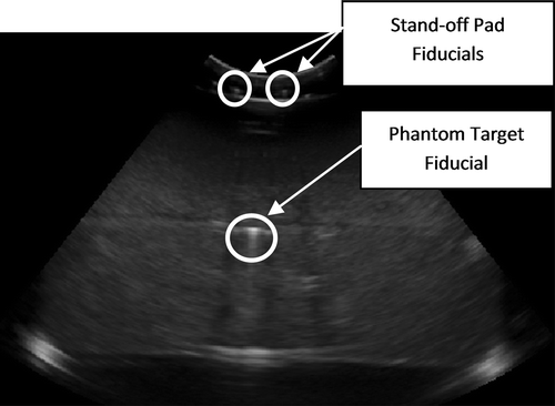
A 3D CT volume scan was obtained of the testing phantom with the fiducial stand-off pad secured to the top. Next, 3D US volumes of the phantom were obtained. Sample images from the US and CT scans are shown in and . The pad was not moved between the CT and the US scans. The US parameters of frequency, focal depth, gain and depth were varied to verify any significant effects on the FLE, FRE and TRE. The Sonix MDP ultrasound system (Ultrasonix Medical Corporation, Richmond, British Columbia, Canada) and a 4DC7-3/40 transducer were used to acquire the US volume data. Seventy-six frames per volume were obtained, with a field of view of 55°. Ultrasound scans were obtained for each of the parameter sets given in .
Figure 7. Sample CT image showing one phantom fiducial and one stand-off pad fiducial. The curved appearance of the stand-off pad is due to the coupling gel between the pad and phantom.
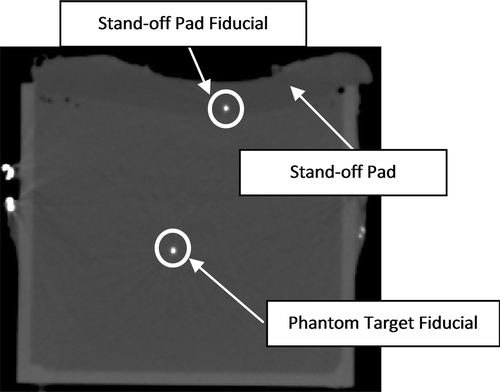
Table I. Ultrasound scanning parameter sets. Volumes contained 76 frames (55° sweep).
Ultrasound to CT registration
For the phantom study, the centers of the stand-off pad fiducials were manually selected in both CT and US images, using ITK-Snap software (University of Pennsylvania, Philadelphia, PA). These points were used to calculate rigid registration parameters by using the method of Horn et al. Citation[27]. The locations of the phantom target fiducials were also manually selected, and their positions recorded in CT and US; these were then used to calculate the TRE.
Four stand-off pad fiducials were used to calculate the rigid registration parameters, which were then used to calculate the FRE and TRE. The FRE was found by comparing the difference between the 3D positions of the stand-off pad fiducials in the US volume with their positions in the registered CT volume. The TRE was calculated by comparing the locations of 8 phantom target fiducials in the US volumes and in the registered CT volumes. Absolute errors (mean and standard deviation) in each principal direction are reported using all datasets (). RMS errors are used to demonstrate the effect of US parameters on the FRE and TRE.
A measure of the FLE was calculated using inter-fiducial distances. The distance between each of the stand-off pad fiducials was compared between the CT and US data to give a measure of how well the stand-off pad fiducials can be localized in the lateral and elevational directions of the probe. The distances between each stand-off pad fiducial and all phantom target fiducials were also compared between CT and US to give a measure of how well the fiducials can be localized in the axial direction. In both cases, the distances as found in CT were used as the gold standard. The average absolute FLE values (mean and standard deviation) in the two cases were computed using all of the collected measurements across all US parameter sets.
A clinical study (n = 3) was undertaken at Vancouver General Hospital after approval by the Clinical Research and Ethics Board (Certificate H08-02798). Subjects were recruited using signed consent from a list of patients scheduled for nephrectomy surgery. There were no exclusion criteria for subject participation. CT and US image data for a patient's kidney were registered in the same way as in the phantom study. The CT and US volumes were obtained with the stand-off pad secured to the patient and with the patient in the flank position. Each patient was requested to hold their breath on inspiration during both the CT and US scans to minimize respiratory movement of the kidney. The centroids of the fiducials were located using Stradwin 3.8 software Citation[28], and the rigid registration parameters were calculated as in the phantom study. Either 4 or 5 stand-off pad fiducials were used for registration depending on how many fell in the US field of view. Overlays were created by manually segmenting the kidney in both CT and US data. The segmented volumes were read into MATLAB (Mathworks, Natick, MA) and the CT volumes were transformed using the rigid registration transformation. The resulting volume overlays were plotted, again using MATLAB. The quality of the registration was assessed by viewing alignment of the renal structures in the overlays of the US and CT data after registration. The TRE was determined by measuring the distance between the centroids of the segmented kidneys as found in US and in registered CT data.
Computation of lever arm effect
Because the stand-off pad fiducials are located at the top of the image volumes that are to be registered, a small angular error in the registration of the fiducials could potentially result in a large registration error at the phantom target fiducials or at the kidney ().
Figure 8. Demonstration of the lever arm effect. White fiducials represent the true locations, and black fiducials represent locations with localization error. A small misalignment of the stand-off pad fiducials can result in large target registration errors.
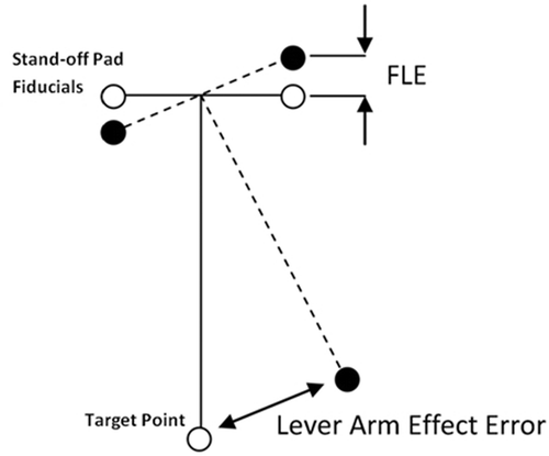
To calculate the magnitude of the lever arm effect, a worst-case scenario was used in which the localization error of each stand-off pad fiducial is always at a maximum.
It is assumed that the true position of the fiducials can be found in the CT scans. Using these locations, a plane of best fit was formed using the fiducial locations. A target point was located at the centroid of the fiducials and displaced some distance perpendicular to the plane (to simulate a target below the fiducials in the middle of an image). Displacements of 60 mm were used to simulate the conditions of the phantom study, and displacements of 80 mm to simulate the conditions of the clinical study. Each fiducial was perturbed from its true position by the maximum FLE. Essentially, an error cube was created around each fiducial location, and the error was calculated for all cases of each fiducial being at a corner of the error cube. For each case, the new location of the target point was calculated. The displacement between the true target point and the perturbed target point was calculated as the lever arm effect error. This process was repeated for 8 perturbations of each fiducial, for a total of 32,768 possible combinations of FLEs.
To find the centroid (C) of the fiducials, the fiducial locations P1, P2, P3, P4 and P5 were averaged. A plane of best fit was then found using these fiducial locations, and the unit normal (n) of the plane determined. The target point T was found by multiplying the distance (L = 60 mm or L = 80 mm) by the normal vector n and adding this to the centroid coordinates C (i.e., T = C + Ln). The fiducials were then perturbed by the maximum FLE and the calculation repeated with new coordinates for each fiducial location.
Results and discussion
Image quality results
A comparison of the lateral blurring, axial blurring, and image contrast is shown in , with the numerical results shown in –. The elevational blurring was found from reconstructed volumes, with a sample frame of one volume frame being shown in . For resolution, the 12-mm pad showed 11% degradation axially, 13% laterally, and 6% elevationally, compared to the case with no pad. The 20-mm pad showed more significant deterioration in axial and lateral resolution, with 32% degradation axially and 29% laterally. The elevational direction showed 7% degradation, similar to the 12-mm pad. The elevational resolution was limited mainly by the frame spacing in the US volume rather than the presence of the pad. The contrast degraded slightly, with 5% degradation in the case of the 12-mm pad and 6% degradation for the 20-mm pad when compared to the case with no pad. The stand-off pad fiducials could be seen without difficulty in both cases. Based on these results, the thinner 12-mm pad was chosen for phantom and clinical testing.
Figure 9. The CIRS quality assurance phantom with no stand-off pad (left), with a 12-mm thick stand-off pad (center), and with a 20-mm thick stand-off pad (right). Ultrasound acquisition settings were as follows: probe frequency 5 MHz; focal depth 7.6 cm; depth 15 cm; gain 48%. The arrows show the point feature target number 1, with numbers 2 to 9 below it in sequence, as in . The circles show the occlusion feature number 1, with numbers 2 and 3 diagonally below it in sequence, as indicated in .

Figure 10. Sample image of line features used to determine the degradation of resolution in the elevational direction. The arrow shows line feature target number 1, with numbers 2 to 9 below it in sequence (as in ).
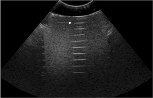
Table II. Effect of stand-off pad thickness on image quality. Ultrasound acquisition settings were as follows: frequency 5 MHz; focal depth 7.6 cm; depth 15 cm; gain 48%. There were 76 frames/volume (55° sweep). Point feature numbering is indicated in .
Table III. Effect of stand-off pad thickness on elevational resolution. Ultrasound acquisition settings were as follows: frequency 5 MHz; focal depth 7.6 cm; depth 15 cm; gain 48%. There were 76 frames/volume (55° sweep). Point feature numbering is indicated in .
Table IV. Effect of stand-off pad thickness on image contrast. Ultrasound acquisition settings were as follows: frequency 5 MHz; focal depth 7.6 cm; depth 15 cm; gain 48%. Occlusion feature numbering is indicated in .
Fiducial Localization Error (FLE)
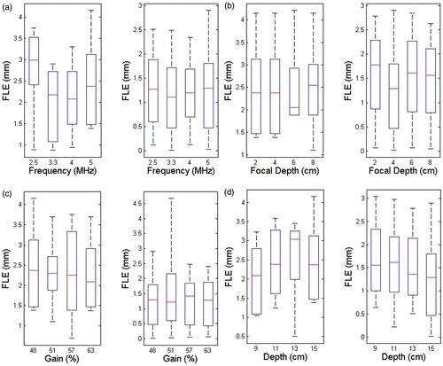
The box and whisker plots in show the minimum, maximum, median and 25th/75th percentiles of the error measurement data. For the FLE computed using the distance between pad fiducials (lateral and elevational FLE), the discrepancy was 2.38 ± 0.93 mm between the US and CT distance measurements. For the FLE computed using the distance between the pad and phantom fiducials (axial FLE), the discrepancy was 1.34 ± 0.80 mm between the US and CT distance measurements. As expected, axial components of the FLE were smaller than the lateral and elevational components. There was no strong dependence of the FLE on the US parameters used.
Figure 11. FLE vs. various ultrasound parameters (see ). In each panel, the left graph shows errors in measurements of distances between stand-off pad fiducials (N = 6) indicating lateral and elevational errors, and the right graph shows errors in measurement of distances between the stand-off pad and phantom target fiducials (N = 32) indicating axial errors. (a) FLE vs. probe frequency; (b) FLE vs. focal depth; (c) FLE vs. gain; and (d) FLE vs. depth.
Registration error results: phantom study (FRE and TRE)
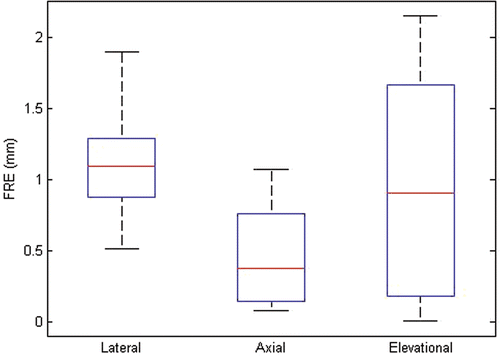
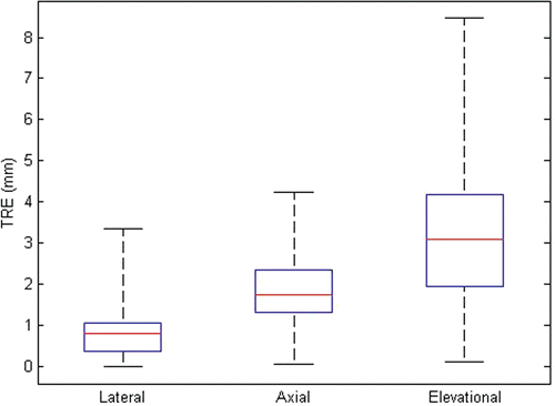
The RMS errors for registration as affected by the various US parameters are shown in (FRE) and (TRE), and the box and whisker plots in and show the minimum, maximum, median and 25th/75th percentiles of the FRE and TRE in each principal direction.
Figure 12. RMS FRE vs. various ultrasound parameters. (a) FRE vs. probe frequency (focal depth 4 cm; gain 48%; depth 15 cm). (b) FRE vs. focal depth (frequency 5 MHz; gain 48%; depth 15 cm). (c) FRE vs. gain (frequency 5 MHz; focal depth 4 cm; depth 15 cm). (d) FRE vs. depth (frequency 5 MHz; focal depth 4 cm; gain 48%).
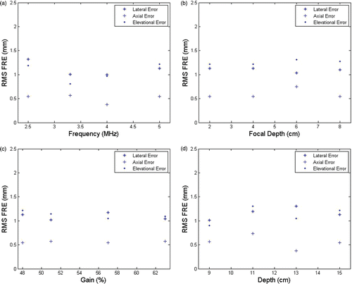
Figure 14. RMS TRE vs. various ultrasound parameters. (a) TRE vs. probe frequency (focal depth 4 cm; gain 48%; depth 15 cm). (b) TRE vs. focal depth (probe frequency 5 MHz; gain 48%; depth 15 cm). (c) TRE vs. gain (probe frequency 5 MHz; focal depth 4 cm; depth 15 cm). (d) TRE vs. depth (probe frequency 5 MHz; focal depth 4 cm; gain 48%).
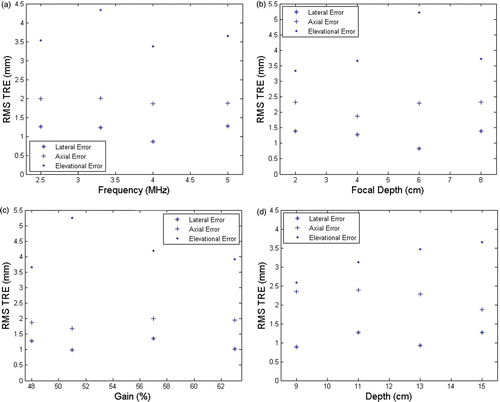
There was no strong dependence of the FRE and TRE on the different US parameters used. The absolute FRE was 1.08 ± 0.29 mm in the lateral direction, 0.46 ± 0.33 mm in the axial direction, and 0.90 ± 0.71 mm in the elevational direction. The absolute TRE was 0.89 ± 0.76 mm in the lateral direction, 1.84 ± 0.95 mm in the axial direction, and 3.31 ± 1.97 mm in the elevational direction. As expected, the FRE was smaller in the axial direction than in the lateral and elevational directions. The TRE was smallest in the lateral direction. A small amount of reverberation seen on phantom target fiducials in the axial direction resulted in slightly higher axial errors.
Registration error results: clinical study (FRE and TRE)
shows sample images of the CT and US data that were registered using the stand-off pad. The FRE for the registration of three patient datasets is given in , with values similar to those found in the phantom study. Overlays of the registered CT data and the US data are shown in .
Figure 16. Sample CT (left) and ultrasound (right) images of patient's kidney with stand-off pad attached. Ultrasound acquisition settings were as follows: frequency 5 MHz; focal depth 7.6 cm; gain 42%; depth 13 cm.
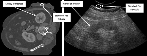
Figure 17. Overlays of clinical data for three patients after registration using the fiducial stand-off pad. CT data is shown in blue and ultrasound data in red. (a) Patient 1; (b) Patient 2; (c) Patient 3.
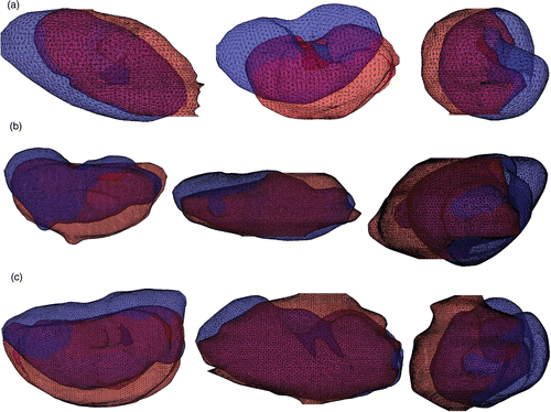
Table V. RMS FRE for clinical data from three patients.
This initial registration of clinical data had larger registration errors than seen in the phantom study, as summarized in . The registration error was 18.72 mm for the first patient, 11.81 mm for the second and 11.59 mm for the third. The errors were composed of 1–15 mm error in the lateral direction, 8–12 mm error in the axial direction, and 1–3 mm error in the elevational direction.
Table VI. TRE for clinical data from three patients.
Computation of lever arm effect
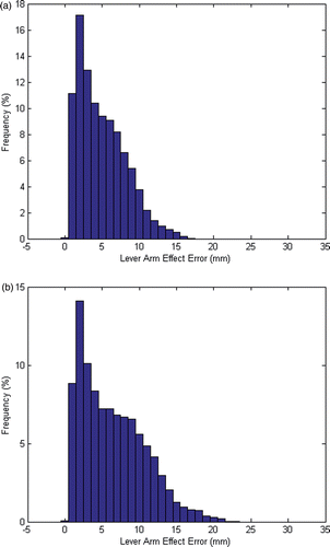
Using the formulation presented earlier, the errors arising from the lever arm effect were computed. For the phantom study (), the mean lever arm error was 4.96 mm and the maximum was 17.16 mm. For the clinical study (), the mean error was 6.42 mm and the maximum was 22.72 mm. The histograms in show the error distribution for all tested perturbations, indicating the low frequency of the maximum error. Furthermore, the calculations assume that all fiducials are always located with maximum FLE, which would not be the case in actual trials. Therefore, these calculated errors are higher than we expect to see in the actual registration results.
Further discussion
In this study, the stand-off pad fiducials were clearly visible in both CT and US images. In US images, the fiducials were easily distinguished from the unavoidable defects (air bubbles) in the pad. The stand-off pad had a curved appearance in CT images (), despite being flat in its construction. This was due to the ultrasound coupling gel between the pad and the phantom which was displaced to the sides of the pad when pressure was applied to the stand-off pad by the US transducer (see Testing apparatus and procedure sub-section). The decrease in resolution and contrast (–) did not hinder our ability to see the phantom target fiducials (controlled study) or the kidney boundary (clinical study). Further optimization of the pad and fiducial construction using techniques from commercial stand-off pad construction could reduce these errors. The concern that the stand-off pad fiducials would obscure anatomy through acoustic shadowing did not materialize in these tests.
The measurement of FLE (shown in ) is meant to give an indication of how accurately the true position of the fiducials can be determined. The higher error in the lateral/elevational direction is caused by the round fiducials appearing oblong in the US volumes (due to the large elevational width of the US beam at this depth). The axial direction had lower FLE, as expected, since the axial resolution of US is better than the elevational and lateral resolutions. The methodology used is expected to overestimate the FLE because it does not measure the FLE of each fiducial independently. Rather, two fiducials affect each single error measurement. A lower real FLE would also result in calculation of smaller lever arm errors as described above.
The measurement of FRE gives an indication of how well the fiducials can be aligned between the US and CT data. The phantom study RMS FRE results () are consistent across the various US parameter sets. This intuitively follows the fact that the fiducial localization is not affected by the variation in the parameters.
The measurement of TRE gives an indication of how well the target is aligned in the body when the registration is performed using fiducials in the pad near the skin surface. The phantom study RMS TRE results () are also consistent across the various US parameter sets. In this case, the lateral direction has the smallest TRE values. The slight degradation of the axial error resulted from a small axial reverberation in the phantom fiducial images, making the axial location of the phantom fiducials more difficult to determine than for the stand-off pad fiducials. The main source of error in the phantom study was the lever arm effect, which is related to the FLE.
The results for clinical data are shown for three patients in and . The FRE for the patient data is similar to the FRE for the phantom data. FRE is least in the axial direction and greatest in the elevational direction. Similar FRE between phantom and patients is to be expected because the registration is based on the appearance of the fiducials in the pad, which is unaffected by the underlying anatomy. shows that a small FRE does not necessarily correspond to small errors in alignment of the kidney boundaries. provides quantification of these registration errors. Misalignment of kidney surfaces was probably due to respiration-induced organ motion relative to the skin and stand-off pad in the interval between the CT and US scans, as well as to some tissue compression due to US probe pressure.
A large portion of the lateral error is a result of respiratory motion of the kidney. A breath-hold was requested (after inspiration) during the CT and US scans, but consistency of the breath-hold is essential. Traditional US-CT alignment methods based on trackers suffer from similar errors due to respiration. For example, the registration approach of Kaspersen et al. Citation[11] produced a similar average amount of error (13 mm). Moerland et al. Citation[29] found that the kidney moves between 10 and 86 mm under forced respiration (with the patient in the supine position), and a similar study by Schwartz et al. Citation[30] showed movement of 4–43 mm for deep respiration (with the patient in the supine position). Thus, the amount of kidney movement possible because of an inconsistent breath-hold is significant. The simplest method of reducing motion from respiration is to have the patient perform a breath-hold during the CT and US scans, but this may not be practical. Alternatively, a respiratory belt transducer could be used to synchronize image acquisition with a particular respiratory stage, e.g., full expiration. Other solutions, such as predictive respiration gating Citation[31], could also be used.
A portion of the axial error may also be caused by the tissue compression when under pressure from the US probe. Comparison of the skin-to-kidney distance distances in the CT and US data showed a difference of 8 mm for the first subject, 10 mm for the second and 10 mm for the third. These preliminary results suggest that probe pressure should be minimized during scanning to reduce this source of error. It may also be possible to compensate for probe compression errors by using the skin-to-organ distance as a measure of probe pressure and adjusting the alignment accordingly. The underlying assumption of this fiducial-based approach is that the kidney does not move with respect to the fiducials, making it sensitive to respiratory motion of the kidney and to motion of the fiducials on the skin resulting from probe pressure. The tracked US approaches assume that the kidney alone does not move, meaning there is little sensitivity to motion of the skin resulting from compression by the probe.
The results for the magnitude of the lever arm effect indicate that this was the main cause of registration errors in the controlled phantom study. It is interesting to note that the lever arm effect was not seen significantly in the clinical data. The major misalignment was consistently along the long axis of the kidney, and along the axial direction. If a lever arm effect were the main cause, we would expect to see more variation in the major direction of the error, since the stand-off pad is placed in different orientations for different patients, and the lever arm effect is not limited to a single direction. Lever arm effect could be reduced by using more fiducials in the stand-off pad for the registration.
In summary, the fiducial stand-off pad can produce 0.89 to 3.3 mm of TRE between ultrasound and CT datasets of phantoms with low-cost, simple and physically robust apparatus. The trade-off is a small reduction in image quality that might be mitigated with improved construction of the stand-off pad. Preliminary clinical results suggest that the pad provided similar FRE to that obtained in the phantom study, but alignment of the organ boundaries is still affected by tissue deformation, especially from respiration. As such, this approach is suitable for an initialization of image-based registration methods, such as those described in references Citation[17], Citation[19], Citation[21], Citation[22], for which the 12–18 mm of misalignment () fits within the capture range. This is a small sampling of possible feature-based methods that can be initialized with the fiducial stand-off pad, and future work will focus on using the pad for initialization of deformable feature-based registrations of the kidney in CT and 3D ultrasound datasets.
Acknowledgements
The authors thank Dr. Septimiu Salcudean for providing additional advice and expertise. Caitlin Schneider, Jing Xiang, John Bartlett and Michael Yip are thanked for their role in obtaining clinical data for this study. Canada Diagnostics is thanked for their technical support in providing CT scanning for the phantom-based study.
Declaration of Interest: This work was supported by the National Science and Engineering Research Council of Canada. The authors have no interests to declare.
References
- Gobbi DG, Comeau RM, Peters TM, Ultrasound/MRI overlay with image warping for neurosurgery. In: Delp SL, DiGioia AM, Jaramaz B, editors. Proceedings of the Third International Conference on Medical Image Computing and Computer Assisted Intervention (MICCAI 2000), Pittsburgh, PA, October 2000. Lecture Notes in Computer Science 1935. Berlin: Springer; 2000. pp 106–114
- Ma B, Ellis RE. Robust registration for computer-integrated orthopedic surgery: Laboratory validation and clinical experience. Med Image Anal 2003; 7(3)237–250
- Lattanzi J, McNeely S, Hanlon A, Schultheiss TE, Hanks GE. Ultrasound-based stereotactic guidance of precision conformal external beam radiation therapy in clinically localized prostate cancer. Urology 2000; 55(1)73–78
- Blake CC, Elliot TL, Slomka PJ, Downey DB, Fenster A. Variability and accuracy of measurements of prostate brachytherapy seed position in vitro using three-dimensional ultrasound: An intra- and inter-observer study. Med Phys 2000; 27(12)2788–2795
- Boctor EM, Fichtinger G, Taylor RH, Choti MA. Tracked 3D ultrasound in radio-frequency liver ablation. Proc SPIE Med Imaging 2003; 5035: 174–182
- Kaul S, Laungani R, Sarle R, Stricker H, Peabody J, Littleton R, Menon M. da Vinci-assisted robotic partial nephrectomy: Technique and results at a mean of 15 months of follow-up. Eur Urol 2007; 51(1)186–191
- Finelli A, Gill IS. Laparoscopic partial nephrectomy: Contemporary technique and results. Urol Oncol 2004; 22: 139–144
- Link RE, Bhayani SB, Allaf ME, Varkarakis I, Inagaki T, Rogers C, Su L-M, Jarrett TW, Kavoussi LR. Exploring the learning curve, pathological outcomes and perioperative morbidity of laparoscopic partial nephrectomy performed for renal mass. J Urol 2005; 173: 1690–1694
- Comeau RM, Sadikot AF, Fenster A, Peters TM. Intraoperative ultrasound for guidance and tissue shift correction in image-guided neurosurgery. Med Phys 2000; 27(4)787–800
- Trobaugh JW, Richard WD, Smith KR, Bucholz RD. Frameless stereotactic ultrasonography: Method and applications. Computerized Medical Imaging and Graphics 1994; 18(4)235–246
- Kaspersen JH, Sjolie E, Wesche J, Asland J, Lundbom J, Odegard A, Lindseth F, Nagelhus Hernes TA. Three-dimensional ultrasound-based navigation combined with preoperative CT during abdominal interventions: A feasibility study. Cardovasc Intervent Radiol 2003; 26: 347–356
- Chandra A, Dong L, Huang E, Kuban DA, O’Neill L, Rosen I, Pollack A. Experience of ultrasound-based daily prostate localization. Int J Radiat Oncol Biol Phys 2003; 56(2)436–447
- Wang M, Rohling R, Duzenli C, Clark B, Archip N. Evaluation of targeting errors in ultrasound-assisted radiotherapy. Ultrasound Med Biol 2008; 34(12)1944–1956
- Brendel B, Winter S, Rick A, Stockheim M, Ermert H. Registration of 3D CT and ultrasound datasets of the spine using bone structures. Comput Aided Surg 2002; 7: 146–155
- Maes F, Collignon A, Vandermeulen D, Marchal G, Suetens P. Multimodality image registration by maximization of mutual information. IEEE Trans Med Imaging 1997; 16(2)187–198
- Rusinek H, Tsui W-H, Levy AV, Noz ME, de Leon MJ. Principal axes and surface fitting methods for three-dimensional image registration. J Nucl Med 1993; 34: 2019–2024
- Besl PJ, McKay ND. A method for registration of 3D shapes. IEEE Trans Pattern Anal Machine Intell 1992; 14(2)239–256
- Hill DLG, Batchelor PG, Holden M, Hawkes DJ. Medical image registration. Phys Med Biol 2001; 46: R1–R45
- Hansen N, Muller SD, Koumoutsakos P. Reducing the time complexity of the derandomized evolution strategy with covariance matrix adaptation (CMA-ES). Evolutionary Computation 2003; 11(1)1–18
- Wilson K, Guiraudon G, Jones D, Peters TM, 4D shape registration for dynamic electrophysiological cardiac mapping. In: Larsen R, Nielsen M, Sporring J, editors. Proceedings of the 9th International Conference on Medical Image Computing and Computer-Assisted Intervention (MICCAI 2006), Copenhagen, Denmark, October 2006. Part II. Lecture Notes in Computer Science 4191. Berlin: Springer; 2006. pp 520–527
- Xiang J, Registration of 3D ultrasound to computed tomography images of the kidney. MASc thesis, Department of Electrical and Computer Engineering, University of British Columbia, Vancouver, British Columbia, Canada, 2010
- Shekhar R, Zagrodsky V. Mutual information-based rigid and non-rigid registration of ultrasound volumes. IEEE Trans Med Imaging 2002; 21(1)9–22
- Amin DV, Kanade T, DiGioia AM, Jaramaz B. Ultrasound registration of the bone surface for surgical navigation. Comput Aided Surg 2003; 8: 1–16
- Wein W, Röper B, Navab N, Automatic registration and fusion of ultrasound with CT for radiotherapy. In: Duncan JS, Gerig G, editors. Proceedings of the 8th International Conference on Medical Image Computing and Computer-Assisted Intervention (MICCAI 2005), Palm Springs, CA, October 2005. Part II. Lecture Notes in Computer Science 3750. Berlin: Springer; 2005. pp 303-311
- Lewis JT, Galloway RI, Jr, Schreiner S. An ultrasonic approach to localization of fiducial markers for interactive, image-guided neurosurgery. I. Principles. IEEE Trans Biomed Eng 1998; 45(5)620–630
- Poon TC, Rohling RN. Tracking a 3D ultrasound probe with constantly visible fiducials. Ultrasound Med Biol 2007; 33(1)152–157
- Horn BK, Hilden HM, Negahdaripour S. Closed form solution of absolute orientation using unit quaternions. J Optical Soc Am 1987; 4: 629–642
- Treece GM, Prager RW, Gee AH, Berman L. Surface interpolation from sparse cross-sections using region correspondence. IEEE Trans Med Imaging 2000; 19(11)1106–1114
- Moerland MA, van den Bergh ACM, Bhagwandien R, Janssen WM, Bakker CJG, Lagendijk JJW, Battermann JJ. The influence of respiration induced motion of the kidneys on the accuracy of radiotherapy treatment planning, a magnetic resonance imaging study. Radiother Oncol 1994; 30: 150–154
- Schwartz LH, Richaud J, Buffat L, Touboul E, Schlienger M. Kidney mobility during respiration. Radiother Oncol 1994; 32: 84–86
- Ritchie CJ, Hsieh J, Gard MF, Godwin JD. Predictive respiratory gating: A new method to reduce motion artifacts on CT scan. Radiology 1994; 190: 847–852

