Abstract
Objective: The aim of this study was to evaluate the accuracy of a novel 3-dimensional (3D) fluoroscopic navigation system using a flat-panel detector-equipped C-arm, focusing on the influence of the distance from the center of fluoroscopic imaging on navigation accuracy.
Materials and Methods: A geometric phantom was made using a Styrofoam cube with 25 markers, each consisting of a metal ball 1.5 mm in diameter, fixed in a cross arrangement at 1-cm intervals. Hip joint surgery was simulated using a set of dry pelvic and femoral bones. A total of eight markers were fixed to the acetabulum and proximal femur.
Results: In the geometric phantom study, mean target registration error (TRE) was 0.7 mm (range: 0.1–1.5). The TRE of markers located at 5 cm from the imaging center was significantly higher than the TRE of markers located at 1 and 2 cm. However, the TRE was <1 mm in 90% of the overall trials and <1.5 mm in 100%. In the dry bone study, the mean TRE was 0.9 mm (range: 0.7–1.5) over the acetabulum and 1.0 mm (range: 0.5–1.4) over the femur. No significant difference in TRE was seen between the acetabulum and proximal femur.
Conclusion: The accuracy of this novel 3D fluoroscopic navigation system was considered acceptable for clinical application. A 3D C-arm equipped with a flat-panel detector could increase the feasibility of 3D fluoroscopic navigation by reducing the effects of image distortion on navigation accuracy.
Introduction
Three-dimensional (3D) fluoroscopic navigation systems using Iso-C3D, a mobile 3D C-arm equipped with an image intensifier, have been successfully validated for surgeries of the cervical Citation[1–6], thoracic [3, 6-9] and lumbar [3, 6, 10-12] spine, sacrum Citation[6], Citation[13–15], pelvis Citation[16] and lower extremities Citation[17–19]. The quality of imaging is a crucial factor for safe performance of image-based navigation. A new 3D C-arm equipped with a flat-panel detector offers the advantages of flat-panel technology for intraoperative 3D imaging, significantly improving image quality and eliminating the image distortion near the edges of the scan that was inherent to the image intensifier-equipped C-arm Citation[20–21]. A mobile C-arm equipped with a flat-panel detector might therefore increase the feasibility of 3D fluoroscopic navigation in surgery. The aim of the present study was to evaluate the accuracy of a novel 3D fluoroscopic navigation system using the flat-panel detector-equipped C-arm, focusing on the influence of the distance from the center of fluoroscopic imaging on navigation accuracy.
Materials and methods
The navigated procedure was performed using a computer navigation system (Stryker Navigation System II Cart; Stryker, Kalamazoo, MI) and a mobile 3D C-arm with a flat-panel detector (Ziehm Vision FD Vario 3D; Ziehm Imaging, Nuremberg, Germany). Prior to the procedure, two directional C-arm images were obtained to ensure that the scanned volume was correctly centered over the subject. The C-arm was connected to the navigation system and calibrated by registering three points on the detector using a pointing device. Subsequently, 110 single images from a right cylindrical volume of diameter 12 cm and height 12 cm were acquired during a 60-second automated orbital scan of 135°.
To assess whether the distance from the center of fluoroscopic imaging affects navigation accuracy, we created a geometric phantom using a cube of Styrofoam onto which 25 fiducial markers were fixed on a plane in a cross arrangement at intervals of 1 cm (). The Cranial Marker Set (Stryker Leibinger, Freiburg, Germany) was used, each marker consisting of a plastic male matrix pin with a gold ball (diameter 1.5 mm) inside that engages the female matrix, whose inner thread can be screwed to the additional outer thread of the head of a 2.0-mm titanium bone screw. In the geometric phantom, a component with a gold ball was used to avoid image artifacts due to titanium bone screws. The phantom was placed on a Styrofoam board corresponding to an operating table. The board was supported at a height of 1 meter from the floor by four tripods. The C-arm was placed on the left side of the table and the navigation system was placed at the caudal end (). Four sets of 3D fluoroscopic images were obtained with the plane of the phantom with markers affixed facing upward, caudal and lateral to the C-arm, and lateral to the opposite side of the C-arm. The tip of the navigation probe was directed at each marker. Virtual points were superimposed with the positions of metal marker images for subsequent measurements of accuracy. The tip of the navigation probe was then directed at each metal marker. The target navigation error was recorded and measured as the distance between the virtual tip of the navigation probe and the virtual points on the navigation display. These procedures were repeated three times.
Figure 1. (a) The geometric phantom was a Styrofoam cube with 25 fiducial markers, each consisting of a metal ball 1.5 mm in diameter, fixed in a cross arrangement at intervals of 1 cm. (b) A 2-dimensional image from the C-arm.
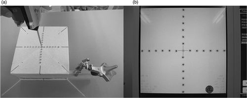
Figure 2. Experimental set-up of the geometric phantom study (a) and dry bone study (b). The C-arm was placed on the left side of the operation table and the navigation system was placed at the caudal end. In the geometric phantom study, the plane of the phantom with the markers affixed faced upward.
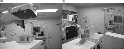
To simulate surgeries around the hip joint, a dry human pelvis and femur were placed on the operating table in the lateral decubitus position ( and ). Using titanium bone screws, a total of eight fiducial markers (Cranial Marker Set; Stryker Leibinger) were fixed to the following locations of the acetabulum and proximal femur: the anterior, posterior, superior and inferior acetabular edges; the tip of the great trochanter; the base of the lesser trochanter; the proximal head-neck junction; and the anterior cortex of the femoral neck (). Two dynamic reference trackers were fixed to the ipsilateral pelvic crest and femoral shaft. Navigation accuracy was evaluated using a similar method to that in the geometric phantom study. These procedures were also repeated three times.
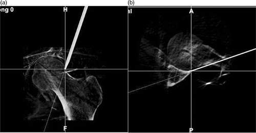
Figure 3. (a) Surgery around the hip joint was simulated with a dry human pelvis and femur placed on the operating table in the lateral decubitus position. (b) A 2-dimensional image from the C-arm.
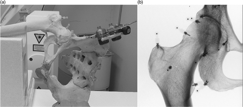
Visual assessment of navigation accuracy was also performed by directing the tip of the navigation probe at the landmarks where fiducial markers were inserted with the navigation probe. A match was accepted if the bony contours on the navigation display showed a difference of <1 mm on visual assessment, which was performed by two of the authors (M.T., K.Y.).
The influence of the distance of markers from the center on target registration error (TRE) was assessed using the Kruskal-Wallis test and the Dunn test; the TRE between the acetabulum and proximal femur was compared using the Mann-Whitney test. Statistical software (IBS SPSS Statistics 19; SPSS, Chicago, IL) was used for all statistical analyses. A 5% significance level was applied for all tests (p < 0.05).
Results
In the geometric phantom study, the mean TRE was 0.7 mm (range: 0.1–1.5 mm). The TRE of the novel 3D fluoroscopic navigation system was <1 mm in 90% of trials and <1.5 mm in 100% of trials. The distance of markers from the center did not affect TRE at distances up to 4 cm (). The TRE of markers located at 5 cm from the imaging center was significantly higher than TRE of markers located at 1 and 2 cm. However, the TRE of the markers located at 5 cm was <1 mm in 85% of trials and <1.5 mm in 100% of trials.
Figure 4. The TRE of markers located at 5 cm from the imaging center was higher than the TRE of markers located at 1 and 2 cm. TRE was <1 mm in 90% of the overall trials and <1.5 mm in 100%.
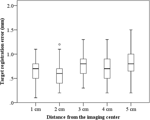
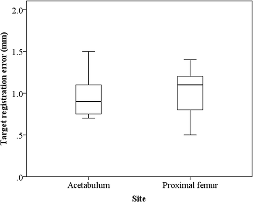
In the dry bone study, the mean TRE over the acetabulum was 0.9 mm (range: 0.7–1.5 mm), and the mean TRE over the proximal femur was 1.0 mm (range: 0.5–1.4 mm). No significant difference in TRE was seen between the acetabulum and proximal femur (). The TRE was <1 mm in 58% of trials and <1.5 mm in 100% of trials. Matching was accepted in all trials, with bony contours on the navigation display showing a difference of <1 mm (). The assessments by the two authors were in agreement for all trials.
Discussion
To date, applications of 3D fluoroscopic navigation systems using Iso-C3D have mainly been in screw insertion or in drilling into the cervical Citation[1–6], thoracic [3, 6-9] and lumbar [3, 6, 10-12] spine, sacrum Citation[6], Citation[13–15], pelvis Citation[16] and lower extremities Citation[17–19]. The flat-panel detector-equipped 3D C-arm, like the Iso-C3D, has a limited display window of approximately 12 cm. In some surgeries, performing screw insertion or drilling from the entry point to the target around the imaging center of a right cylindrical volume of diameter 12 cm and height 12 cm is difficult. Image distortion within the display window should thus significantly influence the accuracy of screw insertion and drilling using 3D fluoroscopic navigation. In this novel 3D fluoroscopic navigation system, the TRE of markers located 5 cm from the imaging center was higher than the TREs for markers located at 1 and 2 cm. However, the TRE of the markers located at 5 cm was <1 mm in 85% of trials and <1.5 mm in 100% of trials. We believe that this tolerance against image distortion could increase the feasibility of 3D fluoroscopic surgical navigation.
The dynamic reference tracker position has also been reported to affect navigation accuracy in 3D fluoroscopic navigation using Iso-C3D Citation[22]. Assessing navigation accuracy in an experimental set-up simulating real surgeries is thus important. We simulated surgeries around the hip joint by fixing the dynamic reference trackers in the iliac crest and femoral shaft. In the dry bone study, the mean TRE was <1 mm in 58% of trials and <1.5 mm in 100% of trials. We considered this level of accuracy to be acceptable for clinical applications.
A metal ball 1.5 mm in diameter was used to assess navigation accuracy, which represents one limitation of this study. The marker also gave rise to image artifacts inherent to the metal ball. Assessment of TRE at the sub-millimeter level was therefore difficult in this experiment. In terms of visual assessment, bony contours around the acetabulum and proximal femur on the navigation display were consistent with the real bony surface. This indicates that the navigation system might be more accurate than shown by the results for TRE in the present study.
In conclusion, the accuracy of this novel 3D fluoroscopic navigation system was considered acceptable for clinical applications. A 3D C-arm equipped with a flat-panel detector could increase the feasibility of 3D fluoroscopic navigation by reducing the effects of image distortion on navigation accuracy.
Declaration of interest: This study was supported by a Grant-in-Aid for Scientific Research (KAKENHI) from the Japan Society for the Promotion of Science [No. 22791377, Grant-in-Aid for Young Scientists (B)]. No benefits in any form have been received or will be received from a commercial party related directly or indirectly to the subject of this article.
Notes
Notice of correction: This paper published online on 2 August 2011 contained an error in the first affiliation. This has been corrected in the current version.
References
- Ito Y, Sugimoto Y, Tomioka M, Hasegawa Y, Nakago K, Yagata Y. Clinical accuracy of 3D fluoroscopy-assisted cervical pedicle screw insertion. J Neurosurg Spine 2008; 9: 450–453
- Laufer I, Greenfield JP, Anand VK, Hartl R, Schwartz TH. Endonasal endoscopic resection of the odontoid process in a nonachondroplastic dwarf with juvenile rheumatoid arthritis: feasibility of the approach and utility of the intraoperative Iso-C three-dimensional navigation. Case report. J Neurosurg Spine 2008; 8: 376–380
- Rajasekaran S, Kamath V, Shetty AP. Intraoperative Iso-C three-dimensional navigation in excision of spinal osteoid osteomas. Spine (Phila Pa 1976) 2008; 33: E25–E29
- Rajasekaran S, Vidyadhara S, Shetty AP. Iso-C3D fluoroscopy-based navigation in direct pedicle screw fixation of Hangman fracture: a case report. J Spinal Disord Tech 2007; 20: 616–619
- Hott JS, Papadopoulos SM, Theodore N, Dickman CA, Sonntag VK. Intraoperative Iso-C C-arm navigation in cervical spinal surgery: review of the first 52 cases. Spine (Phila Pa 1976) 2004; 29: 2856–2860
- Hott JS, Deshmukh VR, Klopfenstein JD, Sonntag VK, Dickman CA, Spetzler RF, Papadopoulos SM. Intraoperative Iso-C C-arm navigation in craniospinal surgery: the first 60 cases. Neurosurgery 2004; 54: 1131–1136, discussion 6-7
- Sugimoto Y, Ito Y, Tomioka M, Shimokawa T, Shiozaki Y, Mazaki T, Tanaka M. Clinical accuracy of three-dimensional fluoroscopy (IsoC-3D)-assisted upper thoracic pedicle screw insertion. Acta Med Okayama 2010; 64: 209–212
- Rajasekaran S, Vidyadhara S, Ramesh P, Shetty AP. Randomized clinical study to compare the accuracy of navigated and non-navigated thoracic pedicle screws in deformity correction surgeries. Spine (Phila Pa 1976) 2007; 32: E56–E64
- Hubbe U, Kogias E, Vougioukas VI. Image guided percutaneous trans-pedicular screw fixation of the thoracic spine. A clinical evaluation. Acta Neurochir (Wien) 2009; 151: 545–549, discussion 9
- Nakashima H, Sato K, Ando T, Inoh H, Nakamura H. Comparison of the percutaneous screw placement precision of isocentric C-arm 3-dimensional fluoroscopy-navigated pedicle screw implantation and conventional fluoroscopy method with minimally invasive surgery. J Spinal Disord Tech 2009; 22: 468–472
- Geerling J, Gosling T, Gosling A, Ortega G, Kendoff D, Citak M, Krettek C, Hüfner T. Navigated pedicle screw placement: experimental comparison between CT- and 3D fluoroscopy-based techniques. Comput Aided Surg 2008; 13: 157–166
- Acosta FL, Jr, Thompson TL, Campbell S, Weinstein PR, Ames CP. Use of intraoperative isocentric C-arm 3D fluoroscopy for sextant percutaneous pedicle screw placement: case report and review of the literature. Spine J 2005; 5: 339–343
- Briem D, Linhart W, Lehmann W, Begemann PG, Adam G, Schumacher U, Cullinane DM, Rueger JM, Windolf J. Computer-assisted screw insertion into the first sacral vertebra using a three-dimensional image intensifier: results of a controlled experimental investigation. Eur Spine J 2006; 15: 757–763
- Zwingmann J, Konrad G, Kotter E, Sudkamp NP, Oberst M. Computer-navigated iliosacral screw insertion reduces malposition rate and radiation exposure. Clin Orthop Relat Res 2009; 467: 1833–1838
- Smith HE, Yuan PS, Sasso R, Papadopolous S, Vaccaro AR. An evaluation of image-guided technologies in the placement of percutaneous iliosacral screws. Spine (Phila Pa 1976) 2006; 31: 234–238
- Ochs BG, Gonser C, Shiozawa T, Badke A, Weise K, Rolauffs B, Stuby FM. Computer-assisted periacetabular screw placement: Comparison of different fluoroscopy-based navigation procedures with conventional technique. Injury 2010; 41(12)1297–1305
- Rajasekaran S, Karthik K, Chandra VR, Rajkumar N, Dheenadhayalan J. Role of intraoperative 3D C-arm-based navigation in percutaneous excision of osteoid osteoma of long bones in children. J Pediatr Orthop B 2010; 19: 195–200
- Richter M, Zech S. Computer Assisted Surgery (CAS) guided arthrodesis of the foot and ankle: an analysis of accuracy in 100 cases. Foot Ankle Int 2008; 29: 1235–1242
- Citak M, Kendoff D, Kfuri M, Jr, Pearle A, Krettek C, Hüfner T. Accuracy analysis of Iso-C3D versus fluoroscopy-based navigated retrograde drilling of osteochondral lesions: a pilot study. J Bone Joint Surg Br 2007; 89: 323–326
- Kalender WA, Kyriakou Y. Flat-detector computed tomography (FD-CT). Eur Radiol 2007; 17: 2767–2779
- Reichardt B, Sarwar A, Bartling SH, Cheung A, Grasruck M, Leidecker C, Bredella MA, Brady TJ, Gupta R. Musculoskeletal applications of flat-panel volume CT. Skeletal Radiol 2008; 37: 1069–1076
- Citak M, Kendoff D, Wanich T, Pearle A, Singhai R, Krettek C, Hüfner T. The influence of distance on registration in ISO-C-3D navigation: a source of error in ISO-C-3D navigation. Technol Health Care 2006; 14: 473–478
