Abstract
Background: The entanglement of the otological drill with cotton swabs is a common milling fault in ear surgery. To improve operational safety, this paper presents a method for identifying this type of milling fault.
Methods: Force and current sensors were installed on a modified otological drill. In accordance with the DC motor model and cutting force model, two features of the milling process were extracted, namely the characteristic curve and the dynamic relationship between the sensor signals. These are complementary features. An adaptive filter was designed to fuse them together and output a curve that was sensitive to milling faults and was stable during normal milling. Based on the filtering data, a rule base is presented for identifying cotton swab entanglement.
Results: Five surgeons were invited to perform an experiment on calvarian bones. The average recognition rate for milling faults was 90%, whereas only 2% of normal millings were identified as milling faults.
Conclusions: The presented method could adapt to the technique of different surgeons and identify milling faults exactly.
Introduction
The otological drill is a fundamental tool in ear surgery. It is used to delineate vital structures as an integral part of the process of removing diseased tissue or providing access for a subsequent intervention, e.g., a cochlear implantation Citation[1]. Cotton swabs are used to stop bleeding that occurs at the surgical site. These swabs can easily become entangled with the rotating drill bit, and thus damage tissues in the surgical site. To improve operational safety, this paper presents a method for identifying such milling faults.
Over the last several decades, with developments in mechanics and electronics, surgical instruments have been continually improved, making many operations much safer. For example, with the help of a clutch-based system, drills used in craniotomy can stop drilling when the skull is penetrated. In recent years, multi-sensor information fusion technology has been widely used in the medical field Citation[2–9]. For instance, British researchers have designed an intelligent drill which, responding to data from torque and force sensors, can stop drilling before the bone is penetrated Citation[5].
The recognition method presented in this paper has also been applied to the design of an intelligent drill for use in milling bone, a process that is more complicated than drilling holes Citation[8], Citation[9]. The drill is operated by the surgeon's hand, and moves back and forth on the bone surface. The drill bit rotates rapidly in a counterclockwise direction and can mill the bone layer by layer Citation[8]. However, during the milling process, it is easy for the drill bit to become entangled with a cotton swab.
To study the features of the milling process, a current sensor and a force sensor were installed on a modified otological drill. Five surgeons were invited to participate in the experiment. The experimental material was calvarian bone that had been fixed in formalin. Each surgeon made 100 tests of normal milling on calvarian bone and 40 tests with cotton swab entanglement. The results indicate that indicators of cotton swab entanglement are obvious in the sensor signals. However, the interferences are also very serious. During normal milling, there are numerous fluctuations in the sensor signals, some of which are very intense and similar in appearance to those arising from a milling fault. Moreover, because each surgeon has his own method of manipulating the drill, signal diversity can also cause interference. These interferences make it difficult to identify the milling state accurately.
To suppress such interferences and improve the identification rate, the essential differences between cotton swab entanglement and normal milling must be extracted from the sensor signals. In accordance with the DC motor model, this paper deduces that the dynamic relationship between the resistance moment and the electromagnetic torque can reflect the essential difference between two milling states. To make this conclusion practical, it is extended to the dynamic relationship between the current and force signal through the cutting force model. The paper also analyzes defects in the dynamic relationship and presents a characteristic curve to remedy these defects. The characteristic curve is calculated using sensor data, and increases rapidly when a milling fault is occurring. The dynamic relationship and characteristic curve are complementary features. An adaptive filter has been designed to fuse them together to suppress interferences in the milling process. The filtering result is sensitive to milling faults and is stable during normal milling. On the basis of the filtering results, a rule base to identify milling faults is presented.
Our tests show that the milling states of an otological drill can be identified precisely in real time. The average recognition rate for milling faults was 90%, whereas only 2% of normal millings were identified as milling faults.
This paper is structured as follows. First, the function of the sensors and the experimental design are explained. Then, essential differences between normal milling and milling faults are analyzed, and the design of the recognition method is described. Finally, the test results are presented and discussed.
Materials and methods
Sensor installation and experiment design
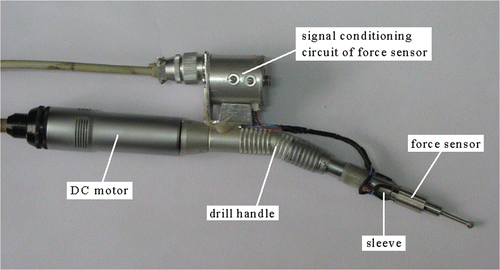
Two sensors, specifically a current sensor (CHB-25NP; Beijing SENSOR Electronics Co., Beijing, China) and a force sensor (Model RN20 strain gauge; Jinan Jinzhong Electronic Scale Corporation, Jinan, China), were installed on a modified otological drill (ZCW-1; 21st Institute, China's Ministry of Machinery and Electronics, Shanghai, China).
The current sensor was used to measure the electromagnetic torque of a DC motor. The relationship between current I and electromagnetic torque T is as follows:where C is a constant. According to the data sheet for the drill, the measurement range of the current sensor is from 0 to 2.5 A.
The force sensor was used to measure the normal cutting force at the milling surface. A sleeve was added in front of the drill handle Citation[8]. Through a sliding bearing installed in the front of the sleeve, the normal cutting force F of the drill bit can be transferred to the sleeve (). Four strain gauges were bonded onto the sleeve: These could measure the normal cutting force F by measuring the elastic deformation occurred on the sleeve. As the rotating drill bit may stir up blood or other corrosive liquids, the strain gauges and signal conditioning circuit are covered by protective cases. The force sensor could measure two orthogonal component forces Fx and Fy. The normal cutting force F is calculated as follows:
The measurement range of the force sensor is from −5 N to 5 N, with a resolution of 0.005 N and an accuracy of 0.05 N.
The sample rate of each sensor signal channel is 1024 SPS. To suppress sensor noise, an oversampling method was used Citation[10]. The input of the recognition method is the mean of the sample data:where
is the input data of the recognition method at time t, updated every 0.0156 seconds, and x16t+j denotes sample data.
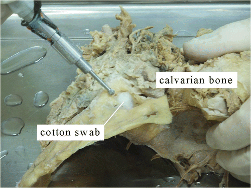
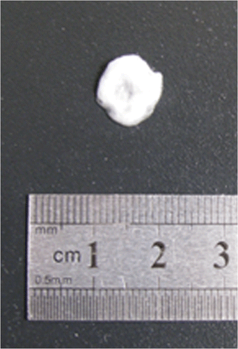
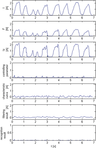
The material used in the experiment was calvarian bone that had been fixed in formalin (). Five surgeons were invited to participate in the experiment. They each made 100 tests of normal milling and 40 tests with cotton swab entanglement. The diameter of the drill bit used was 4 mm. The cotton swabs () were very small and thin, being less than 1 cm2 with an irregular shape (during surgery they are torn off individually by the surgeon and placed where needed). The swabs were wet and weighed less than 0.1 g. shows the tests of normal milling, including nine distinct milling processes. shows the tests with cotton swab entanglement, including four milling faults. Because the focus of this paper is the dynamic processing of sensor signals, the sensor zero point can be shifted to an idling value. That is, when the drill is running at idle, the outputs of the sensors are zero.
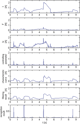
The experimental data showed that the indicators of cotton swab entanglement are significant and distinctive. However, the interferences are also very serious. When the drill bit entangles a cotton swab, the sensor signals undergo obvious changes. Because the swab entangles the rotating drill bit and increases the load on the DC motor, the current rises rapidly (>1 A and faster than 5 A/s). The normal cutting force also increases simultaneously, because the drill bit is being jacked up by the cotton swab. After the entanglement, as the cotton swab is pulled up from the bone surface by the drill bit, the force signal decreases, while the current shows little change because the cotton is still rotating with the drill bit and the load of the motor does not decrease ().
Even though the cotton swab could make the current and force increase rapidly, similar phenomena are also observed during normal milling. When a very strong force is applied to the drill by the surgeon, both the current and the force signal increase rapidly (>1 A and faster than 4 A/s for the current) (), and these processes would cause interference. Moreover, because each surgeon has his own method of manipulating the drill, signal diversity can also cause interference. These interferences are prone to being identified as milling faults.
To identify milling faults exactly, the DC motor model was induced to extract the essential differences between cotton swab entanglement and normal milling from the original sensor signals.
Feature analysis and extraction
During normal milling, though the current and force may increase as rapidly as with cotton swab entanglement, the dynamic relationship between the resistance moment and electromagnetic torque can show the differences between two milling states.
The otological drill is driven by a DC motor. During the milling process, there are two opposite torques acting on the drill bit: the resistance moment Tz caused by bone and the electromagnetic torque T caused by the DC motor. In accordance with the DC motor model Citation[11], the mathematical relation between Tz and T can be described by a differential equation:where Tm is the time constant of the motor and can be measured experimentally Citation[12]. In this case, Tm was approximately 0.09 s. The solution of Equation 4 is related not only to the resistance moment, but also to the initial value of the electromagnetic torque. That is, the solution of Equation 4 is related to the milling process before any milling faults occur.
This paper will first discuss the case where cotton swab entanglement occurs in the early stage of a milling process, then extend the conclusion to the case where a milling fault occurs during a milling process.
Between each milling process (milling fault or normal milling), the drill is running idle. The electromagnetic torque is a constant and is equal to the resistance moment. To simplify the analysis, the idling value can be subtracted from the electromagnetic torque. The resistance moment is processed in the same way. After processing, the initial values of Tz and T for the milling processes are equal to 0.
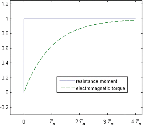
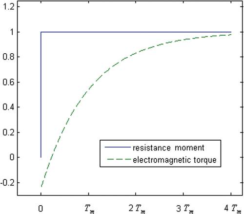
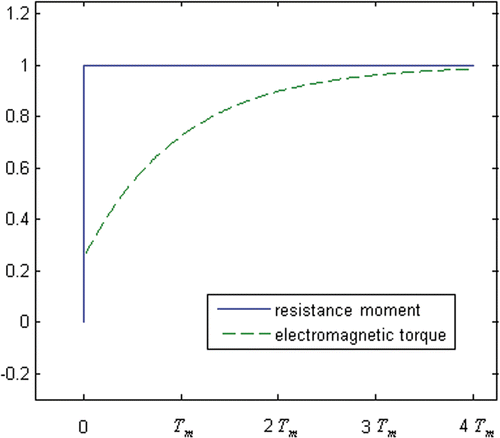
At the beginning of a cotton swab entanglement, because the load of the motor increases suddenly, the current increases significantly in a short time (<Tm) (). The resistance moment Tzc can be simplified to a step signal:
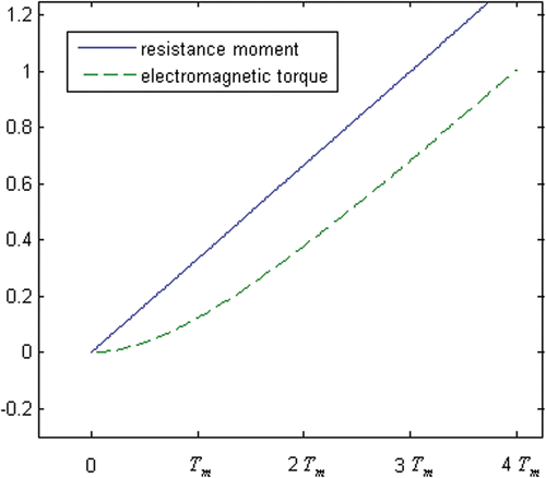
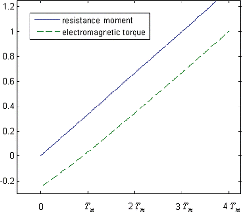
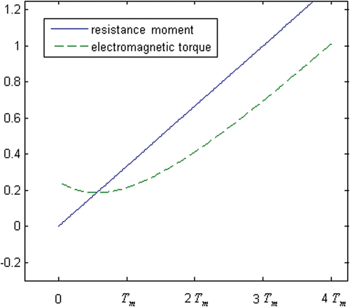
During normal milling, a milling process often lasts for some time (0.5 to 2 s) (). Because a rapid increase in current is one of the important indicators of cotton swab entanglement Citation[7], Citation[8], this paper need only analyze the process by which the resistance moment increases. When the drill bit is milling bone, Tzn will continue to increase for a short time. This can be simplified as follows:where k1 is the speed of the resistance moment. When a very strong force is applied to the drill by the surgeon, k1 is very large and is similar to that of a milling fault.
The electromagnetic torque can show the differences between two milling states. During cotton swab entanglement, the solution of Equation 4 is as follows:where Tc(t) is the electromagnetic torque of the cotton swab entanglement at time t. Tc increases very quickly at first, and then slows down ().
During normal milling, the solution of Equation 4 is as follows:where Tn(t) is the electromagnetic torque of normal milling at time t. The process for Tn is in contrast to that for Tc: It increases very slowly at first, and then accelerates ().
In conclusion, the early stage of a milling fault differs from that of normal milling. At the beginning of cotton swab entanglement, the electromagnetic torque increases rapidly, but during the early stage of normal milling, electromagnetic torque increases only slowly. It requires milling for some time to make the electromagnetic torque increase as rapidly as with a milling fault.
Clinical application of this technique requires identification of milling faults in real time. To meet this requirement, the early stage of a milling process is first identified and then fused with the electromagnetic torque. If the current milling stage is the beginning of a milling process and the electromagnetic torque increases rapidly, it can be deduced that the drill bit is just entangled with the cotton swab.
Thus, identifying the current milling stage is the core of the recognition method. In this paper, the dynamic relationship between the electromagnetic torque Tn(t) and the resistance moment Tzn(t − Δt) is used to identify the milling stage in real time. This method is more practical than the method of comparing the electromagnetic torque with a threshold. Therefore, the recognition method will be extended to the case where a milling fault occurs in a milling process. At this time, the early stage of a milling fault cannot be identified by comparing the electromagnetic torque with a threshold.
The dynamic relationship can be determined by discussing the conditions under which inequality (Equation 9) is right.
During normal milling, according to Equation 8, the solution of time interval Δt is as follows:
When a small time difference Δt (e.g., Δt < 0.5Tm) is chosen, Tn(t) > Tzn(t − Δt) only occurs at an early stage of a milling process (t < 0.69Tm); at other stages, Tn(t) < Tzn(t − Δt). Thus, the milling stage at time t can be identified by comparing Tn(t) with Tzn(t − Δt).
During cotton swab entanglement, the dynamic relationship is similar to that in normal milling. Only when the drill bit is just becoming entangled with a cotton swab is Tc(t) > Tzc(0). However, in contrast to normal milling, the electromagnetic torque Tc is increasing rapidly during this time. In other circumstances, Tc(t) < Tzc(t − Δt).
Therefore, milling stages can be identified by the dynamic relationship in real time. Cotton swab entanglement can be identified by fusing the information on the current milling stage and the electromagnetic torque. Firstly, given a small time difference (e.g., Δt < 0.5Tm), if the electromagnetic torque at time t is greater than the resistance moment at time t − Δt, it can be deduced that the current milling stage is at the beginning of the milling process. If the electromagnetic torque is increasing rapidly during this time, it can be deduced that cotton swab entanglement is occurring; otherwise, the milling state is normal milling.
As the current and cutting force signals are more easily measured than torques, in order to make the above conclusion practical, the dynamic relationship between the sensor signals is deduced through the dynamic relationship between the electromagnetic torque and the resistance moment.
According to Equation 1, the electromagnetic torque can be calculated from the current, as the torque is proportional to the current. The resistance moment must be calculated by the cutting force model.
There are three kinds of cutting forces at the drill bit: tangential, normal and axial Citation[8], Citation[13]. The normal cutting force can be measured by a force sensor, whereas the tangential cutting force and bone resistance force are action and reaction. The resistance moment can be calculated by multiplying the tangential cutting force by the drill bit radius R.
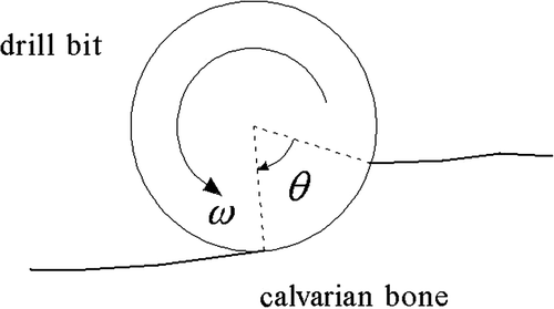
The normal cutting force can be calculated as follows:Where F(t) is the normal cutting force at time t, N is the number of teeth on the drill bit, θt is the contact angle between the drill bit and the bone at time t (), and fr is a constant. During normal milling, as
, the equation of F(t) can be reduced as follows Citation[8]:
F is approximately proportional to θ. According to our previous research Citation[8], the equation to calculate the resistance moment is as follows:
where Tz(t) is the resistance moment at time t, and ft is a constant. It can be deduced that the normal cutting force and resistance moment change with θ simultaneously and the normal cutting force is proportional to the resistance moment Citation[8]. Therefore, the resistance moment can be obtained by amplifying the force signal as follows:
When milling steadily, the electromagnetic torque T(t) is equal to the resistance moment Tz(t). The current and force signal have the following relationship:
Let Iz(t) be the estimated current; it can be calculated from the resistance moment Tz(t) or force signal F(t) as follows:
When milling steadily, Iz(t) = I(t). If the drill bit is entangling a cotton swab or the surgeon's force is changing suddenly, then, according to the relationship between T(t) and Tz(t), the process for Iz(t) is different from that for I(t).
The dynamic relationship between the electromagnetic torque and resistance moment can be replaced by the dynamic relationship between the current I and the estimated current Iz. The data processing is the same. In a small time interval Δt, if I(t) > Iz(t − Δt) and the current is increasing rapidly, it can be deduced that cotton swab entanglement is occurring.
The estimated current Iz is calculated by enlarging the force signal. To suppress sensor noise, is calculated from the mean values of the current and force data in the steady milling process:
However, there are some defects in the dynamic relationship. During surgery, as cotton swab entanglement often occurs in the course of a normal milling process, the initial value of the electromagnetic torque may not be 0, which may disturb the dynamic relationship. Thus, the features that indicate when cotton swab entanglement occurs during a milling process need to be analyzed.
To simplify the analysis, the resistance moment and the electromagnetic torque are shifted to the origin. The resistance moment is still represented by Equations 5 and 6, and its initial value is adjusted to 0. When a milling fault occurs in a normal milling process, the electromagnetic torque may or may not be larger than the resistance moment. Also, as the resistance moment is shifted to the origin, the electromagnetic torque may or may not be larger than 0 after being shifted. However, because the resistance moment and electromagnetic torque are shifted synchronously, their relationship is unchanged.
The initial value of the electromagnetic torque is set at T0. If the initial value of the electromagnetic torque is larger than that of the resistance moment, T0 > 0; if the initial value of the electromagnetic torque is smaller than that of the resistance moment, T0 < 0.
When cotton swab entanglement occurs during a normal milling process, the solution of Equation 4 is as follows:
The dynamic relationship between the resistance moment Tzc and the electromagnetic torque Tc is shown in (T0 < 0) and 10 (T0 > 0). When T0 < 0, the increase in Tc is larger than that for T0 = 0; when T0 > 0, the increase in Tc is smaller than that for T0 = 0.
During a normal milling process, if a very strong force is suddenly applied to the drill by the surgeon, the electromagnetic torque will also increase rapidly. The solution of Equation 4 is as follows:
The dynamic relationship between resistance moment Tzn and the electromagnetic torque Tn is shown in (T0 < 0) and 12 (T0 > 0). When T0 < 0, the increase in Tn is larger than that for T0 = 0. When T0 > 0, the increase in Tn is smaller than that for T0 = 0, and Tn sometimes even decreases.
Compared with Equations 7 and 8, Equations 18 and 19 add . The change in T0 would disturb the dynamic relationship.
When T0 > 0, the interference is not serious. During normal milling, the electromagnetic torque Tn may be larger than the resistance moment Tzn. However, because Tn is decreasing (), it is easy to distinguish milling faults from normal milling. If Tn < Tzn, the waveform of Tn is similar to that for T0 = 0 ( and ). Also, during a milling fault, the electromagnetic torque waveform is similar to that for T0 = 0 ( and ). The dynamic relationship can hold true for the case where T0 > 0. However, when T0 < 0, there are some defects in the dynamic relationship. On the one hand, during a milling fault, Tc(t) is much smaller than Tzc(t) (), and Δt must be enlarged so as not to omit any milling faults. On the other hand, during normal milling, Tn(t) increases rapidly from the beginning, its speed being similar to that of the milling fault (). Through the combined action of the enlarged Δt and the rapid electromagnetic torque Tn(t), it is easy to identify normal milling as a milling fault.
To eliminate the interference caused by T0, the recognition method presents a characteristic curve. This curve and the dynamic relationship are two complementary features. They can be fused together to suppress interferences by means of an adaptive filter.
Recognition method design
The recognition method first calculates the characteristic curve and dynamic relationship, then fuses them together using an adaptive filter, and finally uses the fusion result to identify milling faults through a rule base.
The characteristic curve is calculated by subtracting the estimated current Iz from the current I. Before the subtraction, a running mean filter is used to preprocess Iz. This filter can filter out the pulse in Iz caused by the cotton swab. During normal milling, as the current changes with the surgeon's force, Iz and I are similar (). Thus, the characteristic curve is much smoother than the current (ranging from −0.4 to 0.4 A and slower than 1 A/s) (). However, during cotton swab entanglement, the characteristic curve can increase rapidly, because the pulse in Iz has been smoothed. Therefore, the characteristic curve can reserve the process by which the current increases (>0.5 A and faster than 5 A/s) ().
The characteristic curve and the dynamic model are two complementary features. When the characteristic curve is disturbed, the output of the dynamic relationship is still reliable; and when the output of the dynamic relationship is disturbed, the characteristic curve can remain stable.
As the characteristic curve is obtained by calculation, sensor noise may cause interference with the curve, and the curve might be unsteady and subject to fluctuations. However, sensor noise can hardly disturb the dynamic relationship. When the current increases slowly, because the sensor noise is small, it is unable to make the current increase as significantly as a milling fault does, and the dynamic relationship cannot be disturbed. When the current increases rapidly, the speed of the resistance moment k1 is very high. According to Equation 8, the difference between I and Iz is large. The sensor noise is small and unable to make I(t) larger than Iz(t − Δt) in a small Δt, so the dynamic relationship cannot output a wrong result.
The dynamic relationship is easily disturbed when T0 < 0; however, the characteristic curve can remain stable at this time. When T0 < 0, the changing process of the electromagnetic torque is similar to that of the resistance moment (), and the difference between them can be taken as a constant. Thus, the characteristic curve is stable.
As the characteristic curve and dynamic relationship are two complementary features, their respective interferences can be suppressed efficiently by fusing them together, and an adaptive filter was designed to fuse them. The filter consisted of an adaptive IIR filter and a controller (). The characteristic curve is the input signal, and the control signal is the dynamic relationship. The adaptive IIR filter is a first-order IIR filter Citation[14], Citation[15]:where y(t) is the filtering result at time t, x(t) is the characteristic curve at time t, and η(t) denotes the controlling parameter at time t. Adjusting η(t) could control the filtering effect of the adaptive IIR filter; the smaller the η(t), the stronger the filtering effect.
When the recognition method is running on the computer, the estimated current Iz is calculated first, and then the dynamic relationship between I(t) and Iz(t − Δt) is extracted to control the adaptive filter.
The controlling parameter η(t) is adjusted according to the dynamic relationship between I(t) and Iz(t − Δt). The test results indicated that the recognition result is perfect when Δt = 0.5Tm. If I(t) < Iz(t − Δt), the filtering effect of the adaptive filter is set to very strong. Otherwise, η(t) is adjusted according to the current increment. The smaller the current increment, the stronger the filtering effect.
At the beginning of a cotton swab entanglement, I(t) > Iz(t − Δt), the current increases rapidly, and η(t) is large. The filtering effect is very weak, and the increasing process in the characteristic curve can be reserved ().
During normal milling, the adaptive filter can make the filtering result very smooth. When the current is decreasing, the filtering effect is set to the strongest level, because milling faults only occur when the current is increasing. When the surgeon's force is stable, I(t) > Iz(t − Δt) only occurs at the beginning of a milling process. At this point, as the current increases slowly, η(t) is small and the filtering result is smooth. When a very strong force is applied to the drill in a milling process, as the initial value of the electromagnetic torque T0 ≠ 0, I(t) might be larger than Iz(t − Δt) and the dynamic relationship may be disturbed. If the current increases very rapidly during this process, η(t) is large, and the adaptive filter is very weak. However, because I(t) is similar to Iz(t) (), the characteristic curve is stable during this time. The filtering result can remain smooth and is rarely disturbed by the change in the surgeon's force ().
Compared to the current and the characteristic curve, the filtering result is more suitable for identifying milling states. During normal milling, the filtering result is much smoother than the characteristic curve (having a range of −0.2 to 0.2 A and being slower than 0.5 A/s) (). During cotton swab entanglement, the filtering result is similar to the characteristic curve and increases rapidly (>0.5 A and faster than 5 A/s) ().
As the distinction between two milling states is significant in the filtering result, milling faults can be identified precisely using a simple rule base. The rule base is designed according to the waveform of the filtering result Citation[16], Citation[17]. First, the increment of the filtering result is calculated with a threshold of 0. If the calculation result is larger than 0, then the output of Equation 21 can serve as the recognition result Z(t):where y(t) is the filtering result at time t, and C2 denotes a constant.
If the recognition result is larger than 0.5, it can be concluded that the milling fault is occurring ( and ).
Results and discussion
The recognition method was tested. Five surgeons used the modified otologic drill to perform the experimental procedure on calvarian bone which had been fixed in formalin (). Each surgeon made 100 tests of normal milling and 40 tests with cotton swab entanglement ().
At the beginning of the cotton swab entanglement, the changes in the sensor signal are very clear, as shown in . Both the current and force signals, especially the current, increase rapidly (current > 1 A and faster than 5 A/s). However, a similar phenomenon might also occur in the processes of normal milling, as shown in . If a very strong force is applied to the drill, the current will increase rapidly (>1 A and faster than 4 A/s).
To identify milling states exactly, some important features, including the characteristic curve and the dynamic relationship between the sensor signals, are extracted using the DC motor model and the cutting force model. These have complementary advantages and can be fused together using an adaptive filter. Compared with the sensor signals or characteristic curve, the filtering result could make the features indicating cotton swab entanglement more significant. During normal milling, interferences are suppressed efficiently, and the filtering result is very smooth. According to the filtering results, milling states can be recognized precisely using the rule base. It can be seen from and that cotton swab entanglement and normal milling are clearly distinguished in the recognition result.
In the experiment, the average recognition rate for milling faults was 90%. Despite the surgeons each having their own methods of manipulating the drill, the interferences could be suppressed efficiently, and there were fewer erroneous identifications during normal milling (). Only 2% of all normal millings were identified as milling faults.
It was also shown that the recognition method is able to identify milling faults and give a timely warning. The core of this method is comparing the current I(t) and the estimated current Iz(t − Δt). If the drill bit starts to entangle a cotton swab at time t − Δt, the milling fault can be identified at time t. In our experiment, Δt = 0.5Tm. This indicated that the recognition method would raise the alarm within 0.5Tm (<0.05 s) of the start of the entanglement.
Conclusions
This paper has presented a recognition method for monitoring the milling state of an otological drill. The method could identify the drill bit's entanglement with a cotton swab exactly and was rarely disturbed by such interferences with the milling process. It could adapt to different surgeons and help them to improve the safety of the operation.
Acknowledgments
The authors would like to thank Beijing Yabolun Technological Co. Ltd. for modifying the otologic drill for this work. Special thanks also go to Li Guozheng for his advice and enthusiasm.
Declaration of interest: This work has been supported by the Beijing Municipal Natural Science Foundation (Grant No. 4092027) and the Fundamental Research Funds for the Central Universities (No. FRF-TP-09-017B).
References
- Green JD, Shelyon C, Brachmann DE. Iatrogenic facial nerve injury during otologic surgery. Laryngoscope 1994; 104(8)922–926
- Strauss G, Koulechov K, Hofer M, Dittrich E, Grunert R, Moeckel H, Müller E, Korb W, Trantakis C, Schulz T, et al. The navigation-controlled drill in temporal bone surgery: A feasibility study. Laryngoscope 2007; 117(3)434–441
- Tolsdorff B, Petersik A, Pflesser B, Pommert A, Tiede U, Leuwer R, Höhne KH. Individual models for virtual bone drilling in mastoid surgery. Comput Aided Surg 2009; 14(1–3)21–27
- Allotta B, Giacalone G, Rinaldi L. A hand-held drilling tool for orthopedic surgery. IEEE/ASME Trans Mechatron 1997; 2(4)218–229
- Coulson CJ, Reid AP, Proops DW, Brett PN. ENT challenges at the small scale. Int J Med Robotics Comput Assist Surg 2007; 3(2)91–96
- Shoham M, Lieberman IH, Benzel EC, Togawa D, Zehavi E, Zilberstein B, Roffman M, Bruskin A, Fridlander A, Joskowicz L, et al. Robotic assisted spinal surgery – from concept to clinical practice. Comput Aided Surg 2007; 12(2)105–115
- Shen P, Feng G, Cao T, Gao Z, Li X. Automatic identification of otologic drilling faults: A preliminary report. Int J Med Robotics Comput Assist Surg 2009; 5: 284–290
- Cao T, Li X, Gao Z, Feng G, Shen P. Automatic identification of otological drilling faults: An intelligent recognition algorithm. Int J Med Robotics Comput Assist Surg 2010; 6: 231–238
- Wang T, Luan S, Hu L, Liu Z, Li W, Jiang L. Force-based control of a compact spinal milling robot. Int J Med Robotics Comput Assist Surg 2010; 6: 178–185
- Sandler EA, Gusev DA, Milman GY, Podolsky ML. Estimating from outputs of oversampled delta-sigma modulation. Signal Processing 1997; 59(3)305–311
- Jakubowicz A, Nougaret M, Perret R. Simplified model and closed-loop control of a commutatorless DC motor. Industry Applications 1980; 16(2)165–172
- Wu W, DC motor identification using speed step responses. Proceedings of the American Control Conference, Baltimore, MD, 30 June–2 July 2010. pp 1937–1941
- Zaman MT, Kumar AS, Rahman M, Sreeram S. A three-dimensional analytical cutting force model for micro end milling operation. Intl J Mach Tool Manu 2006; 46: 353–366
- Radenkovic M, Bose T. Adaptive IIR filtering of nonstationary signals. Signal Processing 2001; 81(1)183–195
- Park MS, Song WJ. Adaptive IIR filtering with combined regressor and combined error. Signal Processing 1997; 56(2)191–197
- Song F, Smith SM, A simple weight based fuzzy logic controller rule base reduction method. Proceedings of the 2000 IEEE International Conference on Systems, Man, and Cybernetics, Nashville, TN, October 2000. pp 3794–3799
- Lee YH, Cheng AMK. Optimizing real-time equational rule-based systems. IEEE Trans Software Eng 2004; 30(2)112–125
