Abstract
Objective: In contrast to preoperative image-based 3D navigation systems, which require surgeon-dependent registration, an intraoperative cone-beam computed tomography (cb-CT) image-based 3D navigation system allows automatic registration during the acquisition of 3D images intraoperatively. Thus, the need for spinal exposure for point matching is obviated, making a cb-CT image-based navigation system ideal for use in minimally invasive spinal procedures. Conventionally, the dynamic reference frame (DRF) is mounted to an adjacent spinous process or iliac bone through a separate incision. However, the close proximity of the DRF to the surgical area may result in its interfering with the surgical procedure or causing streak artifacts on the navigation images. Cutaneous placement of the DRF overlying the sacral hiatus is one possible solution to these problems, but such a placement does not provide a solid bony fixation point and is distant from the surgical area, both of which factors may hinder the accuracy of the navigation. The purpose of this study was to evaluate the accuracy of a novel idea for DRF placement in a series of mini-open transforaminal lumbar interbody fusion (TLIF) procedures performed with intraoperative cb-CT image-based 3D navigation.
Methods: From June 2009 to December 2009, 20 patients underwent mini-open TLIF for a total 82 pedicle screws placed in the lumbar spine with cutaneous placement of the DRF overlying the sacral hiatus. The pedicle screws were inserted under navigational guidance using cb-CT data acquired intraoperatively with a Medtronic O-arm. Screw positions were subsequently checked with a final intraoperative cb-CT scan. Nineteen patients underwent single-level fusion (8 at L4–5, 6 at L5–S1, 4 at L3–4, and 1 at L2–3) and one patient underwent two-level fusion (from L3–5).
Results: There were 4 (4.9%) pedicle perforations greater than 2 mm out of the 82 pedicle screw insertions in the 20 patients. Two of these breached screws were repositioned and confirmed to be in place with a final intraoperative cb-CT. There were no complications of neural injury associated with these perforations.
Conclusion: A cutaneously mounted DRF overlying the sacral hiatus provides accuracy in intraoperative 3D image guided navigation for mini-open TLIF that is comparable to that obtained in other reported series using a fixed bony attachment point for the DRF.
Introduction
The concept of minimally invasive spinal surgery requires the use of some form of surgical navigation guidance. Traditionally, fluoroscopy was necessary in certain procedures, such as pedicle screw insertion during minimally invasive transforaminal lumbar interbody fusion (TLIF). However, fluoroscopy has a lower accuracy, and there is a risk of radiation exposure for the surgical team, leading to its being supplanted by computer-assisted navigation. Computed tomography (CT) scan-based navigated screw placement has evolved into an acceptable modality by which surgical accuracy can be improved Citation[1]. However, during minimally invasive spinal surgery, preoperative CT image-based navigation cannot be applied, as the common posterior spinal anatomical landmark is generally not visible, making surgeon-dependent registration impossible. Furthermore, there is also a change in the inter-segmental anatomy between the preoperative supine position and the final intraoperative prone position. These problems have been addressed by the introduction of intraoperative imaging-based navigation. One of these modalities is the intraoperative cone-beam CT (cb-CT), as represented by the Arcadis Orbic Isocentric C-arm from Siemens Medical Solutions and the O-arm from Meditronic.
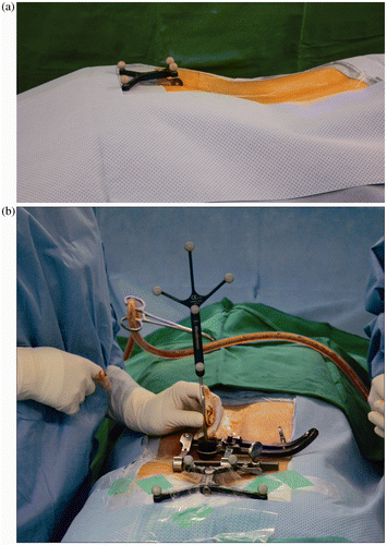
The advent of intraoperative cb-CT has eliminated the need for registration of vertebral levels for spinal image guidance, as was required in previous point-matching techniques. However, optimal navigation accuracy also depends on the position of the dynamic reference frame (DRF). Ideally, the DRF should be fixed to the spinal level being instrumented, but whereas this is straightforward in large open spinal procedures, reliable placement of the DRF is difficult during minimally invasive spinal surgery. Placement of the DRF on an adjacent spinous process would require a separate incision, and the close proximity of the DRF may interfere with the surgical procedure itself Citation[2], Citation[3]. Even though the DRF is made from titanium, which produces fewer streak image artifacts Citation[4], the close proximity of its placement to the surgical site, either on the spinous process or on the posterior superior iliac spine (PSIS), has been noted (by our own observation as well as in the literature) to produce significant metal artifacts on cb-CT images Citation[4]. Various solutions have been proposed to alleviate this problem. The PSIS has been used as a substitute placement site for the DRF Citation[2]; however, it remains a source of streak artifact, especially when surgery is required at the L5–S1 level. Furthermore, the close proximity of the DRF to this level may also hinder the intended surgical procedure. Another suggested solution was the construction of an aluminum base, which would produce fewer streak artifacts, on which the DRF could be mounted Citation[5]. However, the DRF is the focal point of synchronization between a virtual data set and the real anatomical situation, and any small changes in angle, position, or height of the DRF may result in desynchronization of the system. In other words, an erected, antlered DRF near the working area lends itself to being a source of error. The magnitude of these additional sources of error may be minimized by reducing the distance between the DRF and the end of the base Citation[5]. Having previously experienced the above-mentioned desynchronization and image artifact problems, and in an attempt to alleviate these issues, we attached the DRF cutaneously overlying the sacral hiatus () using OpSite incise drapes (Smith & Nephew, Hull, UK). This study focuses on our experience with this novel approach of attaching a DRF cutaneously overlying the sacral hiatus, and assesses the accuracy of pedicle screw insertion in the lumbosacral spine during mini-open TLIF.
Figure 1. (a) DRF attached to the sacral hiatus with sterile tape. (b) The DRF is positioned out of the way of the surgeon.
Patients and methods
Patients
A total of 20 patients who underwent mini-open TLIF with pedicle screw fixation using cb-CT image guidance from June 2009 to December 2009 were included in the study. The 20 patients (11 females and 9 males) had a mean age of 55.9 years (range: 34–74 years) and a preoperative mean BMI of 24.4 (range: 19.9–28.6) (). Five patients had spondylolytic spondylolisthesis, and the remaining 15 had degenerative spondylolisthesis. Nineteen patients underwent single-level fusion from L2–3 to L5–S1 (1 at L2–3, 4 at L3–4, 8 at L4–5, and 6 at L5–S1), and 1 patient underwent a two-level fusion (L3–5) using the mini-open TLIF technique Citation[6]. All patients provided informed consent prior to undergoing surgery. A total of 82 screws were inserted under navigation guidance using intraoperatively acquired cb-CT (O-arm) data without any additional usage of C-arm fluoroscopy. In each case, the duration of operation and any intraoperative complications were recorded.
Table I. Summary of demographic data.
Surgical procedures
All the surgical procedures performed were mini-open TLIFs, based on the technique described by Mummaneni and Rodts Citation[6], with intraoperative computer-assisted spinal navigation using the cb-CT (O-arm, Medtronic) and the StealthStation® Navigation System (Medtronic Navigation, Louisville, CO). After endotracheal general anesthesia, the patient was placed in a prone position using a Wilson frame (MDT Corp., Torrance, CA) on a carbon-fiber operating table. The buttock and sacral hiatus areas were covered with sterile transparent adhesive film to eliminate any air or fluid gaps between the skin and film. Next, the planned surgical area was cleaned and draped. The DRF was then mounted cutaneously overlying the draped sacral hiatus area with sterile OpSite incise drapes (). The patient was subsequently covered temporarily with a large transparent drape, and the cb-CT O-arm device was positioned so that the intended surgical site was in the center of the fluoroscopic field in the anteroposterior (AP) and lateral planes. The large transparent drape serves as a barrier to the sterile field and is typically not in contact with the cb-CT device. Intraoperative scanning was then performed, resulting in a cb-CT data set that was automatically registered to the image guidance system. The total time for positioning of the cb-CT device and for image acquisition was typically less than 5 min. The cb-CT device was then taken out of the field and the transparent drape removed. After acquiring the intraoperative cb-CT data set, computer-aided navigation based on the intraoperative scanned images commenced. Using the navigation probe tip, the ideal screw entry points were sought in order to determine the precise skin incision based on the virtual elongated navigation trajectory. Surgical exposure was subsequently performed using a paraspinal Wiltse approach Citation[7]. After exposing the relevant bony structures with retractors, the navigation accuracy was reconfirmed by touching the visible anatomic landmarks using the navigation probe and comparing them with the scanned images.
Pedicle entry points were based on navigation guidance, and pilot holes were made with a 3-mm high-speed burr to avoid any motion error that could possibly arise from vigorous awl penetration. The direction of the pilot pedicle hole was rechecked with the navigation probe, and 5.5-mm tapping was done to a depth of 40 mm from the entry point. After confirming that no bony perforations had been made, a final check of the completed tapped bony tunnel was performed with the navigation probe, and the images were recorded in the navigation system (virtual screw data set). Screws were then inserted, with adjacent level and contralateral screw insertions being performed in a similar manner. After all the screws had been inserted, a second cb-CT scan was performed to verify their actual positions (actual screw data set). In those cases where screw malpositioning occurred, repositioning of the screw was done under navigation guidance again, and a final cb-CT scan was performed. The remainder of the transforaminal interbody fusion was performed with the operating microscope as described elsewhere by various authors Citation[6], Citation[8]. Upon completion of the whole procedure, with the final placement and tightening of the connecting rods on the pedicle screws, an intraoperative radiograph was taken in both the AP and lateral planes.
Assessment of screw placement
Assessment of the navigated pedicle screw insertion was divided into two components: accuracy of navigation and validity of navigation
Accuracy of navigation. The accuracy of the navigation is an assessment based on the degree of perforation by the inserted pedicle screws. The actual positions of the inserted screws were confirmed with the second cb-CT scan in all cases (82 screws). Pedicle perforation was graded from 0 to III in 2-mm increments as follows: grade 0: no pedicle breaches; grade I: only the threads were outside the pedicle (less than 2 mm); grade II: the core screw diameter was outside the pedicle (2–4 mm); and grade III: the screw was entirely outside the pedicle Citation[9]. The assessment of the images and measurements of the pedicle perforations were performed by a surgeon who was independent of the study, using a computerized imaging software system (StarPACS, ΠViewStar™).
Validity of navigation. The validity of the navigation was then assessed by comparing the differences between the actual positions of the inserted pedicle screws based on the second cb-CT scan and the recorded images of the navigation probe in the 5.5 × 40 mm tapped holes (the virtual intended screw location). There were, however, only 56 images of virtual intended screws as the recorded navigation images were lost in six cases (representing 26 screws). Nevertheless, the cb-CT–scanned images of all 82 screws were present, and ultimately determined whether there had been any actual perforation by the inserted screws.
Two parameters were measured: the screw axis angle in the axial plane (SAA) and the screw axis angle in the sagittal plane (SAS) (). These angles are defined as follows: The SAA is the angle between the screw axis and the midline of the vertebra that bisects the body, spinal canal, and spinous process; while the SAS is the angle between the screw axis and the upper endplate of the screw-inserted vertebra.
Figure 2. (a) Recorded navigation image and measured SAA and SAS of virtual screw location. (b) Second cb-CT scan image after screw insertion, and measured SAA of actual screw location
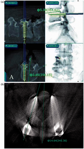
Both these angles were measured from the virtual intended screw location (the recorded navigation images of the navigation probe in the tapped pedicle hole) and the actual inserted screw location (the second cb-CT scan images). The virtual screw location, based on the navigation probe position in the tapped pedicle hole, is the intended final location of the screw, and its SAA and SAS values are deducted from the corresponding values measured from the cb-CT images showing the actual inserted screw location. The differences between these two values determined the validity of the navigation.
By convention, the SAA value is defined as positive if the measured angle converges towards the midline and negative for the opposite direction. The SAS value is defined as positive if the direction of the screw is away from the endplate and negative for the opposite direction. These measurements were performed by an independent surgeon using the computerized imaging software system (StarPACS, ΠViewStar™).
Statistical analysis
To assess inter-observer reliability, the measurement of the virtual/actual SAA and SAS was done by two different observers and the data sets were compared and assessed by means of reliability analysis with intraclass correlation coefficients (ICC). We also conducted ICC analysis with the data to assess the validity between the virtual and actual values; in other words, how accurately the actual screw was placed in the intended position. The single-measure two-way mixed model was used in the analysis with SPSS 14.0 K software.
Results
Operation time
The mean anesthesia time (from induction to reversal) was 210 ± 52.4 min (range: 120–345 min). Additional decompressive procedures were done in four cases, and total anesthesia time for the remaining 16 cases was 192.2 ± 37.2 min (range: 120–270 min).
Skin incision was performed at 18.5 ± 6.5 min (range: 10–30 min) after the induction of anesthesia. Within this period of time, patient repositioning into a prone position, skin preparation, sterile draping, cutaneous attachment of the DRF, O-arm scanning, navigation set-up, and acquisition of navigation data were all performed.
After inserting all the pedicle screws, the mean time for the second O-arm scan was 43.6 ± 11.9 min after commencement of anesthesia. The additional time between the second and third O-arm scans (for repositioning of screws) in the two cases with malpositioned pedicle screws was 72 and 93 min, respectively.
Accuracy of navigation
The second cb-CT O-arm scan after pedicle screw insertion revealed eight pedicle breaches (4 grade I, 2 grade II, and 2 grade III) in eight patients. The two grade III screws were reinserted and confirmed to be in the proper position with a third O-arm scan. The two grade II screws perforated the lateral wall of the pedicle but remained within the body of the vertebra, and were therefore not revised. The four grade I perforations comprised two medial and two lateral perforations. There was no correlation between BMI, screw breaches, and the level of fusion ().
Table II. Incidence of screw breach according to fusion level.
Validity of navigation
The SAA and SAS parameters could only be measured in 56 screws as data corruptions resulted in the loss of navigation images for 26 screws. The SAA difference between the actual and virtual screw positions was 5.33 ± 3.26° (5.27 ± 3.74° for observer 2), whereas the SAS difference was 3.01 ± 2.39° (3.70 ± 2.34° for observer 2). There was no significant difference in the SAA and SAS parameters between actual and virtual screw positions (). The SAA parameters showed good inter-observer reliability, and the SAS parameters showed moderate inter-observer reliability Citation[10].
Table III. Intraclass correlation coefficient (ICC) values in the analysis of the virtual/actual SAA and SAS validity.
Perioperative complications
Despite the eight pedicle perforations, there were no complications in the form of nerve injury, infection, or instability of the final instrumented construct.
Discussion
In any minimally invasive spinal procedure such as mini-open TLIF, there may be a paucity of identifiable landmarks to guide the surgeon in inserting pedicle screws. In a historical cohort of patients operated by anatomical landmarks, Amiot et al. reported an error rate of 15% in pedicle screw placement Citation[11]. In another recent meta-analysis by Kosmopoulos and Schizas, the rate of pedicle screw perforation in the absence of navigation was approximately 10% Citation[12]. The use of spinal navigation has considerably reduced the rate of screw misplacement to approximately 5% Citation[11], Citation[12]. As such, the aid of spinal navigation is essential in the accurate and safe placement of screws in minimally invasive spinal surgery. Traditionally, fluoroscopy has been used for spinal navigation in such procedures, and C-arm fluoroscopy has enabled improved accuracy of pedicle screw placement during mini-open TLIF. However, C-arm fluoroscopy has various inherent disadvantages: only mono-planar imaging at any given time, a crowded surgical field, the need to wear heavy lead shielding, the nonphysiological posture of the operating personnel due to the presence of the C-arm, and the risk of radiation exposure for the surgical team Citation[13], Citation[14].
Preoperative CT image-based navigation attempted to circumvent these problems. However, the need for surgeon-dependent multipoint registration, as well as the difference in the inter-segmental anatomy of the spine between the preoperative supine and final intraoperative prone positions, has made this modality less than ideal for minimally invasive spinal surgery. The introduction of intraoperative imaging-based navigation systems has not only eliminated these problems, but has also revolutionized minimally invasive spinal surgery. The combination of an intraoperative CT scanner with a navigation system has facilitated improved accuracy in screw insertion and allows enhanced control over the extent of decompression and tumor resection, as well as enabling detection of complications and generation and updating of the neuronavigation data set Citation[1]. Nevertheless, intraoperative imaging-based navigation does share some similarities with intraoperative imaging-based navigation, one of which is the surgeon's unfamiliarity with the device and the possibility of navigation desynchronization during surgery due to disruption of the DRF by vigorous surgical maneuvers.
The accuracy of the navigation system depends on the integrity of the connected components of the system. The DRF remains the key component that maintains the synchronization between the virtual data set and the actual anatomical positions, and stable reference frame fixation is therefore a critical step in navigated surgery. Any variation in the position of the DRF may result in desynchronization of the system, thus leading to inaccuracy of the navigation. The DRF should ideally be fixed to the spinal level being instrumented to increase the accuracy of the navigation. However, such a placement point is not possible in minimally invasive procedures such as mini-open TLIF. Placement of the DRF on an adjacent spinous process would entail a separate incision, and even in this position the DRF may hinder the surgical procedure Citation[2], Citation[3]. Furthermore, placement of the DRF on an adjacent spinous process may result in the generation of image artifacts during cb-CT scanning, which might also interfere with the navigation Citation[4]. Various solutions have been proposed to alleviate this problem.
Wired navigation tools have shown better constant signals. However, the presence of any additional wires could further aggravate an already crowded surgical field and could lead to interference with the procedure and with synchronization of the DRF itself. Furthermore, wired and dedicated tools tend to be specific for certain screw products only, and, in addition to being less versatile, they also require a larger financial investment.
A number of surgeons have successfully placed the reference frame away from the surgical field without compromising the accuracy of the navigation. Hott et al. Citation[15], Summers et al. Citation[16], and Nottmeier et at. Citation[17] successfully performed 3D image guided odontoid and cervico-occipital spine instrumentation by placing the reference frame on the headholders of their patients. With the reference frame fixed to the headholder, cervical screw fixations can be inserted without any mechanical obstruction of the surgeon's hands or instruments. Furthermore, the optical camera for the image guidance system was placed at the head of the bed, and thus there was no line-of-sight obstruction between the camera and the image guided instruments.
In lumbar spine surgery, Best et al. have used the PSIS as an alternative site for placing the DRF Citation[2]. However, based on our experience, DRF placement at this site is also a source of streak artifacts, especially for L5–S1 level surgery, and the close proximity of the DRF to this level may also hinder any surgical procedures. Furthermore, despite the lack of any complications in the series considered by Best et al., fiducial iliac screws invariably have the disadvantage of invasivity-related risk of infection or postoperative pain Citation[18]. Another suggested solution was the use of a tall aluminum base, which produces fewer streak artifacts, on which the DRF is attached Citation[5]. However, an erected, antlered DRF can also lead to less accuracy. The magnitude of these additional sources of error may be minimized by reducing the distance between the DRF and the end of the base Citation[5]. Rosenberger et al. also reported the use of radio-dense markers glued to the patient's skin as registration points, with the DRF being mounted to the side rail in the stabilization of pelvic bone fracture under preoperative image-based navigation Citation[18].
We have previously tried mounting the DRF on a pole bent at 90° and firmly fixed to the side rail of the operation table. However, this construct could not maintain sufficiently accurate synchronization. Hence, based on the above-mentioned ideas, we decided to mount the DRF in a low-profile manner, cutaneously overlying the sacral hiatus area, away from the surgical field, without the use of any special device, and non-invasively, obviating the need for an additional skin incision.
As the DRF was placed away from the surgical site, it did not interfere with the surgical procedure, and its position was not disturbed in any way. The skin incision and the path of the subsequent paraspinal approach were guided precisely by a virtual elongation trajectory of the navigation probe. This minimized the risk of a misplaced incision that might have caused difficulty with instrumentation and, hence, movement of the patient with respect to the DRF.
Despite the absence of any bony fixation, there was minimal movement of the DRF. We also ensured minimal movement of the patient while performing the surgery. A high-speed burr was used to the make the pilot pedicle entry point, so there were minimal push or pull movements on the spinal column. All of the preparatory steps of pedicle screw placement – pilot entry point, pedicle track creation with a high-speed burr, and pedicle probing and tapping – were followed by navigation probe assessment. It should be emphasized that, with any navigation technique, the surgeon must confirm the navigation accuracy before drilling each hole. This confirmation is accomplished by comparing the anatomic landmark on the spinal level at which the hole is to be drilled. If navigation is not accurate, then a re-scan must be performed. However, in our series, there was no need for a repeat initial scan or for the use of any additional C-arm fluoroscopy.
Limit of allowable pedicle perforations
Considering the large variety of reported methods for ensuring screw placement accuracy, we decided to use the classification described by Rajasekaran et al. Citation[9] and adopted the consensus of other studies in the literature that perforations of less than 2 mm were safe and acceptable Citation[1], Citation[9], Citation[19–23]. Perforations of less than 2 mm on CT scans are thought not to be associated with clinical sequelae Citation[20], and Belmont et al. Citation[24] also considered medial pedicle wall penetration of 2 mm or less to be acceptable. Gertzbein and Robbins Citation[23] hypothesized that there was a 4-mm safe zone that included 2 mm of epidural space and 2 mm of subarachnoid space, and other authors have reported no problems with perforations as large as 4 mm Citation[22].
Accuracy of navigation
In our series, there were only two grade III perforations (greater than 4 mm) out of the total of eight pedicle screw perforations (4 grade I, 4.9%; 2 grade II, 2.5%; and 2 grade III, 2.5%). However, as grade I perforation is considered acceptable, the accuracy of this series is therefore 95%. This is comparable with other published figures Citation[11], Citation[12].
The two grade III screws (2.5%) were reinserted under navigation, and a final O-arm scan confirmed that the reinserted screws were correctly repositioned. The two grade 2 screws were not reinserted as they only perforated the lateral wall and were within the body of the vertebra. There were two grade I medial perforations, but these were not associated with any neural injuries. Despite the incidence of misplaced screws, the surgical revision rate due to implant malpositioning was 0% as a sequel to immediate intraoperative control and correction. Intraoperative control imaging changed the course of surgery in two of these 20 cases, prompting immediate correction of the screws, and this has significantly increased efficiency and patient satisfaction in our practice.
Validity of navigation
The SAA and SAS measurements could only be obtained for 56 screws due to the unfortunate loss of data for the other 26 screws. Nevertheless, the mean SAA difference between the recorded navigation images of the navigation probe and the actual second CT scan images of the screws (5.33 ± 3.26°) was higher than the mean SAS difference (3.01 ± 2. 39°). Ideally, there should be minimal differences in SAA and SAS between the actual inserted screw position and its initial intended position based on the navigation probe. However, as the probe is a thin device only 2 mm in diameter, there will be some degree of directional deviation while it is placed in the larger 40 × 5.5-mm tapped hole. This could account for the magnitude of the differences in the SAA and SAS values between the two data sets. The larger SAA difference in the axial plane may be due to the interference caused by the lateral retractor blade with respect to the thin navigation probe, resulting in its being deviated laterally in the comparatively larger tapped pedicle hole. In contrast, the more solid pedicle screw was able to overcome the interference caused by the lateral retractor blades and assumed a more medially inclined trajectory. Hence, the SAA values of the actual screw locations showed a higher value compared to the corresponding values on the recorded navigation images.
Correlations of SAA/SAS values with pedicle perforations
From the data, this correlation could not be performed as the two grade III screws that were revised were among the 26 screws for which navigation records were lost.
Duration of operation
The total mean anesthesia time was 210 ± 52.4 min (range: 120–345 min). This is comparable with the duration of other minimally invasive TLIFs quoted in the literature. Peng et al. Citation[25] did a comparative study of mini-open versus conventional transforaminal interbody fusion, and their mean operating time for mini-open procedures was 216.4 min. Schwender et al. reported an average operative time of 240 min (range: 110–310 min) in their series Citation[8]. Both of these groups used C-arm fluoroscopic guidance for pedicle screw insertion, as opposed to computerized assisted navigation. Hence, the additional time taken for the cb-CT scanning and routine assessment with the navigation probe did not result in prolonged operating time for mini-open TLIF in comparison with procedures using traditional C-arm fluoroscopy.
Influence of navigation on operative timing
The time taken to set up the navigation system, from induction of anesthesia to skin incision, was only 18.5 ± 6.5 min (range: 10–30 min). Within this period, turning of the patient into a prone position, skin preparation, sterile draping, attachment of the DRF, O-arm scanning, navigation set-up, and acquisition of navigation data were all performed. Our timing was comparable to the 14 ± 5 min required for image requisition and data transfer in the series by Zausinger et al. Citation[1].
Zausinger et al. reported that the time needed for the stabilization procedure (surgical exposure, registration of the spine, screw placement, and intraoperative control/i-CT) was 77.2 ± 24.1 min for their lumbar series (4 screws). In our series, we were able to complete pedicle screw insertion and commence the second O-arm scan at 43.6 ± 11.9 min. This means that after the commencement of skin incision at 18.5 ± 6.5 min, it only took approximately 25 min on average to complete the bilateral mini-open surgical exposure and insert all four pedicle screws under navigational guidance. This is comparable with routine un-navigated lumbar pedicle screw insertions, which take approximately 7–10 min for an open lumbar TLIF after complete surgical exposure. Girardi et al. also took an average of approximately 6.6 min (range: 3.3–12.5 min) for the navigation-guided insertion of each lumbar pedicle screw in their series Citation[26].
Radiation exposure
There is minimal to no radiation exposure for the surgeon or operating room staff using mini-open TLIF. When intraoperative cb-CT was being performed, the surgeon and operating room staff withdrew from the theater and stood in an airlock that was protected by a lead-shielded door and wall. Intraoperative cb-CT scans were minimized to the required level of surgical interest, and the whole process took less than approximately 30 seconds. Each patient had two scans with the exception of the two patients with the grade III repositioned screws, who had a third scan. Thus, on average, there were 2.1 scans per patient in our series. This is comparable to the series of Zausinger et al., who reported an average of 2.3 scans per case, with each scan requiring approximately 7.0 ± 1.8 s Citation[1], but is in contrast to the findings of Villavicencio et al., who quoted an average of 93 s of biplanar fluoroscopy in Iso-C3D-navigated single-level TLIF procedures Citation[27].
Limitations of the study
We acknowledge that the retrospective nature of our investigation, the small number of patients, and the loss of some of the recorded navigation data are among the limitations of this study. Nevertheless, we hope that the rationale and results, which are based on the complete scanned data of actual screw positions, can provide some insight into the accuracy obtainable using a cutaneously mounted DRF overlying the sacral hiatus in navigated lumbar spinal surgery. The results may also serve as basic data for prospective studies that are planned in the near future.
Conclusion
The DRF is one of the key components in the integrity and accuracy of surgical navigation systems. In minimally invasive posterior lumbar spinal surgery, the ideal placement of the DRF on the spinous process requires an additional incision and has been associated with interference with surgical procedures and the generation of streak artifacts on scanned navigation images. The placement of the DRF cutaneously overlying the sacral hiatus is a possible solution to these problems. The two possible drawbacks of this DRF placement – the lack of a fixed bony mounting point and the distance from the procedural site – have not hindered the accuracy and validity of the navigation, as the accuracy obtained in this study is comparable to that previously reported in the literature. Minimally invasive spinal surgeries like mini-open TLIF can be performed safely and accurately using a navigated system with the placement of the DRF cutaneously overlying the sacral hiatus. Intraoperative image-based navigation has again proved to be a valuable tool in navigated spinal surgery. The accuracy of navigation is improved, the radiation exposure is minimal, and the total time for surgery is comparable to that using conventional fluoroscopy in minimally invasive TLIF. This method of DRF placement has not previously been reported in the literature, and our study is the first to describe its use in navigated mini-open TLIF. We hope that this method might serve as an alternative placement point for the DRF in navigated posterior lumbar spinal procedures.
Declaration of interest: This study was supported by a grant from the Wooridul Spine Hospital. No benefits in any form have been received or will be received from a commercial party related directly or indirectly to the subject of this article.
References
- Zausinger S, Scheder B, Uhl E, Heigl T, Morhard D, Tonn JC. Intraoperative computed tomography with integrated navigation system in spinal stabilizations. Spine (Phila Pa 1976) 2009; 34: 2919–2926
- Best NM, Sasso RC, Garrido BJ. Computer-assisted spinal navigation using a percutaneous dynamic reference frame for posterior fusions of the lumbar spine. Am J Orthop 2009; 38: 387–391
- Holly LT, Foley KT. Intraoperative spinal navigation. Spine (Phila Pa 1976) 2003; 28: S54–S61
- Yaniv Z, Cleary K, Image-guided procedures: A review. Technical Report CAIMR TR-2006-3. Computer Aided Interventions and Medical Robotics, Georgetown University; 2006
- van de Kraats E, van Walsum T, Verlaan J, Voormolen M, Mali W, Niessen W. Three-dimensional rotational X-ray navigation for needle guidance in percutaneous vertebroplasty: an accuracy study. Spine 2006; 31: 1359–1364
- Mummaneni PV, Rodts GE. The mini-open transforaminal lumbar interbody fusion. Neurosurgery 2005; 57: 256–261
- Wiltse L, Bateman J, Hutchinson R, Nelson W. The paraspinal sacrospinalis-splitting approach to the lumbar spine. J Bone Joint Surg Am 1968; 50: 919–926
- Schwender JD, Holly LT, Rouben DP, Foley KT. Minimally invasive transforaminal lumbar interbody fusion (TLIF): technical feasibility and initial results. J Spinal Disord Tech 2005; 18: S1–S6
- Rajasekaran S, Vidyadhara S, Ramesh P, Shetty AP. Randomized clinical study to compare the accuracy of navigated and non-navigated thoracic pedicle screws in deformity correction surgeries. Spine (Phila Pa 1976) 2007; 32: E56–E64
- Freedman BA, Horton WC, Rhee JM, Edwards CC, Kuklo TR. Reliability analysis for manual radiographic measures of rotatory subluxation or lateral listhesis in adult scoliosis. Spine (Phila Pa 1976) 2009; 34: 603–608
- Amiot LP, Lang K, Putzier M, Zippel H, Labelle H. Comparative results between conventional and computer-assisted pedicle screw installation in the thoracic, lumbar, and sacral spine. Spine (Phila Pa 1976) 2000; 25: 606–614
- Kosmopoulos V, Schizas C. Pedicle screw placement accuracy: a meta-analysis. Spine (Phila Pa 1976) 2007; 32: E111–E120
- Jones DP, Robertson PA, Lunt B, Jackson SA. Radiation exposure during fluoroscopically assisted pedicle screw insertion in the lumbar spine. Spine (Phila Pa 1976) 2000; 25: 1538–1541
- Rampersaud YR, Foley KT, Shen AC, Williams S, Solomito M. Radiation exposure to the spine surgeon during fluoroscopically assisted pedicle screw insertion. Spine (Phila Pa 1976) 2000; 25: 2637–2645
- Hott JS, Papadopoulos SM, Theodore N, Dickman CA, Sonntag VK. Intraoperative Iso-C C-arm navigation in cervical spinal surgery: review of the first 52 cases. Spine (Phila Pa 1976) 2004; 29: 2856–2860
- Summers L, Kouri J, Yang M, Patrick Jacob R. Odontoid screw placement using isocentric 3-dimensional C-arm fluoroscopy. J Spinal Disord Tech 2008; 21: 45–48
- Nottmeier EW, Young PM. Image-guided placement of occipitocervical instrumentation using a reference arc attached to the headholder. Neurosurgery 2010; 66(3 Suppl Operative)138–142
- Rosenberger RE, Dolati B, Larndorfer R, Blauth M, Krappinger D, Bale RJ. Accuracy of minimally invasive navigated acetabular and iliosacral fracture stabilization using a targeting and noninvasive registration device. Arch Orthop Trauma Surg 2010; 130: 223–230
- Rao G, Brodke DS, Rondina M, Bacchus K, Dailey AT. Inter- and intraobserver reliability of computed tomography in assessment of thoracic pedicle screw placement. Spine (Phila Pa 1976) 2003; 28: 2527–2530
- Schulze CJ, Munzinger E, Weber U. Clinical relevance of accuracy of pedicle screw placement. A computed tomographic-supported analysis. Spine (Phila Pa 1976) 1998; 23: 2215–2220
- Rampersaud Y, Pik J, Salonen D, Farooq S. Clinical accuracy of fluoroscopic computer-assisted pedicle screw fixation: a CT analysis. Spine 2005; 30: E183–E190
- Laine T, Makitalo K, Schlenzka D, Tallroth K, Poussa M, Alho A. Accuracy of pedicle screw insertion: a prospective CT study in 30 low back patients. Eur Spine J 1997; 6: 402–405
- Gertzbein SD, Robbins SE. Accuracy of pedicular screw placement in vivo. Spine (Phila Pa 1976) 1990; 15: 11–14
- Belmont PJ, Jr, Klemme WR, Dhawan A, Polly DW, Jr. In vivo accuracy of thoracic pedicle screws. Spine (Phila Pa 1976) 2001; 26: 2340–2346
- Peng CW, Yue WM, Poh SY, Yeo W, Tan SB. Clinical and radiological outcomes of minimally invasive versus open transforaminal lumbar interbody fusion. Spine (Phila Pa 1976) 2009; 34: 1385–1389
- Girardi F, Cammisa F, Jr, Sandhu H, Alvarez L. The placement of lumbar pedicle screws using computerised stereotactic guidance. J Bone Joint Surg Br 1999; 81: 825–829
- Villavicencio A, Burneikiene S, Bulsara K, Thramann J. Utility of computerized isocentric fluoroscopy for minimally invasive spinal surgical techniques. J Spinal Disord Tech 2005; 18: 369–375