Abstract
Objective: To use the finite element model of a Lenke 5 adolescent idiopathic scoliosis (AIS) patient to simulate four corrections (including anterior and posterior correction); to investigate the corrective effect of different surgical protocols; and to analyze the biomechanical stress and strain of the scoliotic spines.
Methods: Four surgical strategies were designed and simulated with the model of scoliosis. All the main steps of each strategy, including derotation and compression, were simulated. The stress variation of the spine and the corrective effect were compared among the protocols for different surgical approaches and fusion levels.
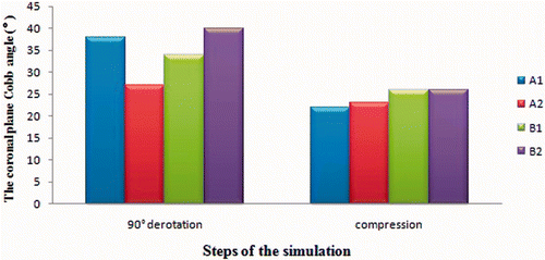
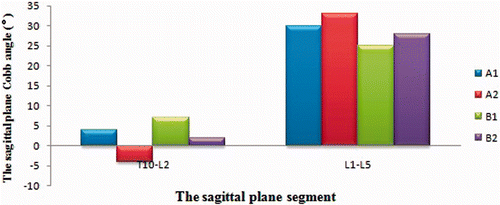
Results: With the four different surgical protocols, the coronary lumbar deformity was corrected to 22°, 23°, 26° and 26°, respectively, and a physiological sagittal configuration was maintained; however, higher stress was observed with solutions A1 (screw model implanted in the convex side of T12-L3) and A2 (screw model implanted in the convex side of T11-L4), while solution B2 (the posterior approach: T10-L5, fusion to SV) lost too many lumbar movement segments. A similar apical rotational correction was recorded (41.68° and 37.79°) for solutions A2 and B1 (the posterior approach: T10-L4, fusion to LEV), which both instrumented the lower end vertebrae.
Conclusions: The presented model could be used successfully to simulate correction procedures, including 90° derotation and compression, for the first time. The Lenke 5 AIS in this particular case was more rigid, and solution B1 was considered the ideal choice for treatment of this patient.
Introduction
To address the lack of a reliable, universally acceptable classification system for adolescent idiopathic scoliosis (AIS), in 2001 Lawrence G. Lenke established a new classification system for AIS that is both reliable and universally accepted. The definition of Lenke 5 AIS is that the thoracolumbar/lumbar curve is the major curve and is structural, while at the same time the proximal thoracic and main thoracic curves are nonstructural Citation[1]. Traditionally, the treatment options for AIS have included exercises, in-patient rehabilitation, and braces and surgery Citation[2].
Surgical correction options for Lenke 5 AIS can be divided into anterior and posterior corrections using different surgical approaches. Anterior correction with short segment fusion and better derotation effect has been the classic method for treating Lenke 5 AIS, but the third generation of posterior correction instrumentation has stronger orthopedic force compared with the first and second generations. The newly developed segmental pedicle screw technique with better derotation could have significant capability for positioning the distal vertebral body close to the midline, and making an unstable vertebral body enter stable areas Citation[3], thereby achieving better correction results with fewer fusion segments.
In 1986, Viviani et al. Citation[4] first described a two-dimensional model, based on the establishment of a linear finite element method, for the analysis of the internal fixation rate with respect to the size of the deformity. There have since been additional reports of AIS orthopedic finite element simulation Citation[5–9]. In this paper, the establishment of a finite element model of AIS based on a Lenke 5 patient was simulated by four different programs using either the anterior or posterior correction approach, with a view to obtaining more guidance as to the best surgical approach. The different programs and the orthopedic spine were compared preliminarily with respect to the stress levels to determine the ideal surgical treatment choice for this case.
Materials and methods
Model settings
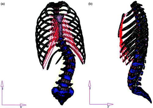
Thin spinal CT images (slice thickness 1 mm; layer spacing 1 mm) of a 15-year-old female Lenke type 5 AIS patient were acquired after obtaining consent, and Mimics 10.01 (Materialise NV, Leuven, Belgium) and HyperWorks 8.0 (Altair Engineering, Inc.) were used to create the three-dimensional finite element model Citation[10], Citation[11] ().
Model parameter optimization and validation
This phase involved using the model to simulate the bending test Citation[12] and, neglecting the interaction, analyzing the orthogonal design method for four factors and three levels with SPSS 11.0 Citation[13]. The parameters of the disc material properties and the cortical bone thickness of the upper thoracic vertebrae (T1-T5), thoracic scoliosis (T5-T11), lumbar scoliosis and three other regional segments were optimized. The supine position lateral bending test, standing test, and sectional loaded test were simulated to verify the validity of the parameter-optimized model Citation[12].
Construction of a screw-rod system finite element model
The four-screw-rod finite element models (both anterior and posterior) were constructed directly in Hypermesh (). An ideal bonding interface was adopted for the interface between the screw and spine, restricting all degrees of freedom in the interface of the vertebrae and screw. The interface between the screw and rod was defined as the surface-to-surface contact, and column articulations were created in the centers of the screw and rod. The screws and rods are made of titanium, whose elastic modulus and Poisson's ratio are 110 000 MPa and 0.3, respectively.
Figure 2. The finite element model of the anterior screw-rod system. An ideal bonding interface was adopted for the interface between the screw and the spine, restricting all degrees of freedom in the interface of the vertebrae and screw. The interface between the screw and rod was defined as the surface-to-surface contact, and column articulations were created in the centers of the screw and rod.
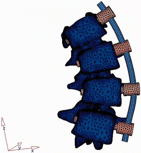
The first-forming shape of the rods was determined by the postoperative lumbar lordosis angle, because the patient's preoperative lumbar scoliosis was 52° according to the supine position X-ray. It was only necessary to rotate the rods 90° to satisfy the physiological lumbar lordosis, thus the correction rod curvature was the arc shape formed by the connection of the screw tail nodes.
Preoperative process for the model
Simulation of approaches A1 and A2 (the anterior approach) entailed removing the scoliosis convex-side semi-disc and the anterior longitudinal ligament in the scoliosis fusion region of the model, while retaining the concave-side anterior longitudinal ligament and the fibrous rings, to mimic the anterior discectomy performed in the actual surgery. Simulation of approaches B1 and B2 (the posterior approach) entailed removing the scoliosis convex-side ligamentum flava, the interspinous and supraspinous ligaments, and the capsular ligament of the zygapophyseal joints in the scoliosis fusion region of the model to mimic the posterior release operation performed in the actual surgery.
Simulation of orthopedic surgery
Considering the patient position, anesthesia, surgical dissection and other factors during orthopedic correction, maintenance of the stability of the spine has depended mainly on the internal structure, i.e., the intervertebral discs and ligaments. Therefore, the finite element ignores the role of muscle force and gravity. The simulation of the orthopedic correction process comprises three steps: a 90° derotation, compression, and locking. The LS-DYNA Solver (Livermore Software Technology Corporation) was used for conditional calculation, with HyperView (Altair Engineering, Inc.) being used for post-process analysis and results output.
Simulation of A1 and A2 orthopedics
For this simulation, all degrees of freedom of the S1 vertebral body were fixed, and those in the Y direction for the T1 vertebral body were limited. After the constructed screw model had been implanted in the convex side of the T12-L3 (solution A1) or T11-L4 (solution A2) vertebral body, the first-forming rods were installed in the end of the screw. The three steps of the simulation of the orthopedic correction process were performed as follows:
Simulation of the 90° derotation process. This simulated the function of the surgical clamp during the operation by generating a handle on the rods, and then simulated the rod rotation by exerting rotational torque on the handle, making the orthopedic rod rotate through 90° to the convex side, which turned the scoliosis in the coronal plane into lumbar physiological lordosis in the sagittal plane. During the rotation process, the end of the screw can freely move along and rotate around the rods.
Simulation of the compression process. After simulation of the rod rotation, the upper and lower fixed vertebral levels were ensured as far as possible, exerting a load on the vertebral screw end to narrow the distance between the screws, and thereby simulate the compression process, until the upper and lower laminae terminales of the intervertebral space were nearly parallel.
All the screw-rod motions were locked without orthopedic effect.
Simulation of B1 and B2 orthopedics
For Lenke 5 AIS, during the posterior derotation correction, the peak-value load was only generated from the convex-side orthopedic screws and rods, while the concave-side orthopedic rod represented only a secondary stiffness with a minor role in the correction Citation[14–15]. During the simulation of derotation, the concave-side orthopedic rod can exert an effect on the interface stress between the screws and bones, so the model of the B1/B2 correction complex only included the convex side.
T1 and S1 movement in the Y direction (i.e., vertically in the plane of the operating table) was limited to simulate the contact between the prone patient and the operating table.
After the constructed screw model had been implanted in the convex side of the vertebral body in the fusion region, the first-forming rods were installed in the end of the screw. During simulation of the 90° derotation process, a certain rotational torque was exerted simultaneously on the convex side at the end of each screw to simulate direct vertebral derotation. The posterior correction of fusion to lower end vertebrae (LEV) (T10-L4, solution B1) and fusion to SV (T10-L5, solution B2) were both stimulated.
Observation index
Measurements included the main scoliosis Cobb angle on the coronal plane after each orthopedic procedure, the angulation of the thoracolumbar junction, lumbar spine and other parts in the sagittal plane, the angle of apical vertebral rotation (Aaro method), and other indices of clinical concern, as well as the change in stress at the interface between the screws and spine after correction.
Results
Scoliosis correction in coronal and sagittal planes
The four alternative solutions yielded almost identical results for the final scoliosis correction of deformity in the coronal plane (), and the normal curvature in the sagittal plane (T10-L2, T12-L5) could be maintained ().
Correction of apical vertebral rotation
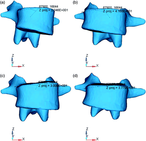
The Aaro method was used to measure the rotation correction angles for the L2 vertebra in A2 and B1 (). The correct angles for the apical vertebrae were 20.46° and 30.19°, respectively, after the rod rotation, and the final angles were 41.68° and 37.79°, respectively, after compression.
Figure 5. Measurement of the L2 vertebral rotation correction angle. (a) The correct angle of the apical vertebrae was 20.46° after rotating the rod in A2. (b) The final angle after compression was 41.68° for A2. (c) The correct angle of the apical vertebrae was 30.19° after rotating the rod in B1. (d) The final angle after compression was 37.79° for B1.
Spine stress distribution after orthopedic treatment
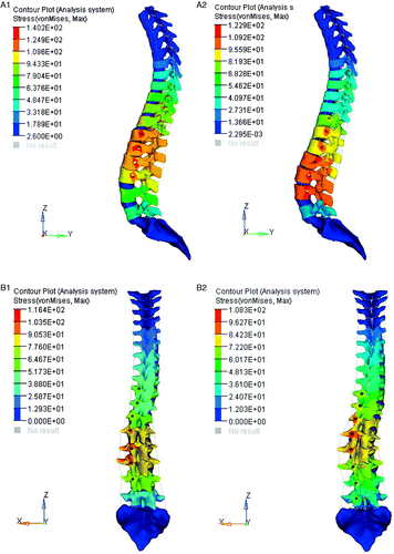
The final stress distribution of the spine after the orthopedic treatment is shown in . With solution A1, the stress in most regions around the screw holes was more than the ultimate strength of bone (120Mpa Citation[16]), reaching a maximum value of 140 Mpa, but with the other three solutions the stress exceeded the ultimate strength of bone for only a few nodes.
Figure 6. Final spine stress distribution for the four solutions after the orthopedic correction procedure. The stress on most regions around the screw holes with solution A1 was greater than the ultimate strength of bone (120 Mpa), but with the other three solutions only a few nodes had stress exceeding this value.
Discussion
Surgical treatment of Lenke 5 AIS
There are two principles for choosing the correct fusion segment in the anterior approach: Zielke's end–end principle and Hall's short segment fusion. Hall's method applies exclusively to patients with thoracolumbar/lumbar scoliosis which is not severe and who still have good flexibility (flexibility > 50%).
The traditional posterior correction is required to fuse to the stable vertebra if the Harrington instrumentation system is used. However, the third generation of posterior correction instrumentation has more orthopedic force than the first and second generations, especially with regard to the segmental pedicle screw technique, which can penetrate the anterior, middle or posterior column and is more capable than the hook-rod system in 3D correction, in terms of positioning the distal vertebral body close to the midline and making an unstable vertebral body enter a stable area intraoperatively Citation[3], and involves fewer fusion segments. Several other groups Citation[17–23] have treated thoracolumbar/lumbar AIS with pedicle screw fixation, making the distal vertebral fusion become end vertebral or neutral vertebral fusion with good correction effects.
Features of Lenke 5 AIS derotation
Existing biomechanical data show that the disc excision in the fusion region in the anterior approach weakens resistance against lumbar rotation, but improves derotation of the implant Citation[24]. Also, anterior instruments operate directly on the anterior vertebral body with ventral derotation by pressing the vertebrae, which leads to good derotation effects.
Pedicle screws penetrating the anterior, middle or posterior columns to the front of the vertebrae can transmit orthopedic force from the back to the front of the vertebrae; the direction in which the orthopedic rod is made to rotate through 90° in the convex side is opposite to the direction of vertebral body rotation, and the friction force between the screw and rod is helpful for orthopedic rotation. The full-segment pedicle screw with more fixed points can make vertebral derotation correction directly by rotation of the apical vertebrae and of the pedicle screw near the apical vertebrae. Many reports [see references Citation[20], Citation[25–28] have demonstrated that pedicle screw fixation achieves good results for rotational deformity corrections. In 2004 Lee et al. Citation[26] proposed that, after rotating the rod using a pole rotation instrument connected to the end of the screw, “direct vertebral derotation” resulted in further improvement in the correction of rotation in the posterior approach.
In this study, during simulation of a 90° derotation process, a certain rotational torque was exerted simultaneously on the convex side at the end of each screw to simulate direct vertebral derotation. By measuring the derotation effect of solutions A2 and B1, it was found that both solutions resulted in satisfactory rotation correction.
Interface stress analysis
In this study, the Mises stress value of the interface between the screw and bone represented the occurrence of vertebral pedicle wall fracture or the possibility of bone damage when simulating the 90° derotation process and the compression process in both the anterior and posterior approach. With higher stress values, the possibility of invading the spinal canal increases.
The four simulation solutions yielded almost identical correction results. However, in the orthopedic stress test, the stress on most regions around the screw holes with solution A1 exceeded the ultimate strength of bone (120 Mpa) (), resulting in a higher risk of loosening for the screws due to spinal fractures, thereby leading to fixation failure. Factors contributing to this were the over-concentration of stress resulting from the smaller number of fixed points in anterior short segment fusion and the stronger force involved, and that the scoliosis in this particular Lenke 5 AIS case was more rigid (flexibility was 36.7% on the concave side of the bending imaging, i.e., the angle formed by the connecting line of the L4 vertebral body and the spina iliaca was approximately 14°), which contrasts with the guiding principles for short segment fusion (where general requirements for flexibility are >50%). Solution B2 lost too many lumbar movement segments. Solutions A2 and B1 had the same lower fixed vertebrae and had similar vertebral stress levels after the orthopedic correction procedure, but solution B1 only simulated the screws and rods on the convex side, whereas the stability rod on the concave side can also provide support. A posterior approach with more fixed points can reduce the stress on the screw. In this study, solution B1 was considered to be the ideal choice for treatment of this Lenke 5 AIS patient.
Declaration of interest: The study was supported by grants from the Hunan Province Institute of Science and Technology Fund (2009SK2012) and the Fundamental Research Funds for the Central Universities (2012QNZT126).
References
- Lenke LG, Betz RR, Harms J, Bridwell KH, Clements DH, Lowe TG, Blanke K. Adolescent idiopathic scoliosis: a new classification to determine extent of spinal arthrodesis. J Bone Joint Surg Am 2001; 83-A(8)1169–1181
- Weiss HR, Goodall D. The treatment of adolescent idiopathic scoliosis (AIS) according to present evidence. A systematic review. Eur J Phys Rehabil Med 2008; 44(2)177–193
- Wang JL, Parnianpour M, Shirazi-Adl A, Engin AE, Li S, Patwardhan A. Development and validation of a viscoelastic finite element model of an L2/L3 motion segment. Theor Appl Fract Mech 1997; 28: 81–93
- Viviani GR, Ghista DN, Lozada PJ, Subbaraj K, Barnes G. Biomechanical analysis and simulation of scoliosis surgical correction. Clin Orthop Relat Res 1986; 208: 40–47
- Lafage V, Dubousset J, Lavaste F, Skalli W. 3D finite element simulation of Cotrel-Dubousset correction. Comput Aided Surg 2004; 9: 17–25
- Dumas R, Lafage V, Lafon Y, Steib JP, Mitton D, Skalli W. Finite element simulation of spinal deformities correction by in situ contouring technique. Comput Method Biomec 2005; 8: 331–337
- Lafon Y, Steib JP, Skalli W. Intraoperative three dimensional correction during in situ contouring surgery by using a numerical model. Spine 2010; 35: 453–459
- Rohlmann A, Richter M, Zander T, Klöckner C, Bergmann G. Effect of different surgical strategies on screw forces after correction of scoliosis with a VDS implant. Eur Spine J 2006; 15: 457–464
- Wang Z-Y, Liu Z-D, Wang Z, Wang D-M, Wang C-T, Li X-F. Research on biomechanics of the adolescent idiopathic scoliosis treated by the ventral derotation spondylodesis (VDS). Chin J Experimental Surg 2007; 24: 669–671
- Zhang H-Q, Guo C-F, Chen L-Q, Liu S-H, Tang M-X, Chen J. Establishment and validation of 3-dimensional finite element model of Lenke 1 BN idiopathic scoliosis. Chin J Orthopaedics 2010; 30: 768–772
- Tang M-X, Zhang H-Q, Wang Y-F, Zhao D, Liu S-H, Chen L-Q, Guo C-F, Wang Y-X. Predict therapeutic efficacy of brace for adolescent idiopathic scoliosis using finite element method. J Spinal Surg 2010; 8: 108–113
- Wang Z-Y, Liu Z-D, Wang Z, Wang C-T, Ming YE, Li X-F. Development of finite element model for the scoliotic spine and its parameters optimization. Beijing Biomed Eng 2008; 27: 28–32
- Wang R-X. Mathematical Statistics. Xi’an Jiao Tong University Press, Xi’an 2006; 150–160
- Aubin C-E, Petit Y, Stokes IAF. Biomechanical modeling of posterior instrumentation of the scoliotic spine. Comput Method Biomec 2003; 6: 27–32
- Majdouline Y, Aubin CE, Sangole A, Labelle H. Computer simulation for the optimization of instrumentation strategies in adolescent idiopathic scoliosis. Med Biol Eng Comput 2009; 47: 1143–1154
- Tang H, Chen H, Luo X-Z. Research progress in biomechanics of bone mineral intensity. Chin J Trauma 2005; 21: 952–954
- Halm H, Niemeyer T, Link T, Liljenqvist U. Segmental pedicle screw instrumentation in idiopathic thoracolumbar and lumbar scoliosis. Eur Spine J 2000; 9: 191–197
- Shufflebarger HL, Geck MJ, Clark CE. The posterior approach for lumbar and thoracolumbar adolescent idiopathic scoliosis: posterior shortening and pedicle screws. Spine 2004; 29(3)269–276
- Wang Y, Fei Q, Qiu G, Lee CI, Shen J, Zhang J, Zhao H, Zhao Y, Wang H, Yuan S. Anterior spinal fusion versus posterior spinal fusion for moderate lumbar/thoracolumbar adolescent idiopathic scoliosis. Spine 2008; 33: 2166–2172
- Qiu G-X, Wang Y-P, Fei Q, Shen J-X, Zhang J-G, Zhao H, Zhao Y, Zhao D, Li J-Y. Anterior spine fusion versus posterior spine fusion with pedical screws for lumbar and thoracolumbar adolescent idiopathic scoliosis. Chin J Orthop 2007; 27: 743–747
- Yu B, Wang Y-P, Qiu G-X, Zhang J-G, Shen J-X, Li Q-Y, Yang X-Y, Zhao L-J. Comparison of correction outcomes after anterior or posterior approach with lowest end vertebra instrumentation in adolescent idiopathic thoracolumbar/lumbar scoliosis. Natl Med J China 2009; 89: 2621–2621
- Li M, Gu SX, Zhu XD, Yang J-D, Zhang Q, Zhao Y-F, Wu D-J, Wang J-J, Ni J-Q, Yang X-M, Cao H-H. Use of posterior pedicle instrumentation on lumbar and thoracolumbar adolescent idiopathic scoliosis. Chin J Spine Spinal Cord 2007; 17: 261–265
- Monney G, Kaelin AJ. Short posterior fusion for patients with thoracolumbar idiopathic scoliosis. Clin Orthop 1999; 364: 32–39
- Chen B-H (translator). Biomechanics of scoliosis three-dimensional correction [M]. In: Hu Y-G (main translator). Spine Surgery. First edition. Beijing: People's Medical Publishing House; 2000. pp 158–164.
- Akçali O, Alici E, Koşay C. Apical instrumentation alters the rotational correction in adolescent idiopathic scoliosis. Eur Spine J 2003; 12: 124–129
- Lee SM, Suk SI, Chung ER. Direct vertebral rotation: a new technique of three-dimensional deformity correction with segmental pedicle screw fixation in adolescent idiopathic scoliosis. Spine (Phila Pa 1976) 2004; 29(3)343–349
- Fu G, Kawakami N, Goto M, Tsuji T, Ohara T, Imagama S. Comparison of vertebral rotation corrected by different techniques and anchors in surgical treatment of adolescent thoracic idiopathic scoliosis. J Spinal Disord Tech 2009; 22: 182–189
- Laohacharoensombat W, Jaovisidha S, Wajanavisit W, Suppaphol S. Apical derotation in the treatment of idiopathic scoliosis. J Med Assoc Thai 2005; 88: S58–S64
