
Abstract
Arthrodesis of the first metatarsophalangeal (MTP-1) joint is a widely used procedure for the treatment of hallux valgus in patients with MTP-1 degeneration, severe or recurrent deformity, or inflammatory arthritis. In this case, ten years earlier, the patient’s MTP-1 joint had been fused in a severe pronation deformity position. Subsequently, a laterally shifted tibial sesamoid and osseous rising of the phalanx base caused painful callosities. To correct the pronated deformity accurately, a custom-made surgical guide based on a three-dimensional computer tomography (3D-CT) simulation system was used. After correction of the deformity, the MTP-1 joint was again fused. Adequate correction was achieved, and the patient no longer complains of pain and can perform full weight-bearing on the forefoot. The difficulty and importance of placing the MTP-1 joint in an adequate rotational position in MTP-1 joint arthrodesis surgery were confirmed, as was the utility of 3D evaluation and a custom-made surgical guide for rotational adjustment between the metatarsal and the proximal phalanx. We believe that this system should be one of the indicators for adjusting the rotation, especially in revision MTP-1 joint fusion surgery.
Introduction
First metatarsophalangeal (MTP-1) joint arthrodesis is a widely accepted method for the surgical treatment of hallux (big toe) valgus deformity in patients with MTP-1 joint degeneration [Citation1–5]. In addition, this procedure can be used for patients with more severe deformities or recurrent hallux valgus, or with a deformity secondary to inflammatory arthritis of the joint [Citation6–10]. If the MTP-1 joint is fused in malposition, pain and functional problems occur. The recommended hallux valgus angle is between 20° and 30° [Citation11, Citation12]. Although the hallux valgus angle has not been shown to correlate with the clinical results [Citation13], it may be a determinant of the development of arthritis in the interphalangeal joint [Citation11].
Various authors have proposed values of hallux dorsiflexion from 0 to 40° [Citation12, Citation14–18]. These values can be somewhat misleading in that a plane of reference is not given. In determining dorsiflexion angles of the hallux in relationship to the horizontal surface of the ground, there may be difficulty in duplicating this angle in a non-weight-bearing foot on the operating room table. As mentioned above, many authors suggest varying degrees of valgus and toe dorsiflexion, while it has been reported that the proper reference point for the rotation angle is 0° [Citation19].
Rotation of the hallux results in undue pressure along either nail border, keratosis along a prominent medial or lateral condyle, or increased weight-bearing stress through the interphalangeal (IP) joint. Surgeons are told that, intraoperatively, they should use the nail plate as a guide to the degree of rotation present at the hallux. However, in the present case, the MTP-1 joint was fused in a severely pronated, rotated position, though angulation of the nail plate was used as a guide for rotation adjustment, suggesting the difficulty of achieving accuracy with this method. Angulation of the nail plate is varied by the flexibility of the IP joint, suggesting this guide is not always correct. It was therefore thought important that guides without a striding IP joint should be developed and used to avoid errors in determining the position of the distal phalanx bone and/or nail plate.
The shape of the bone surface and the pronation deformity of the MTP-1 joint differs between cases. Therefore, use of a patient-specific cutting and rotational guide for the first metatarsal and first proximal phalangeal bone was considered appropriate. This system was originally developed as a simulation system consisting of a 3D computer program and a custom-made osteotomy template that allows the reproduction of a preoperative simulation during the actual surgery for correction of fracture malunion and deformity [Citation20–24]. In the present case, this pronated deformity was evaluated three-dimensionally, and arthrodesis was performed in the re-aligned position after corrective osteotomy using a custom-made surgical guide.
Case report
A 64-year-old woman with a 31-year history of rheumatoid arthritis (RA) (functional class II, radiographic stage IV) had been treated with methotrexate (MTX, 4 mg/wk) and tocilizumab (8 mg/kg). Ten years earlier, at another hospital, MTP-1 joint arthrodesis and resection arthroplasty of the lesser toes had been performed for forefoot deformity with painful hallux valgus deformity and callosities. However, the hallux pain remained, and painful callosities formed. Four years later, at the same hospital, a partial resection of the osseous rising of the medial base of the proximal phalanx was performed, and extensor hallucis longus (EHL) elongation was also done for hyperextension of the IP joint. However, the hallux pain did not disappear, and the painful callosities remained ( and ). Subsequently, the deformity of the fused MTI-1 joint was evaluated three-dimensionally at our hospital. It was found that there was a severely pronated position of the proximal phalanx against the metatarsal (approximately 70° pronated) (), with subsequent lateral shifting of the tibial sesamoid and osseous rising of the proximal phalanx base that caused painful callosities (). Given these findings, it was decided to operate to correct the pronated deformity. After correction of the deformity, the MTP-1 joint was again fused as mentioned below. The patient no longer complains of pain and can perform full weight-bearing to the forefoot. The gait speed has increased, and the callosities have become smaller.
Figure 1. Preoperative X-ray of the affected foot. The MTP-1 joint is fused in malposition (yellow arrow). The X-ray shows the internal rotation of the proximal phalanx (white arrow), and the sesamoid bone is laterally shifted (blue arrow) (Hardy grade 4).
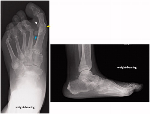
Figure 2. The affected foot. The laterally shifted tibial sesamoid and osseous rising of the proximal phalanx base have caused painful callosities (yellow arrows).
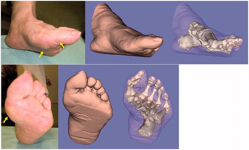
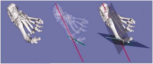
Figure 3. Three-dimensional evaluation of the affected foot. The severely pronated position of the proximal phalanx against the metatarsal (approximately 70° pronated) is evident.
Simulation technique
The affected limb (from the ankle to the forefoot) was scanned using a computed tomography scanner (LightSpeed Ultra 16, General Electric, Waukesha, WI), with scan time of 0.5 s, scan pitch of 0.562:1, tube current of 10 to 50 mA, and tube voltage of 120 kV. Digital data from 1-mm slices were sent to a workstation (Precision Workstation 650, Dell, Round Rock, TX). The skin and bones of the affected foot were segmented, and 3D surface models were constructed by applying 3D surface generation of the cortex of the bone and skin using an original computer program based on the Visualization Toolkit (Kitware, Clifton Park, NY).
Design and manufacture of the custom-made osteotomy guide
To reproduce the preoperative simulation during the actual surgery, an operative method using a custom-made osteotomy template was designed based on preoperative 3D computer simulation using commercially available software (Magics RP, Materialise, Leuven, Belgium). This was embodied as a plastic model through rapid prototyping technology (Eden 250, Objet Geometries, Rehovot, Israel, or Viper si2, 3D Systems, Rock Hill, SC) using medical-grade resin. The custom-made osteotomy template had a shape that closely fitted the bone surface and an osteotomy surface and drill-holes that guided the insertion of the Kirschner wires (K-wires). These K-wires were perpendicular to the longitudinal axis and horizontal plane of the metatarsal and proximal phalanx ( and ), and served intraoperatively as a rotational guide by parallelizing each other. The simulation for setting of the metatarsal and proximal phalanx cutting template is shown in . The projections given were programmed to guide the bone saw in cutting the metatarsal and proximal phalanx perpendicular to the longitudinal axis ().
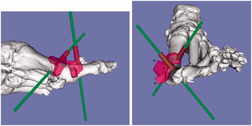
Figure 4. The simulation for setting the metatarsal and proximal phalanx cutting templates (red). The K-wires (green) are perpendicular to the longitudinal axis of the metatarsal and proximal phalanx. The projections given were programmed to guide the bone saw in cutting the metatarsal and phalanx perpendicular to the longitudinal axis (*).
Surgical technique
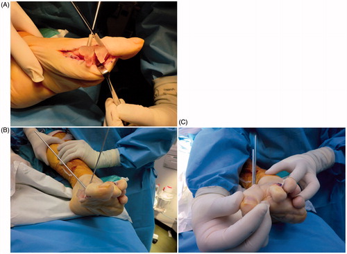
The tourniquet was inflated to 250 mm Hg and surgery was carried out through a previous skin incision. After the incision, subcutaneous soft tissue was retracted, and the periosteum was split, exposing the bone surface. Preparation of the osseous surfaces commenced with a flat resection of the distal end of the metatarsal and the proximal end of the proximal phalanx, which was carried out with the aid of the 3D-CT-based custom-made surgical guides designed preoperatively () and fixed with the K-wires. Next, the guide was broken and removed while leaving the K-wires in place. The rotational position between the two bones was then adjusted using the fixed K-wires, which served as a rotational guide by parallelizing each other (). After confirmation of sufficient and adequate correction, the MTP-1 joint was re-fixed with two 3-mm cannulated screws and an AcuTwist® screw. The duration of non-weight-bearing was 4 weeks, after which the patient was allowed to do full weight-bearing with an insole.
Figure 5. Intraoperative photograph of the custom-made surgical guide fixed with K-wires. (A, B) The distal end of the metatarsal and the proximal end of the proximal phalanx are fixed with K-wires with the aid of the 3D-CT-based custom-made surgical guide designed preoperatively. (C) The rotational position between the two bones is adjusted using the fixed K-wires as a rotational guide.
Discussion
Though it is very important to fix the MTP-1 joint in an appropriate position, with the appropriate hallux valgus angle, dorsiflexion angle, and rotation angle between the metatarsal and proximal phalanx bone, this is not always easy. In fact, the present case showed a proper hallux valgus angle and appropriate hallux dorsiflexion, but the rotation angle was not acceptable, suggesting the limitation and difficulty of achieving accuracy with this method using the nail plate as a guide for rotational adjustment. An alignment gauge has been designed specifically for use in metatarsophalangeal fusion surgery, indicating the importance of having a guide available to provide an accurate index of rotation and alignment. Furthermore, surgeons are told that, intraoperatively, they should use the nail plate as a guide to the degree of rotation present at the hallux. However, angulation of the nail plate is varied by the flexibility of the IP joint, suggesting that this guide is not always correct. It was therefore thought to be important that guides without a striding IP joint should be developed and used to avoid errors in determining the distal phalanx bone and/or nail plate position (rotation).
In the current case, a custom-made surgical guide without a striding IP joint was used ( and ). In the process of making the guide, 3D evaluation of the deformity can be performed, because this guide is based on a 3D-CT simulation system. As shown in the simulation picture, one can clearly recognize the severely pronated deformity of the fused MTP-1 joint and the laterally shifted tibial sesamoid which causes the painful callosity preoperatively ( and ). One can also see that the rotational deformity was corrected, and that the subsequent repositioning of the sesamoid was appropriate postoperatively ( and ). In such surgery, it is difficult to identify an adequate starting position and the direction of bone cutting because the MTP-1 joint is already fused, so landmark information is poor. In such cases, a pre-made custom guide is very useful ( and ). We found it easier to perform the procedure using the guide, because there was no confusion about the bone cutting. When using this guide for surgery, however, removal of soft tissue from the surface of the bone is very important, because remaining soft tissue causes an insufficient fit between the guide and the bone surface, so that bone cutting becomes rough and inaccurate. After the osteotomy, the K-wires used for fixation of the guide are very useful, because they can serve as an indicator for rotational adjustment by parallelizing each other ().
Figure 6. Postoperative X-ray of the affected foot. The MTP-1 joint is re-fused in the proper rotational position. Improvements in the pronated deformity and the sesamoid position are seen (Hardy grade 2).
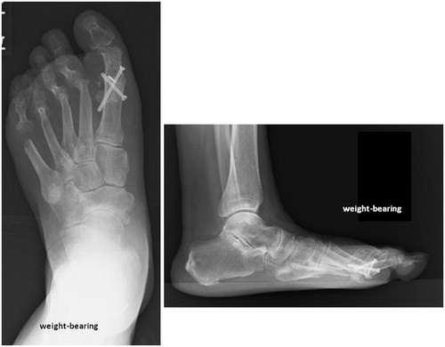
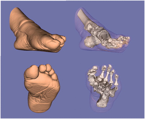
Figure 7. Images created from the 3D-CT data of the affected foot postoperatively. The rotational deformity is corrected, and the sesamoid is properly repositioned postoperatively.
It is thought that revision surgeries of MTP-1 joint fusion will increase in the future. A custom-made surgical guide is not always necessary in MTP joint fusion surgery, but it provides surgeons with an accurate indicator in revision surgery. In the future, we plan to increase the number of cases, and re-evaluate the approach. Furthermore, we want to make such a custom-made guide more commercially available. To realize this concept, a fully controlled and tested system, manufacture’s support, and the augmentation of education for technical assistance will be important.
Conclusion
In the present case, the difficulty and importance of adequate rotational positioning in MTP-1 joint fusion were reconfirmed. Furthermore, it is very important and useful to perform three-dimensional evaluation preoperatively, and then to use a custom-made surgical guide for rotational adjustment. We believe that this system should be one of the indicators for adjusting the rotation, especially in revision MTP-1 joint fusion surgery.
Declaration of interest
One of the authors (Tsuyoshi Murase) has received funding in support of this research from JST (Japan Science and Technology Agency).
Acknowledgements
The authors would like to thank Nakashima Medical Co. Ltd. and Ryoji Nakao (Department of Orthopedic Biomaterial Science, Osaka University Graduate School of Medicine) for their excellent technical assistance.
References
- Coughlin M. Hallux valgus. 1997. Instr Course Lect 46:357–91
- Coughlin MJ, Grebing BR, Jones CP. 2005. Arthrodesis of the first metatarsophalangeal joint for idiopathic hallux valgus: Intermediate results. Foot Ankle Int 26:783–92
- DeFrino PF, Brodsky JW, Pollo FE, Crenshaw SJ, Beischer AD. 2002. First metatarsophalangeal arthrodesis: A clinical, pedobarographic and gait analysis study. Foot Ankle Int 23:496–502
- Mann RA, Oates JC. 1980. Arthrodesis of the first metatarsophalangeal joint. Foot Ankle 1:159–66
- Politi J, Hayes J, Njus G, et al. 2003. First metatarsophalangeal joint arthrodesis: A biomechanical assessment of stability. Foot Ankle Int 24:332–7
- Coughlin MJ. 2000. Rheumatoid forefoot reconstruction. A long-term followup study. J Bone Joint Surg Am 82:322–41
- Grimes JS, Coughlin MJ. 2006. First metatarsophalangeal joint arthrodesis as a treatment for failed hallux valgus surgery. Foot Ankle Int 27:887–93
- Mann RA, Thompson FM. 1984. Arthrodesis of the first metatarsophalangeal joint for hallux valgus in rheumatoid arthritis. J Bone Joint Surg Am 66:687–92
- Pinney SJ, Song KR, Chou LB. 2006. Surgical treatment of severe hallux valgus: The state of practice among academic foot and ankle surgeons. Foot Ankle Int 27:1024–9
- Sammarco GJ, Idusuyi OB. 2001. Complications after surgery of the hallux. Clin Orthop Relat Res 391:59–71
- Fitzgerald JAW. 1969. A review of long term results of arthrodesis of the first metatarsophalangeal joint. J Bone Joint Surg Br 51:488–93
- Smith RW, Joanis TL, Maxwell PD. 1992. Great toe metatarsophalangeal joint arthrodesis: a user friendly technique. Foot Ankle 13:367–77
- Mann RA, Schakel ME 2nd 1995. Surgical correction of rheumatoid forefoot deformities. Foot Ankle Int 6:1–6
- McKeever D. 1952. Arthrodesis of the first metatarsophalangeal joint for hallux rigidus and metatarsus primus varus. J Bone Joint Surg 34:129–34
- Marin G. 1960. Arthrodesis of the first metatarsophalangeal joint for hallux valgus and hallux rigidus. Guy’s Hosp Rep 109:174–78
- Harrison MHM, Harvey FJ. 1963. Arthrodesis of the first metatarsophalangeal joint for hallux valgus and rigidus. J Bone J Surg 45A:471–80
- Marin G. 1968. Arthrodesis of the first metatarsophalangeal joint for hallux valgus and hallux rigidus: a new method. Int Surg 50:175–80
- Lipscomb PR. 1979. Arthrodesis of the first metatarsophalangeal joint for severe bunions and hallux rigidus. Clin Orthop Relat Res 142:48–54
- Calise DA, Man P, Hetherington VJ. 1994. Arthrodesis of the first metatarsophalangeal joint. In: Hetherington VJ, editor. Textbook of Hallux Valgus and Forefoot Surgery. New York: Churchill Livingstone. pp 267–77
- Murase T, Oka K, Moritomo H, et al. 2008. Three-dimensional corrective osteotomy of malunited fractures of upper extremity with use of a computer simulation system. J Bone Joint Surg Am 90:2375–89
- Oka K, Moritomo H, Goto A, et al. 2008. Corrective osteotomy for malunited intra-articular fracture of distal radius using a custom-made surgical guide based on three-dimensional computer simulation: case report. J Hand Surg 33A:835–40
- Moritomo H, Murase T, Goto A, et al. 2002. The usefulness of three dimensional computer simulation for surgical treatment of malunited fracture and nonunion of upper extremities [In Japanese]. J Jpn Soc Surg Hand 19:252
- Murase T, Moritomo H, Goto A, et al. 2005. Does three-dimensional computer simulation improve results of scaphoid nonunion surgery? Clin Orthop Relat Res 434:143–50
- Murase T, Moritomo H, Sugamoto K, et al. 2005. 3D computer simulation for deformity correction of the limb [In Japanese]. Orthop Surg Traumatol 48:1055–60