
Abstract
Objective: This study presents and evaluates a semi-automated algorithm for quantifying malalignment in complex femoral shaft fractures from a single intraoperative cone-beam CT (CBCT) image of the fractured limb.
Methods: CBCT images were acquired of complex comminuted diaphyseal fractures created in 9 cadaveric femora (27 cases). Scans were segmented using intensity-based thresholding, yielding image stacks of the proximal, distal and comminuted bone. Semi-deformable and rigid affine registrations to an intact femur atlas (synthetic or cadaveric-based) were performed to transform the distal fragment to its neutral alignment. Leg length was calculated from the volume of bone within the comminution fragment. The transformations were compared to the physical input malalignments.
Results: Using the synthetic atlas, translations were within 1.71 ± 1.08 mm (medial/lateral) and 2.24 ± 2.11 mm (anterior/posterior). The varus/valgus, flexion/extension and periaxial rotation errors were 3.45 ± 2.6°, 1.86 ± 1.5° and 3.4 ± 2.0°, respectively. The cadaveric-based atlas yielded similar results in medial/lateral and anterior/posterior translation (1.73 ± 1.28 mm and 2.15 ± 2.13 mm, respectively). Varus/valgus, flexion/extension and periaxial rotation errors were 2.3 ± 1.3°, 2.0 ± 1.6° and 3.4 ± 2.0°, respectively. Leg length errors were 1.41 ± 1.01 mm (synthetic) and 1.26 ± 0.94 mm (cadaveric). The cadaveric model demonstrated a small improvement in flexion/extension and the synthetic atlas performed slightly faster (6 min 24 s ± 50 s versus 8 min 42 s ± 2 min 25 s).
Conclusions: This atlas-based algorithm quantified malalignment in complex femoral shaft fractures within clinical tolerances from a single CBCT image of the fractured limb.
Introduction
Femoral shaft fractures are commonly encountered in orthopaedic trauma and occur most frequently as a result of high-energy trauma in individuals under the age of 35 [Citation1]. Closed intramedullary (IM) nailing of the femur has become the standard of care for adults due to its high union rates, low complication rates and minimally invasive nature [Citation2]. Clinically, in complex comminuted fracture reduction, the two main fragments are normally aligned in anterior-posterior and medial-lateral translation and the angle between the long axes of the bones is then restored. Leg length and periaxial rotation are restored about a guidewire and nail. Fluoroscopic guidance enables the visualization of the fracture fragments; however, the resolution of these images and their 2D nature limit the ability to successfully align complex fractures in all six degrees of freedom (DOF).
Despite its popularity, complications relating to malalignment occur in IM nailing [Citation3–5]. Current clinical tolerances for alignment of femoral shaft fractures are 5–10° varus/valgus and 10° flexion/extension angulation, 15° periaxial rotation, and 1.0–1.5 cm leg length and medial-lateral and anterior-posterior translation [Citation6–9]. In some series, severe malalignments in excess of these tolerances have been reported in 19–30% of patients, leading to malunions [Citation2, Citation3, Citation10–12]. Fluoroscopy-based workflows combined with navigation have been used in femoral shaft fracture reduction with IM nailing [Citation13, Citation14]. Malalignment is determined with respect to landmarks on the contralateral limb and through manual digitization of the fracture fragments. These systems have achieved only variable results with respect to periaxial rotation [Citation13, Citation15]. Three-dimensional imaging in the form of cone-beam CT (CBCT) paired with flat-panel detectors can provide volumetric data from a series of projections obtained in a single rotation of a unit about a patient [Citation16]. CBCT offers the ability to obtain 3D data with sub-millimetric isotropic resolution and a large field of view. CBCT images enable the use of surface features and 3D-based analyses to guide fracture alignment.
The objective of this work was to develop and validate a semi-automated algorithm in which malalignment between superior and inferior fracture fragments is determined based on a single CBCT image of the injured femur. We hypothesized that an atlas-based approach would enable the quantification of the malalignment within clinical tolerances in 6 DOF, even in the presence of severe comminution. This study further aimed to compare the performance of a synthetic atlas (based on averaged anatomical data) with that of an atlas generated based on a single human femur.
Materials and methods
Atlas construction
Two atlases were created from CT scans performed on a GE LightSpeed VCT scanner (GE Corp., Fairfield, CT): a right intact synthetic femur (Pacific Research Laboratories Inc., Vashon, WA) and a left intact cadaveric femur (from a 50-year-old male with no visible pathology), both at a voxel size of 0.67 × 0.67 × 1.25 mm. Each atlas scan was imported into an image-analysis software platform (AmiraDEV 5.2, Visage Imaging, Berlin, Germany), segmented using intensity-based thresholding, and saved as an image stack that included only the voxels containing bone.
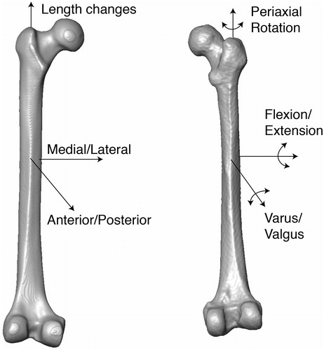
Each atlas was aligned so that the main anatomical axes were coincident with the Cartesian coordinates of the global image analysis system. A module within the AmiraDEV environment was used to calculate the three main axes of mass distribution; the axis with the smallest moment of inertia was defined as the z-axis of the atlas shaft and aligned to the global z-axis [Citation17]. Landmarks were then placed on the most posterior point of the femoral condyles using coronal slices and this axis was aligned with the global x-axis, again using the principal axes (). The medial-lateral (x), anterior-posterior (y) and longitudinal (z) translation, the flexion/extension (α) and varus/valgus (β) angulation, and the periaxial (φ) rotation angles could thus be used to describe malalignment in clinically relevant combinations of translations and rotations.
Figure 1. Isosurfaces of the synthetic (left) and cadaveric (right) atlases with the 6 DOF of malalignment labelled. Surface features on the synthetic atlas appear much smoother and less pronounced compared to those of the cadaveric atlas.
Fracture model and scan acquisition
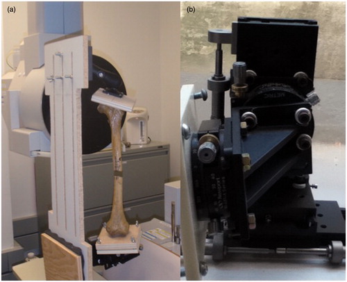
Nine dried cadaveric left femora with no visible pathology (Pacific Research Laboratories Inc.; no demographic data was available from the supplier) were obtained, stripped of soft tissue and mounted in a mechanical jig (). The jig was composed of a clamp mounted on a ball joint that enabled movement in 6 DOF to align the sample. The specimen was then secured at its distal end to a platform that had been mounted on a series of six mechanical stages (Newport Corporation, Irvine, CA) permitting translation (accurate to 0.05 mm) and rotation (accurate to 0.5°) about the x-, y- and z-axes.
Figure 2. (a) A dried femur specimen mounted in the jig and secured within the CBCT scanner. The proximal end is mounted to the ball joint and the distal end to the precision stages. (b) A close-up of the stages used to create the malalignment conditions.
Within the jig, a diaphyseal osteotomy was performed on each specimen, removing bone of various lengths (from 7.5 to 76 mm) to simulate fracture comminution. Removed segments of bone were measured using calipers accurate to 0.05 mm. Examination of markings placed on the bone ensured the two fragments initially maintained their neutral alignment positions within the jig. The comminuted bone fragment was malpositioned in the fracture gap. The jig was placed within the field of a CBCT scanner (CB MercuRay scanner, Hitachi Medical Systems America, Twinsburg, OH) and CBCT images were acquired of the specimens under random malalignments (voxel size 0.377 × 0.377 × 0.377 mm; field of view 30.5 cm; 80 kVp and 10 mA). Each bone was placed in three different configurations, leading to a total of 27 malaligned scans of 9 femora with 9 different fracture gaps (ranges are summarized in ). Longitudinal translation (z) of the distal fragment was performed to vary the length of the proximal and distal fragments that were visible within the field of view. Images were segmented using intensity-based thresholding and saved into three image stacks: the proximal/superior fragment, the comminution or fractured volume, and the distal/inferior fragment.
Table I. Ranges of medial-lateral translation (x), anterior-posterior translation (y), flexion/extension angulation (α), varus/valgus angulation (β), periaxial rotation (ϕ), and leg length (z) used to create the malalignment conditions.
Semi-automated registration
A semi-automated algorithm was written in Tool Command Language for AmiraDEV (run on an Intel Xenon 2 CPU 2.33 GHz with 8 GB RAM). is a flow chart outlining the main steps within the registration algorithm. The three image stacks were loaded into the software and the user was prompted to specify the fracture side. If the fractured femur was opposite to that of the atlas (left versus right), the atlas was mirrored about the z-axis. Isosurfaces of the fractured femur and the atlas were visualized in 3D and the atlas was roughly spatially aligned to the proximal fragment using a manual, interactive transform editor (9 DOF, allowing scaling, translational and rotational adjustments) to provide an initial estimate of its position with respect to the proximal fragment. Shearing was not included in the transformation of the atlas to ensure that the relationship between the principal axes and the global coordinate system remained constant. An interactive editor was used to crop the atlas so that it contained only the region overlapping the proximal fragment. The cropping step was included so that the affine registration did not attempt to align anatomical landmarks to areas in the full atlas scan not present in the scan of the fractured specimen and to decrease the time required for the registration.
Figure 3. Flow chart depicting the sequence of key actions in the algorithm. (a) Image stacks from the specimen and the atlas are loaded. (b) The atlas is manually aligned to the superior fragment (scaling, translation, and rotation) followed by (c) finer, automated registration. (d) The inferior fragment is manually aligned to the atlas (translation and rotation), and then (e) automatically registered, yielding medial-lateral and anterior-posterior translations, flexion/extension and varus/valgus angulations, and periaxial malrotation. Finally (f), the gap-bordering slices in the superior and inferior fragments are manually selected and the comminution volume is calculated based on the bony voxels present to estimate leg length.

Following cropping of the atlas, an automated affine registration with 9 DOF was performed allowing translation, rotation and anisoscaling of the atlas to best align it to the superior fragment [Citation17]. The registration initially downsampled both image sets by 8× in all directions to decrease the computational time required for the coarser transforms. Both images were then sequentially upsampled to perform finer transform steps until their initial resolution was restored, with a step length of 0.01 mm for fine tuning. The registration used a quasi-Newtonian optimization method to determine the final registration, relying on a normalized mutual information metric which was used to account for the differences in the image intensities arising from different imaging modalities, CBCT and CT, and resolutions [Citation18, Citation19]. Only voxels that had been included in the initial segmentation of both the atlas and the superior fragment were included in the registration.
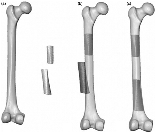
The inverse of the registration transform without the scaling factors was then calculated and applied to all image stacks (the full atlas, the proximal and distal fracture fragments, and the comminution volume). This aligned the atlas and proximal fragment with the global coordinate system. The center of the bone contained within the most distal slice (user-selected) of the proximal fragment was calculated based on its voxel intensities and its distance to the global origin was determined. The proximal and distal fragments, atlas and comminution volumes were translated so that the center of the most distal slice was positioned at the origin. As such, the global origin, about which the transformation for the registration of the distal fragment occurs, would be identical to the most distal point of the proximal fragment, about which such a translation would be performed clinically. The distal fracture fragment was then registered to the atlas using rough manual alignment followed by a rigid affine registration with 6 DOF (allowing translation and rotation of the distal fragment but no scaling) ().
Figure 4. (a) The synthetic atlas, proximal and distal fracture fragments in their scanned positions. (b) The atlas, registered to the proximal fracture fragment, with the inferior fragment in its malaligned position. (c) The proximal fragment, with the registered atlas, and the aligned distal fracture fragment.
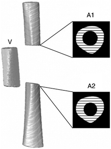
The algorithm next prompted the user to select the slices of the proximal and distal fracture fragments that bordered the fracture gap but contained full cross-sections of bone (). The cross-sectional area of bone (bone-containing voxels) was averaged for the proximal and distal slices and used to determine the longitudinal translation (z) by dividing this area by the total amount of bone in the comminuted volume.
Figure 5. A schematic indicating the cross-sectional areas of bone (black and white hatching) in the gap-bordering slices of the proximal (A1) and distal (A2) fragments. The comminution fragment (V) is also shown to the left of the atlas.
The transformation matrix from the registration of the distal fragment to the atlas was then decomposed into the corresponding Euler angles and translations. The order of decomposition was based on the typical clinical approach and, therefore, was performed as rotations about the x-, y- and, finally, z-axes. This was performed using Equation Set 1, where T is the 4 × 4 3D transformation matrix yielded from the affine registration [Citation20]. Due to the initial alignment of the atlas to the global origin, this corresponded to the α, β and ϕ that were displayed for the user, along with the volume-based leg length correction.
Performance evaluation
The calculated values were compared to the input values from the precision stages. Differences in the two values were calculated for each scan using both atlases, and the error in each of the six alignment measurements was compared between the two atlas models using a two-tailed Student’s paired t test with a significance level of 0.05. The time required for the algorithm to run was also recorded and compared between the two atlas models using a two-tailed Student’s paired t test with a significance level of 0.05. To determine whether the volume of missing bone and the amount of bone visible in the scan effected the accuracy of the algorithm, a Pearson correlation was performed between each of the six alignment measurements and the gap length and minimal amount of bone visible in either the proximal or distal fragment in the scan (the length of the shortest fracture segment). Finally, to determine repeatability, the semi-automated algorithm was run a second time for both atlas models on one scan from each bone (9 scans in total with different gap lengths) and the absolute difference between the first and second measurements was calculated.
Results
The algorithm was able to calculate the relative malalignment within current clinical tolerances in all 6 DOF using both the synthetic and cadaver-based atlas models. summarizes the results from the 9 repeated measurements for each of the 6 DOF. The algorithm was found to be highly repeatable, with an average difference between the initial measurement and the repeated measurement of ≤1.55 mm for all translations and 2° for rotations and angulations. The paired Student’s t test showed no significant difference for the accuracy of the quantification of the A/P and M/L translation, leg length, varus/valgus angulation and periaxial rotation (p > 0.36 for all of these). However, the flexion/extension angulation calculated based on the cadaver-based atlas was found to be more accurate than that calculated based on the synthetic femur, with a mean difference of 1.2° between the two methods (p = 0.043).
Table II. The average difference between the repeated measures for medial/lateral (M/L) translation, anterior/posterior (A/P) translation, leg length, flexion/extension (F/E) angulation, varus/valgus (V/V) angulation and periaxial rotation. The maximum difference between the repeated measurements is also indicated, along with the fracture gap at which the maximum difference occurred.
The average time required for the algorithm to calculate the malalignment was 6:24 min (±50 s, maximum 8:15 min) and 8:42 min (±2:25 min, maximum 13:48 min) for the synthetic-based and cadaver-based atlases, respectively. From the paired Student’s t test, the cadaver-based atlas model required significantly more time to perform the registration and calculate the malalignment, with a mean difference of 2:18 min (p < 0.001). The amount of time required by the user did not differ between the two atlases and was approximately 3 minutes.
The Pearson correlation indicated that the size of the fracture gap had a positive correlation with the error in the calculation of the M/L and A/P translation (r = 0.42, slope = 0.019 and r = 0.66, slope = 0.058, respectively) as well as the calculated errors in flexion/extension angulation (r = 0.55, slope = 0.058) for the synthetic-based atlas and the A/P translation and periaxial rotation (r = 0.68, slope = 0.060 and r = 0.49, slope = 0.042, respectively) for the cadaver-based atlas (all significant at the 0.05 level). No significant correlation was found between the other parameters for either atlas and the size of the fracture gap. The length of the shortest fracture segment was found to have a negative correlation with the error in the calculation of the flexion/extension angulation and periaxial rotation for the synthetic-based atlas (r = −0.56, slope = −0.10 and r = −0.50, slope = −0.069, respectively) at a level of significance of 0.01. No significant correlation was found between the length of the shortest fracture segment and the accuracy of the other parameters in the synthetic-based atlas or the cadaver-based atlas.
Discussion
This study presents a semi-automated algorithm that can calculate the relative alignment of the two main fragments in femoral shaft fractures with comminution in 6 DOF within the current clinical tolerances [Citation6–9, Citation21–23]. Two distinct atlases were investigated for use in the algorithm: a synthetic-based atlas (representing a population average) and a cadaveric-based atlas generated from a single specimen. In both cases, the algorithm was able to quantify the degree of malalignment based on a single CBCT image of the fractured femoral shaft. The algorithm was performed in two main steps: a rigid registration with anisoscaling of the atlas to the proximal fracture fragment, followed by the rigid registration of the distal segment to the atlas, yielding the relative alignment between the two segments.
The accuracy of some of the alignment parameters was affected by the amount of bone that was contained in the comminution volume and the amount of bone that was visible within the scan (the fragment length). This was consistent with our expectation, as both shorter bone fragments and increased comminution length lead to less information being available with which the algorithm can calculate the alignment. However, the size of this effect was small, with a maximum error of 0.06 mm and 0.06° per mm of additional comminution and 0.10° per mm of the minimum visible fragment length. Also, the accuracy of the majority of parameters was found to have no significant correlation to the size of the fracture gap or minimum fragment length. For fracture gaps of up to 76 mm, and with a minimum visible fragment length of 42 mm, the algorithm was able to quantify successfully malalignment of the fracture in 6 DOF to current clinical standards.
The cadaveric-based atlas yielded slightly more accurate results (1.2°) in the calculation of the flexion/extension angulation, with no significant differences being found between the two atlases in the other 5 DOF. The cadaveric-based atlas required significantly more time to perform the registration and alignment quantification, probably due to the presence of more varied features along its surface. As the synthetic-based atlas represents a population average, some of the surface features, such as the linea aspera, are less defined and there are no irregular surface features. Additionally, the synthetic-based atlas has a more uniform density, yielding more uniform segmentation and a smoother surface. Future work may investigate the development of an optimized atlas incorporating features of the synthetic and cadaveric femora to provide improved accuracy and computational speed.
This algorithm was not fully automated in that it requires initial manual alignment of the atlas to the proximal fragment and of the distal fragment to the atlas. The manual input is simple and rapid, requiring approximately 3 minutes in total. The robust and repeatable results from the algorithm are encouraging when considering its potential for translation to the clinical setting. Current navigation systems require acquisition of multiple fluoroscopic images on both the fractured and intact limb and the selection of anatomical landmarks, from which the quantification of leg length and periaxial rotation are calculated. Although time requirements for the use of fluoroscopy-based navigation have not been widely documented, Kendoff et al. reported times from 16–18 min [Citation13]. Other navigated methods have been reported to increase overall procedural time, despite a reduction in radiation exposure time, due to the image acquisition and registration process, as well as the additional set-up and equipment required. The present algorithm could be incorporated into current tracking systems using a single CBCT scan of the fractured limb (with mounted distal and proximal trackers).
The presented algorithm also provides quantification of the fracture in 6 DOF, which is not present in some of the current navigation techniques which solely provide quantification of the leg length and periaxial malrotation, and rely on surgeon judgment for the additional translational and rotational alignments [Citation14, Citation24, Citation25]. Additionally, the single intraoperative CBCT scan could reduce radiation exposure for surgical staff (who could be shielded during image acquisition) with no additional fluoroscopic imaging being needed for reduction.
Current fluoroscopy-based navigation techniques have several inherent limitations. Many require images of an intact contralateral limb (which is not always available). Additionally, the metrics used to evaluate the current methods are 2D-based and, therefore, may have systemic errors leading to the varied reports of accuracy, particularly in the determination of periaxial rotation. Hofstetter et al. [Citation14], in one of the initial reports on using fluoroscopic landmark identification for the determination of periaxial rotation, found an average accuracy of 3.6° with a maximum of 9° difference in unfractured pairs of femora. Weil et al. [Citation26] reported average accuracies of 1.9 mm for leg length calculations and 2.5°, using a pre-osteotomy scan of the same femur for a fracture gap of 50 mm. However, these results were based on a single femur and, instead of using the contralateral limb for length and periaxial rotation determination, images of the same femur from before the fracture was simulated were used during the matching scheme. In a series of three patients, Kendoff et al. [Citation13] measured anteversion postoperatively using CT scans and found, in three cases, that the periaxial rotation was restored to within 4° of that of the healthy side. Due to the reliance on the presence of an intact contralateral limb, such fluoroscopic methods could not be used to determine periaxial rotation or leg length in patients with bilateral fractures. Furthermore, no information was provided on the level of comminution in the three treated fractures, making evaluation of the alignment difficult to assess. Keast-Butler et al. [Citation25] observed no significant difference between the reduction accuracy achieved with fluoroscopy-based navigation and conventional fluoroscopy (maximum error was 20° for both groups). Citak et al. [Citation15] found that, when using non-orthogonal images, with an angle of less than 50° between the two images, the periaxial rotation was measured to be from 2.3 to 7.7° different from that calculated from a CT-based measurement of anteversion of the same femur. Therefore, off-angle fluoroscopic images can further decrease the calculation of the periaxial rotation.
Previous computer assisted methods based on CT and fluoroscopic guidance have mainly focused on determination of periaxial rotation [Citation13, Citation15, Citation26–32]. The FRACAS system developed by Joskowicz et al. [Citation30] is CT-based and enables 3D visualization of the fracture fragments, but requires preoperative CT imaging of the fractured and contralateral healthy limb and their registration to fluoroscopic images. In pilot studies [Citation31], landmarks placed on the posterior femoral condyles and the neck axis of the healthy and fractured side were able to guide the fracture to within 1.0 to 4.5° of the alignment of the healthy limb, based on the measurement of the selected landmarks. However, this method requires substantial radiation exposure through preoperative CT and intraoperative fluoroscopy.
Three-dimensional CT-based surface information has been used, by our group and others, to determine periaxial rotation of fractured femurs with accuracies from 1.6 to 3° [Citation33, Citation34]. Each group used a surface-matching approach and resampled the femoral shaft about its center to yield surface maps of the femur. Additionally, Moghari and Abolmaesumi [Citation35] obtained promising results using a statistical atlas for the registration of bone fragments in femoral neck fractures, reporting registration errors of approximately 1.6 mm. These approaches are advantageous as they require no information from the contralateral limb. A surface matching approach could ultimately be incorporated into the atlas-based approach to provide fine tuning of the periaxial rotation.
More recent work has integrated surface matching with a principal axis-based approach to allow the determination of malalignment of fractured femora in 6 DOF [Citation36]. This work demonstrated robust performance that can be directly compared to the current algorithm (the principal axis/surface-based approach was applied to the same data set of CBCT images). The principal axis/surface-based approach achieved clinical tolerances in all but two cases (one case at the extreme of comminution length and one case with the minimum length of fracture fragment), while the present work achieved clinical tolerances in all 27 fracture cases. A paired Student’s t test showed no significant difference between the principal axis/surface-approach and the atlas-based method in the present work for all alignment parameters (p ≥ 0.20) but periaxial rotation (p < 0.001; both atlases achieved greater accuracy) and the flexion/extension angulation (p = 0.02; the cadaveric-based atlas achieved greater accuracy). However, the principal axis/surface method was more rapid (average time for analysis of 5 min 58 s) than the atlas-based method presented here (average analysis times of 6 min 24 s and 8 min 42 s for the synthetic and cadaver-based atlases, respectively).
Intensity-based threshold segmentation of cortical bone is robust even in the presence of soft tissue, particularly at the high resolution and image quality that can be achieved with CBCT. As such, the lack of soft tissue in the CBCT images in this study would likely have little effect on the segmentation or algorithm performance. Additionally, the algorithm currently requires the input of separate image stacks for the proximal, distal and comminution bone volumes. The high quality and contrast in the CBCT images, the femoral shaft geometry and the absence of trabecular bone make the intensity-based segmentation and cropping of the relevant bony volumes straightforward and repeatable.
The algorithm in this study was not tested to its limits for fracture gap, minimal length of bone or fracture malalignment. However, alignments in excess of those that were created using the precision stages in this study would be less relevant to clinical practice, as they would be readily apparent on 2D images and may be partially reduced by the placement of a patient in traction prior to surgery. The fracture gap of 76 mm represents substantial bone loss. Fracture gaps in excess of this length would likely start to approach the epiphyses and, additionally, would limit the amount of bone visible within the field of view. Future analyses will determine the minimum fracture fragment length necessary for accurate registration and alignment.
Overall, this algorithm enables repeatable and robust quantification of malalignment of femoral shaft fractures in 6 DOF within clinical tolerances based on a single initial intraoperative CBCT image of the fractured limb. The incorporation of this algorithm with a navigation system that can support intraoperative CBCT images presents a promising alternative to the current fluoroscopy-based navigation. Integration and validation of 3D algorithms in intraoperative CBCT imaging/navigation systems and their associated workflow will ultimately demonstrate their translational potential.
Declaration of interest
The authors report no declarations of interest.
Acknowledgements
The authors would like to acknowledge the work of Dr. Ernest Lam and the Department of Radiology of the Faculty of Dentistry, University of Toronto, for their expertise and assistance in image acquisition.
References
- Arneson TJ, Melton LJ 3rd, Lewallen DG, O’Fallon WM. 1988. Epidemiology of diaphyseal and distal femoral fractures in Rochester, Minnesota, 1965–1984. Clin Orthop Relat Res 234:188–94
- Ricci WM, Gallagher B, Haidukewych GJ. 2009. Intramedullary nailing of femoral shaft fractures: current concepts. J Am Acad Orthop Surg 17:296–305
- Jaarsma RL, Pakvis DF, Verdonschot N, et al. 2004. Rotational malalignment after intramedullary nailing of femoral fractures. J Orthop Trauma 18:403–9
- Braten M, Terjesen T, Rossvoll I. 1993. Torsional deformity after intramedullary nailing of femoral shaft fractures. Measurement of anteversion angles in 110 patients. J Bone Joint Surg Br 75:799–803
- Harris I, Hatfield A, Walton J. 2005. Assessing leg length discrepancy after femoral fracture: clinical examination or computed tomography? ANZ J Surg 75:319–21
- Rush WA, Steiner HA. 1946. A study of lower extremity length inequality. Am J Roentgenol Radium Ther 56:616–23
- Thoresen BO, Alho A, Ekeland A, et al. 1985. Interlocking intramedullary nailing in femoral shaft fractures. A report of forty-eight cases. J Bone Joint Surg Am 67:1313–20
- Webb LX, Gristina AG, Fowler HL. 1988. Unstable femoral shaft fractures: a comparison of interlocking nailing versus traction and casting methods. J Orthop Trauma 2:10–12
- Wiss DA, Brien WW, Stetson WB. 1990. Interlocked nailing for treatment of segmental fractures of the femur. J Bone Joint Surg Am 72:724–8
- Winquist RA, Hansen ST Jr, Clawson DK. 1984. Closed intramedullary nailing of femoral fractures. A report of five hundred and twenty cases. J Bone Joint Surg Am 66:529–39
- Ricci WM, Bellabarba C, Evanoff B, et al. 2001. Retrograde versus antegrade nailing of femoral shaft fractures. J Orthop Trauma 15:161–9
- Wolf H, Schauwecker F, Tittel K. 1984. Malrotation following intramedullary nailing of the femur. Unfallchirurgie 10:133–6
- Kendoff D, Citak M, Gardner MJ, et al. 2007. Navigated femoral nailing using noninvasive registration of the contralateral intact femur to restore anteversion. Technique and clinical use. J Orthop Trauma 21:725–30
- Hofstetter R, Slomczykowski M, Krettek C, et al. 2000. Computer-assisted fluoroscopy-based reduction of femoral fractures and antetorsion correction. Comput Aided Surg 5:311–25
- Citak M, Kendoff D, Pearle AD, et al. 2009. Navigated femoral anteversion measurements: general precision and registration options. Arch Orthop Trauma Surg 129:671–7
- Siewerdsen JH, Jaffray DA, Edmundson GK, et al. 2001. Flatpanel cone-beam CT: A novel imaging technology for image-guided procedures. Proc SPIE 4319:435–44
- Ibanez L, Schroeder W, Ng L, Cates J. 2005. The ITK Software Guide 2005
- Maes F, Collignon A, Vandermeulen D, et al. 1997. Multimodality image registration by maximization of mutual information. IEEE Trans Med Imaging 16:187–98
- Thevenaz P, Unser M. 2000. Optimization of mutual information for multiresolution image registration. IEEE Trans Image Process 9:2083–99
- Ginsberg JH. 1995. Advanced Engineering Dynamics, 2nd ed. New York: Cambridge University Press
- Giles LG, Taylor JR. 1981. Low-back pain associated with leg length inequality. Spine (Phila Pa 1976) 6:510–21
- Moed BR, Watson JT, Cramer KE, et al. 1998. Unreamed retrograde intramedullary nailing of fractures of the femoral shaft. J Orthop Trauma 12:334–42
- Ricci WM, Bellabarba C, Lewis R, et al. 2001. Angular malalignment after intramedullary nailing of femoral shaft fractures. J Orthop Trauma 15:90–5
- Mosheiff R, Weil Y, Peleg E, Liebergall M. 2005. Computerised navigation for closed reduction during femoral intramedullary nailing. Injury 36:866–70
- Keast-Butler O, Lutz MJ, Angelini M, et al. 2012. Computer navigation in the reduction and fixation of femoral shaft fractures: a randomized control study. Injury 43:749–56
- Weil YA, Gardner MJ, Helfet DL, Pearle AD. 2007. Computer navigation allows for accurate reduction of femoral fractures. Clin Orthop Relat Res 460:185–91
- Matthews F, Hoigne DJ, Weiser M, et al. 2007. Navigating the fluoroscope’s C-arm back into position: an accurate and practicable solution to cut radiation and optimize intraoperative workflow. J Orthop Trauma 21:687–92
- Gösling T, Oszwald M, Kendoff D, et al. 2009. Computer-assisted antetorsion control prevents malrotation in femoral nailing: an experimental study and preliminary clinical case series. Arch Orthop Trauma Surg 129:1521–6
- Mosheiff R, Weil Y, Peleg E, Liebergall M. 2005. Computerised navigation for closed reduction during femoral intramedullary nailing. Injury 36:866–70
- Joskowicz L, Milgrom C, Simkin A, et al. 1998. FRACAS: a system for computer-aided image-guided long bone fracture surgery. Comput Aided Surg 3:271–88
- Ron O, Joskowicz L, Milgrom C, Simkin A. 2002. Computer-based periaxial rotation measurement for aligning fractured femur fragments from CT: a feasibility study. Comput Aided Surg 7:332–41
- Hazan EJ, Joskowicz L. 2003. Computer-assisted image-guided intramedullary nailing of femoral shaft fractures. Techniques in Orthopaedics 18:191–200
- Khoury A, Whyne CM, Daly M, et al. 2007. Intraoperative cone-beam CT for correction of periaxial malrotation of the femoral shaft: a surface-matching approach. Med Phys 34:1380–7
- Tsao J, Chiodo CP, Williamson DS, et al. 1998. Computer-assisted quantification of periaxial bone rotation from X-ray CT. J Comput Assist Tomogr 22:615–20
- Moghari MH, Abolmaesumi P. 2008. Global registration of multiple bone fragments using statistical atlas models: feasibility experiments. Conf Proc IEEE Eng Med Biol Soc 2008:5374–7
- Crookshank M, Beek M, Singh D, et al. 2013. Can a semi-automated surface matching and principal axis-based algorithm accurately quantify femoral shaft fracture alignment in six degrees of freedom? Med Eng Phys 35(7):1028–36