
Abstract
Resection of a pelvic tumor is challenging because of its complex three-dimensional (3D) anatomy and deep-seated location with nearby vital structures. The resection is technically demanding if a custom implant is used for reconstruction of the bone defect as the surgeon needs to ensure the resection margin is sufficiently wide and the orientation of intended resection planes must match that of the custom implant. We describe a novel workflow of performing a partial acetabular resection in a patient with pelvic chondrosarcoma and reconstruction with a custom pelvic implant in a one-step operation. A multi-planar bone resection was virtually planned. A computer-aided design implant that both matched the bone defect and biomechanically evaluated was prefabricated with 3D printing technology. The 3D-printed patient-specific instruments (PSIs) were used to reproduce the same planned resection. The histology of the tumor specimen showed a clear resection margin. The errors of the achieved resection and implant position were deviating (1–4 mm) from the planned. The patient could walk unaided with a good hip function. No tumor recurrence and implant loosening were noted at 11 months after surgery. The use of this novel CT-based method for surgical planning, the engineering software for implant design and validation, together with 3D printing technology for implant and PSI fabrication makes it possible to generate a personalized, biomechanically evaluated implant for accurate reconstruction after a pelvic tumor resection in a one-step operation. Further study in a larger population is needed to assess the clinical efficacy of the workflow in complex bone tumor surgery.
Introduction
Custom pelvic prostheses were used to reconstruct the bone defect following complex pelvic bone tumor resection.[Citation1–3] The method allows the engineer to design and tailor-made an implant that matches exactly to the anticipated bone loss after tumor resection. However, the degree of fitting of the custom implant depends greatly on the ability of the surgeons to reproduce the resection as planned. Bone tumor resection and reconstruction with a prefabricated custom implant has been advocated with the use of computer-assisted approach.[Citation4–7] The exact level and orientation of planned bone resection can be executed under navigation guidance at the time of surgery. The pre-fabricated custom implant can then be implanted and matched accurately to the anticipated bone defect after resection in one stage.
Computer navigation has been used with the aim of achieving increased accuracy and precision in orthopedic surgery. Patient-specific instrument (PSI) has been reported as an alternative intraoperative assistance to computer navigation. PSI is applied to joint arthroplasty,[Citation8,Citation9] spinal pedicle screws insertion [Citation10,Citation11] and deformity correction.[Citation12,Citation13]
PSI has recently been investigated in bone tumor surgery. Pelvic tumor resection under the PSI guidance was simulated in a sawbone study. It could provide good bone cutting accuracy and might improve pelvic tumor surgery by achieving clinically acceptable margins.[Citation14] PSI has been described in a case report that it could facilitate the resection of extremity bone tumor and reconstruction with a custom prosthesis, similar to that achieved by navigational assistance.[Citation15]
As pelvic bone has complex three dimensional (3D) geometry, 3D printing technology with Additive Layer Manufacturing (ALM) techniques will be ideal for fabricating an anatomical conforming custom implant with internal lattice structures that enhance osseointegration at the bone–implant junctions. This technology has recently been reported in revision total hip arthroplasty with severe acetabular bone loss and pelvic discontinuity.[Citation16] Patient-specific custom acetabular components that match precisely the acetabular bone defect were designed and then 3D printed for a one stage operation.
In this paper, we describe a novel workflow of performing a partial acetabular resection in a patient with pelvic chondrosarcoma and reconstruction with a custom pelvic implant. A multiplanar bone resection was virtually planned. A computer-aided design (CAD) implant that matched the bone defect and which was biomechanically evaluated, was prefabricated with 3D printing technology. The PSI was then used to reproduce the same planned resection to fit the custom CAD implant. The accuracy of the workflow was validated by comparing the achieved resection and implant position with the planned.
Case report
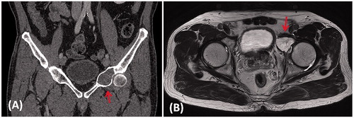
A 65-year-old man presented with left hip pain for one year. MR imaging of the pelvis showed an expansile osteolytic destruction at the anterior column of left acetabulum (). CT-guided biopsy revealed low grade chondrosarcoma. Staging investigations showed localized disease. Pelvic tumor resection and prosthetic reconstruction of the bone defect were planned.
Figure 1. (A) A coronal CT image and (B) an axial T2-weighted MR image in a patient with a low grade chondrosarcoma involving the anterior column of left acetabulum (red arrows).
Axial CT images of the pelvis were acquired just prior to CT guided biopsy using a 16-detector scanner (LightSpeed VCT XT, GE Healthcare, Milwaukee, WI). Slices of 0.0625 mm thickness were obtained with a soft tissue algorithm. The CT images in DICOM format were then imported into medical image analysis software (MIMICS 15.0, Materialise NV, Leuven, Belgium).
Preoperative planning
Virtual surgical simulation
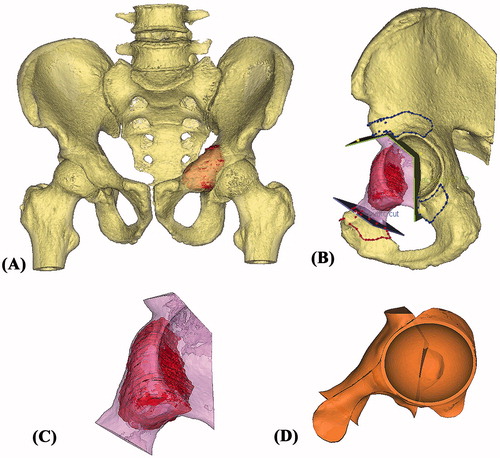
The CT image data sets were then reformatted into coronal and sagittal views in addition to the original axial views. A gray-valued based segmentation of the CT images excluded the soft tissue and a 3D model of the affected hemi-pelvis was generated for surgical simulation. As MR images showed the same intraosseous tumor involvement as on the CT images, the extent of the tumor was outlined from the CT images and its volume was extracted. A 3D bone-tumor model was then created (). All the reformatted 2D images and 3D models were analyzed for preoperative surgical planning. A partial acetabular resection with a 10-mm safe margin was virtually simulated (). The working file of the surgical simulation was then forwarded to the implant engineer (Mobelife NV, Leuven, Belgium).
Figure 2. (A) The 3D pelvis was segmented by the thresholding process in the CAD software. The extent of tumor was outlined on each axial CT image and its tumor volume was extracted (red in color). A 3D bone tumor model was created for the surgical planning. (B) Surgeons performed the virtual resections by defining the locations and orientations of the resection planes. The planes were 1 mm in thickness, the same as that of the oscillating saw used during the actual surgery. The footprints at where the PSI was positioned were marked on the bone surface (red and blue lines). The working file of the surgical plan was then sent to the implant engineer for the design of the implant and PSI. (C) The virtually resected tumor was extracted. As the bone was deformed by the tumor, the mirrored 3D image from the normal side of the hemipelvis was used to duplicate the core shape of the implant. (D) The flanges and the acetabular cup were added for better implant stability. The final implant design had a normal acetabular contour and the components for implant fixation.
Design of the Patient-specific pelvic implant
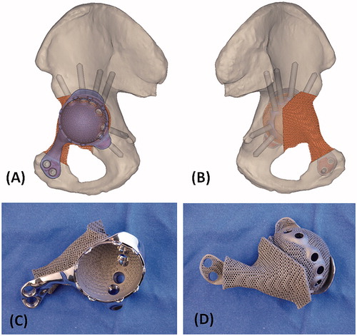
The shape of the bone defect after virtual resection was re-created by overlapping the mirror image at the corresponding region of the unaffected opposite pelvis (). The implant shape was designed with the consideration of surgical approach and surrounding soft tissues. The bone defect was filled with a porous scaffold which was rigidly connected to a solid plate (). As the resected bone ends did not have adequate bone contact for implant fixation, it was decided to resurface the remaining acetabulum that also provided good bone for stable fixation. Acetabular cup orientation was anatomically analyzed for inclination and anteversion. The surgical window and surrounding soft tissue were also taken into account to determine the shape of the implant. A cemented acetabular liner with 48 mm outer diameter and 32 mm inner diameter (Trident all poly, Stryker, Mahwah, USA) was chosen for fixation. Screw positions and lengths were also planned, based on the bone thickness and quality of the remaining bone after resection ().
Figure 3. The 3D pelvic model (A: lateral view; B: medial view) showed the implant reconstruction and screws fixation. Screw positions and lengths were planned, based on the bone thickness and quality of the remaining bone after resection. The implant design and the reconstruction were then subjected to FEA evaluation. After the surgeons approved the implant design, the implant was 3D printed as a titanium monoblock. (C) The outer view of the implant showed the solid plate, flanges and the acetabular cup with screws holes for fixation. (D) The back side of the implant showed the porous scaffold that was in contact to the host bone. The scaffold has an interconnected network of pores with an average porosity of 70%. The pores have an average size of 720°μm and the thickness of the solid struts is around 350°μm. This allows the bone to grow inside the construct to achieve a stable biological fixation. The porous construct is also highly resistant to mechanical compression, while its elastic modulus is comparable to that of bone to minimize the risk of the peri-implant stress shielding.
The patient-specific, biomechanical evaluated pelvic implant
The implant design was biomechanically evaluated with an individualized finite element analysis by dedicated engineering software (Abaqus, Dassault Systèmes, Vélizy-Villacoublay, France) prior to the actual implant manufacture. A finite element model (FEM) was built that contained 3D representations of the implant and the affected hemi-pelvic bone after tumor resection (). The model was made patient-specific, based on: (i) the geometries of the bone and implant; (ii) the material properties of the bone; (iii) and the loading condition with regards to the patient’s height and weight. By simulating the FEM to a loading condition that corresponded to the maximal loads exerted on the hip joint during gait, we calculated and analyzed the mechanical response of the implant and bone. The stresses in the implant were assessed to ensure the implant integrity. In addition, stress values and strain distribution in the bone were investigated. High stress peaks in the bone were avoided to minimize the risk of bone fractures. Strain distribution in the bone was monitored to check that no regions were shielded from the loads. After the patient-specific FEA evaluation, the implant design was found to have adequate implant strength. The bone loading did not exceed the safe range, causing neither bone fracture nor stress shielding ().
Figure 4. The 3D models of the hemipelvic bone and the implant were further processed to obtain a 3D tetrahedral mesh (3Matic, Materialise NV, Leuven, Belgium) suitable for FEA. A FEM was generated. (A) The lateral view and (B) the medial view of the pelvis with implant reconstruction. The material properties of the implant were assigned to the titanium alloy it is made of. Individualized material properties were assigned to the cortical region and density dependent properties to the trabecular regions of the hemipelvic bone. Starting from the patient’s height and weight, individualized muscle and joint forces were obtained using musculoskeletal modeling. The forces in the muscles (yellow arrows) were applied on the specific regions on the hemi-pelvis that corresponded to the muscles’ attachment regions. The joint force was applied in the newly reconstructed joint surface of the implant. Finally, boundary conditions were defined that fixed the hemi-pelvis at the sacro-iliac joint and pubis symphysis (orange arrows). The FEM simulated the maximal loads that occur on the hip joint during gait motion and the mechanical response of the implant and bone was calculated. (C) The stress distribution showed the design had adequate implant integrity. The bone loading did not cause any bone fracture nor stress shielding. (D) The implant with the block design reconstructing only the bone defect without the additional acetabular cup component was also FEA evaluated after surgery. The result showed a critically high stress pattern in the implant with block design than that of the implant with cup design. It supported the surgeon’s choice of resurfacing the hip joint at the posterior column of the remaining acetabulum.

After the surgeons approved the design, the final implant that consisted of the scaffold, plate and acetabular cup was 3D printed as a titanium monoblock (). The implant was fabricated with ALM techniques, using selective laser melting techniques in medical grade Ti6Al4V material. The parts were cleaned ultrasonically. Sterilization was performed in the hospital.
Tumor PSI and bone models during the surgery
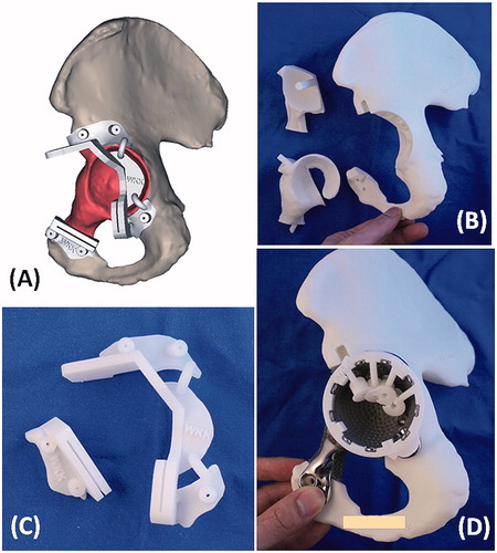
The resection planning was transferred into the surgery by using PSI technology (). The cutting platforms and slits of the PSI had the unique orientation of the resection planes defined by surgeons during virtual simulation. Surgeons also marked on the bone surface of the virtual 3D images that could be accessed at the surgical approach and chosen as the footprints for PSI positioning. The contoured flanges of the PSI were then designed with reference to the marked footprints in such a way that the PSI could be positioned consistently at the planned resection without translation. It helped reproduce accurately the planned multiplanar osteotomy at the acetabulum and the uniplanar osteotomy at superior pubic ramus. A custom drill guide, fitting on the implant, was made to predrill the trajectories of the planned screws after implant insertion. In addition to the tumor PSI and drill guide, the affected hemipelvis and the trial of the implant were also 3D printed with the selective laser sintering technique using medical grade polyamide. The printed 3D models provided surgeons a hand-on surgical rehearsal of the PSI-guided resection and reconstruction prior to the real surgery ().
Figure 5. (A) The design of PSI had the cutting platforms or slits that matched the planned resection planes; the flanges with the contoured shape that allowed a unique PSI positioning on the surgical accessible bone surface decided by the surgeons at the CAD software; and the K-wire holes on the flanges for stabilizing the PSI to the bone. (B) The 3D-printed models included the implant trial, the resected bone tumor together with the removed acetabular bone and the remaining pelvic bone after tumor resection. These models allowed surgeon to rehearse the procedures prior to the real surgery. (C) The 3D-printed tumor PSI. (D) The drill guide on the implant for drilling the screw paths.
It took about 2 months from the start of the design process and the final delivery of the implant and models to the surgeon.
Intraoperative execution
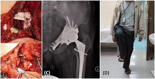
The patient was placed in a semi-lateral position. An ilioinguinal approach with femoral extension was used. Femoral and obturator neurovascular bundles were identified and protected. Iliopsoas tendon and abductor muscle were preserved. After the femoral neck was osteotomized, the femoral head was removed to expose the acetabular cavity. The bone surface near the planned resection sites was exposed. The flanges of the tumor PSI were firmly seated on the bone surface and then stabilized with 1.6 mm Kirschner wires (). It took about 3 min to set the locations of the tumor PSI. Two minutes were spent to make the guided bone resections via the cutting platforms and slits of the PSI. The partial acetabular resection was completed and the tumor was removed en-bloc. The remaining acetabular surface was reamed. The patient-specific CAD implant was adapted well to the bone defect and then fixed with titanium trabecular screws after drilling via the custom drill guide (). The polyethylene liner was cemented to the acetabular cup of the pelvic implant. A cementless stem and a 32-mm metal head were inserted into the femur side in a standard manner. A small crack of the femoral neck was developed after insertion of the femur stem. It was protected with a cerclage wire.
Figure 6. (A) The femoral neurovascular bundles and iliopsoas muscle were protected and retracted medially. The PSI for the acetabular and pubic osteotomies was positioned and secured with K-wires. (B) After PSI-guided tumor resection, the implant was fitted precisely to the bone defect and stabilized with multiple screws fixation as planned. At 10 months after the surgery, the anteroposterior radiograph of the pelvis (C) showed good implant alignment and no evidence of implant loosening. (D) The patient could walk unaided and could achieve single leg standing.
Postoperative validation
The postoperative course was uneventful. No neurovascular complications or wound infection was noted. The patient was allowed to walk with protected weight bearing in a hip brace two weeks after the surgery. He walked with full weight bearing 4 weeks after surgery. The brace was discarded at 8 weeks after he had gained good hip control. By 10 months, he experienced no hip pain and could walk independently without aids (). There was no evidence of tumor recurrence. The plain radiograph of the pelvis showed satisfactory implant alignment and no evidence of implant loosening ().
The histology of the tumor specimen showed a clear resection margin. CT scan of the resected tumor was performed and the CT images were merged with the preoperative planning. The errors of the achieved resections were deviating (1.3–4.0 mm) from the planned resections (). The achieved position of the CAD implant was also comparable with the planned when merging the postoperative CT images of the pelvis with the preoperative planning ( and ).
Figure 7. (A) The CT images of the resected tumor specimen (blue in color) were compared with that of the surgical planning (yellow and red in color). The errors of the achieved resections were ranged from 1.3 to 4.0 mm. (B and C) The achieved implant position (blue in color) was comparable with the planned (purple in color). The deviations of achieved cup orientation and position are summarized in .
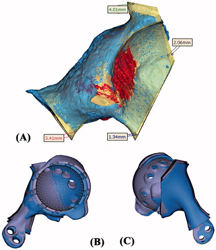
Table 1. The comparison between the achieved implant position and the planned.
Discussion
Resection of a pelvic tumor is challenging because of its complex 3D anatomy and deep-seated location with nearby vital structures. Achieving a tumor-free margin is the most important factor that surgeons can control for the better oncological outcomes in patients with pelvic tumors.[Citation17–19] The resection is technically demanding if a custom implant is used for reconstruction of the bone defect as the surgeon needs to ensure the resection margin is sufficiently wide and the orientation of the intended resection planes must match that of the custom implant. Computer navigation has been successfully used to facilitate this accurate tumor resection and reconstruction with correct implant positioning in a one-step operation.[Citation6,Citation7]
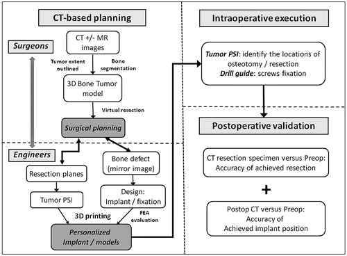
In this study, we described the workflow of 3D planning and one-step operation for a pelvic tumor resection and reconstruction with a 3D printed custom implant (). The comparable resections between the planned and the achieved supported the use of the tumor PSI to reproduce the virtual surgical planning. It concurred with the results in a simulated sawbone study that the 3D planning and PSI could improve the accuracy of pelvic bone tumor surgery.[Citation14] Our finding suggested that the tumor PSI might even support a more difficult multiplanar osteotomy in the pelvic region with complex anatomy. This enabled surgeons to resect bone tumors with just adequate margin but yet it could maximally preserve the surrounding normal bone for reconstruction with a better function. In contrast to computer navigation assisted surgery, the tumor PSI could achieve an acceptable resection accuracy by a shorter time and did not involve bulky instruments and other supporting facilities.[Citation14,Citation15] Also, the favorable final implant position suggested that the tumor PSI not only facilitated a resection with a tumor-free margin, but also a correct orientation of the planned resection to precisely fit the custom implant with a complex geometry.
By the oncological principle, tumor clearance only required partial acetabular resection without the need of resurfacing the remaining acetabulum in this patient. FEA was performed postoperatively to evaluate the mechanical performance of the block implant if the cup component was not added to the design. The result of the FEA showed that Von Mises stresses in block implant and bone were higher than that in the cup implant (). The strain distribution and deformation of the cup implant design suggested a stiffer implant, leading to less deformation and stresses at the cup portion. It supported the surgeons’ initial choice that the cup implant was a better design than the block implant for the patient. Therefore, the design of custom tumor implant not only had the structural geometry that matched the bone defect after resection, but also fulfilled the biomechanical requirements under the patient-specific loading conditions. A biomechanical in vitro testing has been reported to evaluate the stability of different reconstruction in pelvic tumor surgery.[Citation20] However, the method could not include the effect of muscle and bone for analysis in a particular individual and also it could not be performed preoperatively for the custom implant reconstruction. FEA has been used to evaluate and compare the proposed custom design of a custom femoral component with a conventional design in total knee replacement.[Citation21] The paper showed that the custom design had a more even stress distribution on the bone–implant interface, which would reduce an uneven bone remodeling that would result in premature loosening. We found that the virtual testing by FEA could be applied to the design of custom bone tumor implant. It might optimize the design prior to the actual fabrication and assist surgeons in providing the best personalized implant for an individual bone tumor patient. Increase in lead time to implementation spending on the preoperative virtual simulation can be a concern in tumor surgery as tumor may grow in size during the planning period. Therefore, the proposed technique may be restricted to the slow growing bone tumors such as low grade bone sarcoma described in this report. Also, the virtual FEA simulation is performed under hypothetical loading conditions and it may not fully represent the real biomechanical environment of the patient. It is anticipated that with advances in technology, the preoperative virtual testing will be performed faster and the results are reflecting close to the real postoperative situations.
Figure 8. The workflow of using CT-based 3D surgical planning, biomechanically evaluated implant and PSI guided resection and reconstruction in a one-step bone tumor surgery. The workflow requires close collaboration between surgeons and engineers in order to achieve the personalized surgery with sound oncological and biomechanical principles. FEA, finite element analysis; PSI, patient-specific instrument.
3D printing with ALM technique uses a high-powered laser to selectively melt fine metal powder in thin layers and then builds up the geometry by adding metal materials layer by layer. It can then generate the complex free-form structure such as scaffold lattice in a metal monoblock that would be impossible using conventional subtractive manufacturing techniques by computer numerical control machines. The ALM technique has been successfully used in the craniofacial reconstruction, dental applications and customized hip implants,[Citation22–25] but is not reported in orthopedic bone tumor surgery. The early results of using 3D printed titanium trabecular lattice structure to fill up and reconstruct extensive acetabular bone defect were promising in the revision hip arthroplasty.[Citation16] We found the technique was also useful in the reconstruction of the complex 3D pelvic bone defect after tumor resection. The implant conformed to both the normal bony anatomy and the geometry of the planned bone defect. It contained 3D integral lattice structures that not only reduced the implant weight, but also was in direct contact to the host bone at the resection sites to promote bone in growth. It thus provided the best chances for the long-term implant stability and survival. It may open up a potential area for the development in patient-specific orthopedic tumor implants. However, more studies are required, including the most optimal design with regards to the biomechanical compatibility and manufacturing requirements for the tumors implants with different geometries at different anatomical sites; the best implant surface that is optimal for both osseointegration and mechanical properties at the bone–implant junctions.
In conclusion, the use of this novel CT-based method for surgical planning, engineering software for implant design and validation, together with 3D printing ALM technology for implant and PSI fabrication makes it possible to generate a patient-specific, biomechanical evaluated implant that can be fitted precisely to patient after tumor resection in a one-step operation. The routine process of the proposed workflow needs to be streamlined and the collaboration between the surgeons and biomedical engineers to be further developed, so to make the working platform more efficient and user-friendly in orthopedic bone tumor surgery.
Declaration of interest
The authors (K. C. Wong and S. M. Kumta) report no declaration of interests. N. Van Geel, J. Demol are biomedical engineers working in Mobelife NV, Belgium. The Materialise and Mobelife companies have not funded or sponsored this research in any way.
References
- Dai KR, Yan MN, Zhu ZA, Sun YH. Computer-aided custom-made hemipelvic prosthesis used in extensive pelvic lesions. J Arthroplasty 2007;22:981–986.
- Jaiswal PK, Aston WJ, Grimer RJ, et al. Peri-acetabular resection and endoprosthetic reconstruction for tumours of the acetabulum. J Bone Joint Surg Br 2008;90:1222–1227.
- Sun W, Li J, Li Q, et al. Clinical effectiveness of hemipelvic reconstruction using computer-aided custom-made prostheses after resection of malignant pelvic tumors. J Arthroplasty 2011;26:1508–1513.
- Wong KC, Kumta SM, Chiu KH, et al. Precision tumour resection and reconstruction using image-guided computer navigation. J Bone Joint Surg Br 2007;89:943–947.
- So TY, Lam YL, Mak KL. Computer-assisted navigation in bone tumor surgery: seamless workflow model and evolution of technique. Clin Orthop Relat Res 2010;468:2985–2991.
- Wong KC, Kumta SM. Computer-assisted tumor surgery in malignant bone tumors. Clin Orthop Relat Res 2013;471:750–761.
- Wong KC, Kumta SM. Joint-preserving tumor resection and reconstruction using image-guided computer navigation. Clin Orthop Relat Res 2013;471:762–773.
- Ng VY, DeClaire JH, Berend KR, et al. Improved accuracy of alignment with patient-specific positioning guides compared with manual instrumentation in TKA. Clin Orthop Relat Res 2012;470:99–107.
- Nunley RM, Ellison BS, Zhu J, et al. Do patient-specific guides improve coronal alignment in total knee arthroplasty? Clin Orthop Relat Res 2012;470:895–902.
- Ryken TC, Owen BD, Christensen GE, Reinhardt JM. Image-based drill templates for cervical pedicle screw placement. J Neurosurg Spine 2009;10:21–26.
- Merc M, Drstvensek I, Vogrin M, et al. A multi-level rapid prototyping drill guide template reduces the perforation risk of pedicle screw placement in the lumbar and sacral spine. Arch Orthop Trauma Surg 2013;133:893–899.
- Takeyasu Y, Oka K, Miyake J, et al. Preoperative, computer simulation-based, three-dimensional corrective osteotomy for cubitus varus deformity with use of a custom-designed surgical device. J Bone Joint Surg Am 2013;95:e173.
- Miyake J, Murase T, Moritomo H, et al. Distal radius osteotomy with volar locking plates based on computer simulation. Clin Orthop Relat Res 2011;469:1766–1773.
- Cartiaux O, Paul L, Francq BG, et al. Improved accuracy with 3D planning and patient-specific instruments during simulated pelvic bone tumor surgery. Ann Biomed Eng 2014;42:205–213.
- Wong KC, Kumta SM, Sze KY, Wong CM. Use of a patient-specific CAD/CAM surgical jig in extremity bone tumor resection and custom prosthetic reconstruction. Comput Aided Surg 2012;17:284–293.
- Colen S, Harake R, De Haan J, Mulier M. A modified custom-made triflanged acetabular reconstruction ring (MCTARR) for revision hip arthroplasty with severe acetabular defects. Acta Orthop Belg 2013;79:71–75.
- Ozaki T, Flege S, Kevric M, et al. Osteosarcoma of the pelvis: experience of the Cooperative Osteosarcoma Study Group. J Clin Oncol 2003;21:334–341.
- Fuchs B, Hoekzema N, Larson DR, et al. Osteosarcoma of the pelvis: outcome analysis of surgical treatment. Clin Orthop Relat Res 2009;467:510–518.
- Jeys L, Matharu GS, Nandra RS, Grimer RJ. Can computer navigation-assisted surgery reduce the risk of an intralesional margin and reduce the rate of local recurrence in patients with a tumour of the pelvis or sacrum? Bone Joint J 2013;95-B:1417–1424.
- Aach M, Gebert C, Ahrens H, et al. The primary stability of pelvic reconstruction after partial supraacetabular pelvic resection due to malignant tumours of the human pelvis: a biomechanical in vitro study. Med Eng Phys 2013;35(12):1731–1735.
- Singare S, Yaxiong L, Dichen L, et al. Fabrication of customised maxillo-facial prosthesis using computer-aided design and rapid prototyping techniques. Rapid Prototyping J 2006;12:206–213.
- Harrysson O, Hosni Y, Nayfeh J. Custom-designed orthopedic implants evaluated using finite element analysis of patient-specific computed tomography data: femoral-component case study. BMC Musculoskelet Disord 2007;8:91.
- Liu Q, Leu MC, Schmitt SM. Rapid prototyping in dentistry: technology and application. Int J Adv Manuf Technol 2006;29:317–335.
- He Y, Ye M, Wang C. A method in the design and fabrication of exact-fit customized implant based on sectional medical images and rapid prototyping technology. Int J Adv Manuf Technol 2006;28:504–508.
- Gibson I, Cheung LK, Chow SP, et al. The use of rapid prototyping to assist medical applications. Rapid Prototyping J 2006;12:53–58.