
Abstract
Objective: We examined whether cutting a fibula graft with a surgical guide template, prepared with computer-aided design/computer-aided manufacturing (CAD/CAM), would improve the precision and accuracy of mandibular reconstruction. Methods: Thirty mandibular rapid prototype (RP) models were allocated to experimental (N = 15) and control (N = 15) groups. Thirty identical fibular RP models were assigned randomly, 15 to each group. For reference, we prepared a reconstructed mandibular RP model with a three-dimensional printer, based on surgical simulation. In the experimental group, a stereolithography (STL) surgical guide template, based on simulation, was used for cutting the fibula graft. In the control group, the fibula graft was cut manually, with reference to the reconstructed RP mandible model. The mandibular reconstructions were compared to the surgical simulation, and errors were calculated for both the STL surgical guide and the manual methods. Results: The average differences in three-dimensional, minimum distances between the reconstruction and simulation were 9.87 ± 6.32 mm (mean ± SD) for the STL surgical guide method and 14.76 ± 10.34 mm (mean ± SD) for the manual method. Discussion: The STL surgical guide method incurred less error than the manual method in mandibular reconstruction. A fibula cutting guide improved the precision of reconstructing the mandible with a fibula graft.
Introduction
A free fibula flap (FFF) is widely used to reconstruct mandibular defects. The long bone length of the FFF allows reconstruction of the mandible with or without a compatible skin pedicle. Due to the recent developments in computer technology, preoperative mandibular reconstruction simulation and planning are performed with computer-aided design/computer-aided manufacturing (CAD/CAM). Based on the results of preoperative mandibular reconstruction simulation and planning, information required for the surgery, such as the position of the osteotomy line and the bone movement, is converted into stereolithography (STL) data and used to prepare a surgical guide.[Citation1] After resecting the mandible, a precise reconstruction of the external features of the mandible requires a preoperative simulation of the mandible with the fibula. With this approach, the fibula graft bone segments could be cut to smaller sizes for a more elaborate reconstruction. In addition, the operation time for the mandible reconstruction was reduced when a fibula cutting surgical guide was used. The cutting guide should be designed with a computer program, based on the data obtained from a surgical simulation, and prepared with a three-dimensional (3D) printer and biocompatible materials.[Citation2]
The mandible can also be reconstructed with a FFF that is cut without a fibula cutting guide template. In that method, a reconstructed mandibular model, based on preoperative simulation, can be prepared with a 3D printer and used as a reference for cutting the fibula bone and reconstructing the mandible. Thus, the cutting, plating, and fixing of the donor fibula bone can be manually performed with reference to this rapid prototype (RP) reconstructed mandible model in the operation room during surgery. Although the mandible and fibula can be cut and manipulated by the operator based on naked eye measurements, this approach may introduce errors or extend the operation time.
In the present study, a preoperative simulation was performed to produce a mandible model reconstructed with a fibula graft (RP model), for use as a reference. Then, the mandible reconstruction was performed with one of two methods. In the first method, the fibula was cut with a fibula cutting guide, which was prepared with CAD/CAM. In the second method, the fibula was cut manually, based on the surgeon’s naked eye measurements and with reference to the RP model. The mandibles reconstructed with two methods were compared to the preoperative simulation to measure the errors, and the errors were compared to determine whether cutting the fibula with surgical guide template improved the accuracy of the mandibular reconstruction.
Materials and methods
RP models of the mandible and fibula
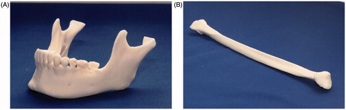
Thirty mandibular RP models were prepared with a 3D printer (ProJet 360, 3D Systems, Inc, Rock Hill, SC). These mandibular RP models were based on the mandibular CT data from 15 actual patients, and one identical pair of RP models per patient was produced. Of each pair, one was assigned to the experimental and the other to the control group (N = 15 mandibular RP models per group; ). Thirty identical fibular RP models were also produced (N = 15/group) with a 3D printer (ProJet 360, Rock Hill, SC), based on CT data from the left fibula of one patient ().
Figure 1. Experimental rapid prototype (RP) models. (A) Mandibular RP model. (B) Fibula RP model.
3D simulations of mandibular reconstructions with fibula grafts
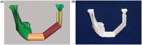
CT images of the mandibular RP models and the fibular RP models were acquired (1.0 mm slices; Siemens Sensation 64 CT scanner, Siemens AG, Erlangen, Germany). The DICOM files of the CT images were imported into the Mimics, version 14.0 software (Materialise, Leuven, Belgium). Then, 3D images of the mandible and fibula were reconstructed. It was assumed that, in all 15 mandibles, the left mandibular region was reconstructed. Thus, the simulated mandible was cut from the left condyle neck region to the right first premolar anterior region. The 3D fibula graft was positioned at the sectioned mandibular region and bent at the canine area and the angle area to reconstruct the mandible (). This simulation of the mandible reconstructed with the fibula was exported as a STL (.stl) file, and a 3D printer (CubeX, 3D Systems, Inc, Rock Hill, SC) was used to produce the reconstructed mandibular model (RP model), based on the simulation files ().
Figure 2. Mandibular reconstruction simulation and 3-D printed model. (A) The mandible was reconstructed with 3D imaging; the mandible was cut from the left subcondylar neck region to the right first premolar anterior region. Three-dimensional simulation of the mandible reconstruction with the fibula bony segments required bending the fibula at the canine area and at the angle area. This required three separate fibula segments: the anterior (light orange), the middle (brown), and the posterior (yellow) segments. (B) The reconstructed mandibular model was produced with a 3D printer, based on data from the simulated mandibular reconstruction with the fibula.
Reconstruction with the fibula cutting guide template: experimental group
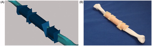
Fibula cutting guide templates were prepared according to the preoperative simulation plan. The fibula cutting guide was designed with Mimics software. First, the fibular bony segments that were bent or sectioned for the reconstruction were moved to their original positions in the fibula. Then, the cross-sectional data that represented each cut surface were used to create a template for guiding the cutting process. The guide was designed with the Boolean function of the Mimics software (). The guide was composed of a sleeve section that encircled the bone and a square sheet placed perpendicular to the bone that was turned to the angle of the cut. The sleeve was fixed to the bone for stabilization, and the flat side of the saw rested up against the sheet to position the saw blade at the correct angle. Then, the designed fibula cutting guide template was exported as a STL (.stl) file. Based on this file, a fibula cutting guide template was prepared with a 3D printer (Objet Eden260V, Stratasys, Eden Prairie, MN), and fixed onto the fibula model (). For cutting the fibula model, guided by the cutting guide template, sectioning was performed with a fissure bur, an industrial purpose thread saw and an osteotome.
Figure 3. Fibula cutting guide template. (A) The fibula cutting guide template was prepared, based on the computer-aided design of a mandibular reconstruction with the fibula. The template (dark blue) includes sleeves that wrap around the fibula, and small sheets (upright squares) that indicate the cutting angles. (B) The fibula cutting guide template was fixed to the intact fibula (RP model). The cutting guide template was prepared with a 3D printer and biomaterials.
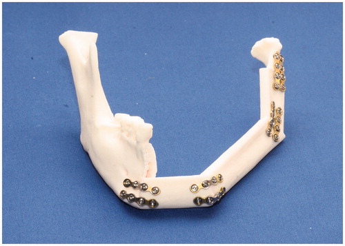
Next, the three bony fibula segments were fixed onto the resected mandibular models, starting from the anterior region of the mandible. Two titanium miniplates (Jaeil, Seoul, Republic of Korea) were used at each fixation site. Metal plating was performed at the right canine area and at the angle area (). The fibula bony segments were fixed, first to reconstruct the left mandibular canine area; then, the left mandibular body; and finally, the ramus region.
Figure 4. Experimental reconstruction of the mandibular RP model with fibula segments. The segments were cut with the manual method or with the STL fibula cutting guide. The metal miniplates are fixed to each joint.
Reconstruction by manually cutting the fibula (control group)
In the control group, the reconstructed mandibular RP model was used as a reference for fibula cutting. Osteotomy and reconstruction with the fibula were performed on all 15 mandibular RP models. First, the mandibular models were manually cut to the same size as the reconstructed RP mandible model. Then, the three fibula bony segments were cut, with the reconstructed RP mandible model as reference. Each fibula cut was marked with a fissure bur and cut with an industrial purpose thread saw and an osteotome.
With reference to the reconstructed RP mandibular model, a mandibular osteotomy was manually performed on each of the 15 mandible models to remove the appropriate region with an industrial purpose thread saw. The cuts were performed at the right premolar anterior region and the left subcondylar area. Metal plating was performed at the right canine area and the angle area, based on the reconstructed RP model as a reference. The miniplates were pre-bent, based on the reconstructed RP mandible model. The three fibula bony segments were adjusted and fixed onto the mandibular models (based on the reconstructed model), starting from the anterior region, with two titanium miniplates (Jaeil, Seoul, Republic of Korea) at each fixation site. As in the experimental group, the fibula bony segments were fixed, first to reconstruct the left mandibular canine area; then, the left mandibular body; and finally, the ramus region.
Registration between the preoperative surgical simulation and the actual experimental surgery
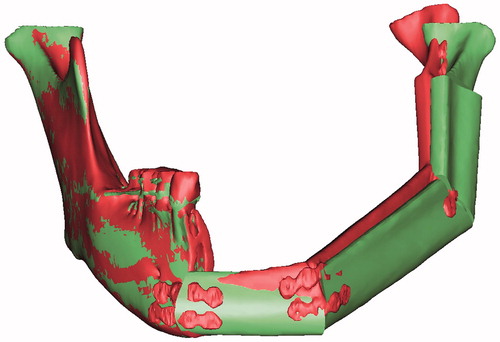
After performing the in vitro reconstructions with the fibulas, we obtained CT images of the 15 pairs of RP mandibles. The images were reconstructed as 3D images with the Mimics software and exported as STL files. The surgical simulation results were also exported as STL files. Then, XOV2 software (INUS Technology, Seoul, Republic of Korea) was used for registering the right mandibular regions, which were not modified in the surgical simulation or in the experimental mandibular reconstructions (). With reference to the right mandibular region, the postoperative STL file data were registered to the surgical simulation STL file data with a surface-based registration method. Then, these registered data were opened in the Mimics software and the results of the surgical simulation were compared with the results of the actual experimental surgery to calculate errors for the experimental and control groups.
Figure 5. The right mandibular regions were registered to compare data from two images. A comparison is shown between the surgical simulation (red) result and the postoperative result (green).
Reference planes, points and lines for measurement
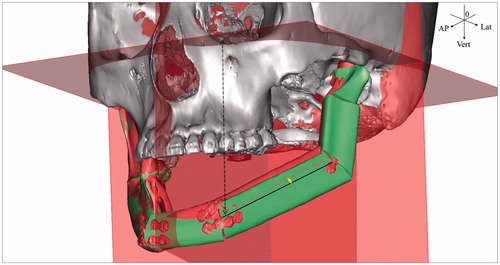
The registered data of the surgical simulation and the experimental surgery were opened in the Mimics software. Then, the distances were measured between a reference plane on the skull and data points on both the experimental reconstructed RP mandible and the surgical simulation result. At each point, the distances were compared to determine the difference between the model and the simulation. Three reference planes were chosen. The first reference plane was a Frankfort horizontal (FH) plane, positioned with reference to three points: the midpoint between the infraorbital rim margins on both sides (orbitale), and two points on the two external auditory canals (porion). The second reference plane was perpendicular to the FH plane. This mid-sagittal plane passed through the nasion and the internal occipital crest. The third reference plane was perpendicular to both the FH plane and the mid-sagittal plane. This coronal plane passed through the left porion. These three planes were used as references to measure the shortest distance from a point on the model to each plane, in the vertical, lateral and anteroposterior directions ().
Figure 6. Reference planes for measuring distances. The axes (e.g. blue lines; model, red dotted line; simulation in the middle segment) drawn through the shafts of the fibula fragments were set to measure the angular errors (e.g. yellow fan in the middle segment) in the fibula bone segments. Vertical distance errors were evaluated at the measurement points, with reference to the FH plane (e.g. black dotted arrow line; the vertical distance from the medial point on the middle segment). Anteroposterior distance errors were evaluated at the measurement points with reference to the coronal plane. Lateral distance errors were evaluated at the measurement points, with reference to the sagittal plane. The errors were determined by comparing the preoperative surgical simulation results to the postoperative results.
The measurement points on each model were the lateral points at both ends of the anterior fibula segment, which formed the anterior mandibular region; the lateral points at both ends of the second fibular bony segment, which formed the mandibular body; the lateral points at both ends of the third fibular bony segment, which formed the ramus region; and the lateral pole of the left condyle. One investigator marked equivalent measurement points on the experimental surgery model and on the surgical simulation. The shortest distance was measured from each point on the model to each plane, in the vertical, lateral and anteroposterior directions. In addition, the 3D distances between individual measurement points were measured.
To measure the angular position of the fibula bony segments, a line was drawn lengthwise, down the shaft of each fibula bony segment, connecting the lateral points on both ends (). The angles of the lines between the models and the simulations were determined at each fibula bony segment.
Statistics
A t-test was performed to compare and evaluate the distance errors in the mandibular reconstructions created with the two methods (the fibula cutting guide method and the manual fibula cutting method). A p value ≤0.05 was considered significant. To verify intra-operator errors, one measurement point was marked 15 times. The Dahlberg formula was used to verify the intra-operator error in the measurement point marking.
Results
The 3D distances were measured for the results from the preoperative computer simulation of the planned surgery and for the experimental surgical results on the postoperative RP models. The average difference in 3D distances between each model and the simulation were 9.87 ± 6.32 mm (mean ± SD), for the STL surgical guide method, and 14.76 ± 10.34 mm (mean ± SD), for the manual surgery; thus, the STL surgical guide incurred less error (p < 0.001) (). In both groups, the error increased from the anterior region to the posterior region. Both groups had an average distance error greater than 12 mm for the fibula segment corresponding to the posterior region of the mandibular body. In this region, the error was significantly greater with the manual method (17 mm–25 mm) than with the STL surgical guide method (12 mm–15 mm; ). The error was 24 mm or greater in the condyle region of the mandible with the manual method.
Table 1. Differences in 3-D distances (mm) between the simulated (planned) surgical result and two models created with different fibula cutting methods for mandibular reconstruction.
The angles of the lines connecting two ends of the individual fibula segments were measured. Each model segment was compared with that of the preoperative surgical simulation. In both methods, the error increased from the anterior region to the ramus region (). However, when the STL surgical guide was used, the angular errors at the middle segment (corresponding to the mandibular body) and at the posterior segment (corresponding to the mandibular ramus) were significantly smaller than the errors produced with the manual method. When the STL surgical guide was used, the angular errors were less than 10° to 13° at the posterior segment; in contrast, when the manual method was used, the angular errors were greatest at the posterior segment (about 21° error), and they were 10° or greater for all the segments.
Table 2. Axis angles (°) of the fibula segments between the simulated (planned) surgical result and two models created with different fibula cutting methods for mandibular reconstruction.
The vertical distances from the horizontal (FH) plane were measured in the preoperative surgical simulation and the postoperative experimental surgeries, and the differences were evaluated. The average errors were 3.59 ± 7.18 mm (mean ± SD) with the STL surgical template guide method and 8.58 ± 9.70 mm (mean ± SD) with the manual method (p < 0.001; ). Except for the medial point of the anterior segment and the condylar point, the vertical errors in both models increased from the anterior to the posterior segments. The positive values indicated that the reconstructed mandible was lower in the models compared to the position in the preoperative simulation. There was a large difference between the errors at the medial and distal points of the middle segment, which corresponded to the mandibular body. When the STL surgical template guide was used, these errors differed by about 6 mm, but when the manual method was used, the errors differed by as much as 11 mm. Starting at the distal point of the middle segment, the vertical errors to the condyle point were significantly smaller with the STL surgical template guide method than with the manual method (12 mm or greater). Furthermore, with the manual method, all the points were positive values, which indicated a lower vertical position than those in the surgical simulation. In contrast, with the STL surgical template guide method, the errors at the distal point of the anterior segment (−0.73 mm) and at the medial point at the middle segment (−1.04 mm) were negative, indicating that those points were shifted upwards compared to the simulation. This indicated that the manual method tended to shift the mandible towards the neck, and the STL surgical template guide method tended to shift the mandible away from the neck, compared to the simulation.
Table 3. Differences in vertical distances (mm) between the simulated (planned) surgical result and two models created with different fibula cutting methods for mandibular reconstruction.
The anteroposterior distances were measured with reference to the coronal plane, and the results were compared between the preoperative surgical simulation and the postoperative experimental surgery models. The average anteroposterior error was 3.15 ± 6.51 mm (mean ± SD) with the STL surgical template guide method and −1.32 ± 8.50 mm (mean ± SD) with the manual method (p < 0.001) (). With the STL surgical template guide method, all the points were shifted in the anterior direction (positive values) with respect to the simulation. In the manual method, all the points were shifted in the posterior direction (negative values) with respect to the simulation, except for the distal point of the anterior segment (0.61 ± 5.46 mm) and the medial point of the middle segment (0.20 ± 6.00 mm). With the STL surgical template guide method, the error continuously increased from the medial point of the anterior segment to the distal point of the middle segment. The largest anteroposterior error was 6.32 mm at the distal point of the middle segment, which represented the fibula used to reconstruct the mandibular body. With the manual method, the errors decreased significantly from the distal point of the anterior segment to the medial point of the posterior segment. The largest anteroposterior error was −4.65 mm at the distal point of the posterior segment, which represented the fibula used to reconstruct the ramus of the mandible. Between the distal point of the anterior segment and the medial point of the posterior segment, the errors were significantly lower with the manual method (range −1.25 mm–0.61 mm) than with the STL surgical template guide method (range 4.03 mm–6.32 mm).
Table 4. Differences in anteroposterior distances (mm) between the simulated (planned) surgical result and two models created with different fibula cutting methods for mandibular reconstruction.
The lateral errors were measured with reference to the sagittal plane. These errors were not significantly different between the STL surgical template guide and the manual methods (). In both groups, the medial point of the anterior segment, the distal point of the posterior segment, and the condylar point all showed positive values, which indicated errors in the outward lateral direction compared to the simulation. The distal point of the anterior segment, the medial point of the middle segment and the medial point of the posterior segment showed negative values, which indicated errors in the inward lateral direction compared to the simulation. With the STL surgical template guide method, the average lateral error at the distal point of the posterior segment was 3.11 mm, but it decreased to 1.45 mm at the condylar point. In contrast, with the manual method, the average lateral error at the distal point of the posterior segment was 6.82 mm, but it increased to 9.22 mm at the condylar point. The error at the condylar point was significantly different between the two methods (1.45 ± 4.01 mm versus 9.22 ± 10.11 mm for the STL surgical template guide versus the manual method; p = 0.013). The intra-operator error for marking the measurement point was 0.29 ± 0.08 mm (mean ± SD).
Table 5. Differences in lateral distances (mm) between the simulated (planned) surgical result and two models created with different fibula cutting methods for mandibular reconstruction.
Discussion
In the present study, we used RP models to compare the precision of two methods for cutting the fibula bone to use in a FFF mandibular reconstruction. Our results demonstrated that the surgical template cutting guide method incurred less error than the manual cutting method.
We found average 3D errors of 9.87 mm with the STL surgical template guide method and 14 mm with the manual method (p < 0.001). In both groups, the error increased from the anterior segment to the posterior segment. This might be due to the use of three fibula segments in the present study; thus, the errors at each region of contact between individual segments could have accumulated, which would cause the error to increase in the posterior direction. The increasing error could have arisen in part because the condyle head position was not fixed. In actual clinical surgeries, where the mandibular condyle head and the cranial bone are connected, this error might be reduced.
With the manual method, all the angular errors were 10° or more, and they were greater than the errors produced with the STL surgical template guide method. This could be explained either by the improved precision of the template guide tool or by the difficulty in precisely measuring the 3D axial angle with the naked eye.
In both groups, the vertical error increased from the anterior to the posterior regions, and the mandible position was lower than that of the preoperative simulation. The two methods were quite different in the distances measured for the medial and distal points of the middle segment, which corresponded to the mandibular body. The same bias could occur in clinical surgeries, even when a surgical guide is used.
The average anteroposterior error, with reference to the coronal plane, was significantly greater with the STL surgical template guide method than with the manual method. With the STL surgical template guide method, all the points were shifted in the anterior direction compared to the simulation. The greatest anteroposterior error was 6.32 mm at the distal point of the middle segment of the fibula, which corresponded to the mandibular body. Large errors most often occur when the position of the fibula segment is far from the remaining bony region after a mandibulectomy. With the STL surgical template guide method, the cut may have left a smaller gap between segments than that predicted in the simulation. Thus, the segments might be shifted slightly more anterior than predicted. It might be necessary to adjust the cutting thickness in a surgical simulation, based on the thickness of the saw used clinically.
In the manual method, most of the anteroposterior error values were negative, except at the distal point of the anterior segment and at the medial point of the middle segment. Negative values indicated that the points were shifted in the posterior direction compared to the preoperative surgical simulation. Based on these results, when the manual method is used in clinical settings, it may be necessary to measure the gap between fibula segments when they are fixed.
The lateral error, measured with reference to the sagittal plane, was similar with the two surgical methods. In both groups, positive error values were measured at the medial point of the anterior segment, the distal point of the posterior segment, and the condylar point, which indicated a shift in the outward direction (left of the simulation). In contrast, the negative error values measured at the distal point of the anterior segment, the medial point of the middle segment, and the medial point of the posterior segment indicated a shift in the inward direction (right of the simulation). These errors could have been caused by shifts at the contact points between the individual fibula segments, because the gaps between the segments were greater on the lateral sides than on the medial sides. In addition, in the condylar head and ramus region, the fibula segment was fixed with reference to the condylar head, which might have caused a small inward shift at the end of the segment of the ramus region. The errors at each contact point might have accumulated, which would have caused a large error at the lateral condyle site.
Recent studies on preoperative 3D surgical simulation planning used simulation results to prepare a surgical guide for application in the actual surgery.[Citation3,Citation4] Studies showed that, when the 3D surgical simulation planning was performed, the error between the bony segments could be decreased for mandibular reconstructions with the fibula.[Citation5,Citation6] When the mandibular reconstruction with the fibula was performed in patient groups with or without advance 3D surgical simulation planning for the plating, the results showed no significant difference between groups in the midline deviation; however, with advance simulation planned plating, less error was observed in the deviation at the condylar position, and the errors were partially reduced in the mandible body axis and the angular shift.[Citation7]
In the present study, we performed a preoperative 3D imaging surgical simulation, and, based on the simulation results, we prepared a reconstructed mandibular RP model with a 3D printer. Then, a mandibular reconstruction experiment was performed with reference to the prepared model. It was previously reported that the use of a mandible cutting guide and an RP template could improve the precision of mandible cutting and reconstruction.[Citation8] In a mandibular reconstruction with the fibula, Foley et al. reported that the average error was 2.7 mm at the condylar position and 2.5 mm at the gonial angle, when they used both a mandibular cutting guide and a fibula bone cutting guide, prepared with a 3D surgical simulation plan.[Citation1] However, in the present study, the error at the condylar position was large, despite our use of a STL surgical template guide. We found an average 3D distance error of 15.49 mm with the STL surgical template guide and 25.15 mm with the manual method at the condylar lateral point. Thus, our results were quite different from those of the previous clinical study. This may be due to the fact that the present study was conducted in RP models. Thus, unlike the actual clinical surgeries, in our experiments, the mandibular condylar head was not connected to the cranial bone, the temporomandibular joint was not taken into consideration, and only the error at the mandible was considered. Also, unlike Foley et al., we did not use a cutting guide for the mandible.
In the present study, our experiments were performed on mandibular RP models, and the cutting was performed with a manual, industrial purpose saw. Because the mandibular RP models could not always be perfectly cut and broken at the tip, the error at the cutting position could be greater than the error produced when this method is applied in a clinical setting. The surgical cutting template was perfectly suitable for the fibula RP models. However, in actual surgeries, other tissues are present; thus, additional adjustments could be required to position and fix the surgical cutting guide. In addition, when the sectioned bony segments were positioned, the operator manually fixed them by eye, without a precise fixation guide; thus, errors could have been made in the fixation procedure.
When the fibula was cut with the manual method for mandibular reconstruction, the operator cut the fibula by eye, and the plating and flap design were performed without computer assistance. Therefore, the errors in the surgical results depended on the mandibles and on the operator’s skill; however, in this study, the experiments were performed by a single operator. In addition, errors could be made during the plating, at the contact points between the mandible and the fibula anterior segment and between the fibula segments; these errors may depend on the contact angle or the presence of protruding parts. A separate cutting guide was not prepared for the mandibular models; therefore, errors could be made at the contact point between the cut mandible and the condylar head. However, because the mandible was cut with the manual method in both the experimental and the control groups, we assumed no significant difference between the two groups in the error associated with the cut mandible. Additional studies should be performed with a mandible cutting guide. In addition, the method of fixing the cutting guide should be examined to design a mandible cutting guide that is feasible for clinical applications.
In our experimental RP models, the condyle was not connected to the cranium; therefore, some errors we observed may be less likely to occur in the clinical setting. Further studies should be performed with experimental models that consider the temporomandibular joints and the soft tissue. Additional studies should also be conducted with the aim of designing a positioning guide to enable stable positioning of the fibula segments in the mandible. In mandibular reconstruction with a FFF, a mandible cutting template could improve the precision of the surgery. Further studies should investigate various error factors to determine how to modify the method for clinical applications with the use of various surgical guides, and for integration with an auxiliary navigation method.[Citation9–11]
In conclusion, our results are based on experiments with RP models of mandibles and fibulas. These RP mandibles were reconstructed with fibulas that were cut with either a surgical template guide or a manual method. We performed preoperative surgical simulation planning with CAD/CAM techniques, and we prepared a fibula surgical template guide with a 3D printer. In the mandibular reconstruction, better precision was achieved with fibulas cut with a surgical template guide than with fibulas cut with the manual method.
Funding information
This research was supported by the Basic Science Research Program, through the National Research Foundation of Korea (NRF), funded by the Ministry of Education (2013R1A1A2009251).
Disclosure statement
The authors declare no conflict of interest in this study.
References
- Foley BD, Thayer WP, Honeybrook A, et al. Mandibular reconstruction using computer-aided design and computer-aided manufacturing: an analysis of surgical results. J Oral Maxillofac Surg. 2013;71:e111–e119.
- Liu YF, Xu LW, Zhu HY, et al. Technical procedures for template-guided surgery for mandibular reconstruction based on digital design and manufacturing. Biomed Eng Online. 2014;13:63.
- Adolphs N, Liu W, Keeve E, et al. Craniomaxillofacial surgery planning based on 3D models derived from Cone-Beam CT data. Comput Aided Surg. 2013;18:101–108.
- Cartiaux O, Banse X, Paul L, et al. Computer-assisted planning and navigation improves cutting accuracy during simulated bone tumor surgery of the pelvis. Comput Aided Surg. 2013;18:19–26.
- Hou JS, Chen M, Pan CB, et al. Application of CAD/CAM-assisted technique with surgical treatment in reconstruction of the mandible. J Craniomaxillofac Surg. 2012;40:e432–e437.
- Zheng GS, Su YX, Liao GQ, et al. Mandibular reconstruction assisted by preoperative simulation and accurate transferring templates: preliminary report of clinical application. J Oral Maxillofac Surg. 2013;71:1613–1618.
- Mazzoni S, Marchetti C, Sgarzani R, et al. Prosthetically guided maxillofacial surgery: evaluation of the accuracy of a surgical guide and custom-made bone plate in oncology patients after mandibular reconstruction. Plast Reconstr Surg. 2013;131:1376–1385.
- Abou-ElFetouh A, Barakat A, Abdel-Ghany K. Computer-guided rapid-prototyped templates for segmental mandibular osteotomies: a preliminary report. Int J Med Robot. 2011;7:187–192.
- Adolphs N, Liu W, Keeve E, et al. RapidSplint: virtual splint generation for orthognathic surgery – results of a pilot series. Comput Aided Surg. 2014;19:20–28.
- Wong KC, Kumta SM, Sze KY, et al. Use of a patient-specific CAD/CAM surgical jig in extremity bone tumor resection and custom prosthetic reconstruction. Comput Aided Surg. 2012;17:284–293.
- Zhang W, Wang C, Shen G, et al. A novel device for preoperative registration and automatic tracking in cranio-maxillofacial image guided surgery. Comput Aided Surg. 2012;17:259–267.