ABSTRACT
Deficiencies with the current European reference method for the analysis using inductively couple plasma–mass spectrometry of metals in samples from stationary emissions sources are presented based on experimental data obtained from real samples. The effect of these deficiencies on the quality and accuracy of data is highlighted with biases of up to 40% being observed in real samples. Suggestions to improve the performance of the standard method are presented. In particular, the beneficial effect of using a drift correction procedure to account for the decrease in instrument sensitivity observed during an analytical measurement series is demonstrated. It is shown that this corrective procedure results in substantial improvements to the accuracy of data produced.
This work highlights the deficiencies in the analytical and quality control specifications of documentary standard methods for the determination of metals in stationary-source emissions and the systematic biases in analysis that can occur as a result. There are implications of this work for policy-makers and enforcement officers with respect to the real possibility of mistakes being made when gauging compliance with legislative emissions limits when using current methods. The solutions presented to ensure accurate measurements will be of interest to documentary standards experts and legislators to consider when the relevant standards are next revised.
INTRODUCTION
In many countries the emissions of pollutants from industrial stationary sources are regulated by legislation. These govern the allowable output of specified pollutants over a given time period with the aim of protecting human health, environmental sustainability, and terrestrial and aquatic biosystems. In Europe, the allowable output of industrial sources is broadly covered by the Integrated Pollution Prevention and Control (IPPC) Directive, including the Large Combustion Plants Directive, the Waste Incineration Directive (WID), the Solvents Emissions Directive, and three directives on titanium dioxide.Citation1 A key requirement of the WID is the requirement to ensure that the mass concentration of certain metals emitted is less than specified values over a sampling period of between 30 min and 8 hr (0.05 mg/m3 for Cd, Tl, and Hg; 0.5 mg/m3 for Sb, As, Pb, Cr, Co, Cu, Mn, Ni, and VCitation2). These metals can be particularly detrimental to human health and to the environment. In the United Kingdom, the Environment Agency regulates all incinerators that burn hazardous waste as well as other incinerators that burn nonhazardous waste at a rate of more than 1 t/hr. In addition, the Environment Agency operates their Monitoring Certification Scheme (MCERTS) to ensure the continued quality of environmental measurements of this type.Citation3 In Europe, the sampling and analytical measurement of metals is required to be performed by European reference method EN 14385.Citation4 Sampling of metals using this standard is onto quartz filters (for particulate-phase metals) and then into impingers containing an aqueous solution of nitric acid (HNO3) and hydrogen peroxide (for gaseous metals and those associated with very small particulate sizes passing through the filter). Additional samples are obtained from rinsing the sampling probe with an aqueous solution of HNO3. The filters and samples obtained from rinsing the sampling probes are then digested in hydrofluoric acid (HF) at elevated temperatures and pressures before analysis. The impinger solutions are measured without further digestion. The reference method allows analysis of the samples by atomic absorption spectroscopy, inductively coupled plasma–optical emission spectroscopy, or inductively coupled plasma–mass spec-trometry (ICP-MS). The work presented here highlights the possible deficiencies of the reference method that may be encountered when using ICP-MS for analysis of metals in emissions samples from stationary sources. It is shown that these deficiencies may seriously affect the quality and accuracy of the results obtained. A simple drift correction procedure is presented that, together with other method improvements, can be used to ensure the accuracy of results obtained using the European reference method.
Although there have been numerous studies of the effect on air quality and biosystems of metals emitted from industrial sources, there have only been a few detailing the technical challenges surrounding the estimation of metal emissions for emission inventoriesCitation5 and the measurement of metals emissions from stationary sourcesCitation6 but, to the best of the authors' knowledge, none developing the measurement science surrounding the analytical measurement of metals in emissions from stationary sources.
EXPERIMENTAL PROCEDURES
Sampling took place at two incinerator sites in England, both subject to the WID. Sampling from each point source took place according to the requirements of EN 14385 by the National Physical Laboratory (NPL)'s Stack Emissions Team, with MCERTS-qualified operatives using MCERTS-authorized procedures accredited by the U.K. Accreditation Service (UKAS) to International Organization for Standardization (ISO) 17025—“General Requirements for the Competence of Testing and Calibration Laboratories.” To summarize the method (which is described in detail, with diagrams describing the equipment setup, in EN 14385), sampling is via an isokinetic sampling train composed of a nozzle connected to a heated probe assembly that passes the sample through a heated quartz filter and then through a set of five impingers, the first three of which contain an absorption solution containing HNO3 (mass fraction of 0.033 g/g in water) and hydrogen peroxide (mass fraction of 0.015 g/g in water), the fourth impinger is left empty, and the fifth impinger contains silica gel desiccant. (Additional impingers containing different absorption solutions may be added to this arrangement if Hg is being sampled concurrently.) The eight samples obtained from each site included a sampled filter, the combination of contents from the first two impingers, the contents of the third impinger, the washings from the sampling probe (performed with HNO3 [mass fraction of 0.25 g/g in water]), and the respective blank equivalents of the four sample types described above—comprising simply the filter or impinger solutions without having undertaken any sampling.
Analysis was performed using NPL's in-house procedure for the ICP-MS analysis of metals in solution and on filters (which has been previously described in detailCitation7,Citation8) using a Perkin-Elmer Elan DRC II instrument. This method is UKAS accredited to ISO 17025 and is in accordance with the requirements of EN 14385 and EN 14902 (the European reference method for metals in ambient air that contains more robust quality control (QC) measures than EN 14385Citation9). All solutions were prepared gravimetrically using ultrahigh purity reagents (Fisher) and deionized water (Millipore, MilliQ). The impinger solutions were analyzed as received. The filters and probe washes were separately digested in a mixture of 2 mL of HF and 3 mL of HNO3 in a microwave oven (Anton Parr, Multiwave 3000). The resulting digest was mixed with 20 mL of boric acid (H3BO3) and diluted with deionized water. Quantification for Cd, Tl, Sb, As, Pb, Cr, Co, Cu, Mn, Ni, and V was performed against five gravimetrically prepared calibration standards, traceable to National Institute of Standards and Technology (NIST) Standard Reference Material (SRM) monoelemental standards and matrix matched to the relevant samples in question. The analytical measurement series consisted of samples, calibration standards, a QC solution, and a matrix blank. Each solution was measured in triplicate, with replicate measurements distributed approximately evenly throughout the measurement series, and with the QC solution measured every third sample. Interpolation was performed using NPL's XLGENLINE softwareCitation10 that allows generalized least-squares regression to be performed. The method was repeatedly validated against measurement of the certified reference material BCR038, “Fly Ash from Pulverised Coal.” Results throughout are presented as mass fractions of the relevant element in solution in units of nanograms per gram.
RESULTS AND DISCUSSION
The Observation of Instrumental Drift and Nonlinearity
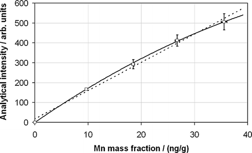
The matrices of the samples requiring analysis are complex and of high ionic strength. This is particularly true for the filter and probe wash digests. To some extent the effect of these matrices may be mitigated by diluting the digested solutions with deionized water, but too much dilution will adversely affect the method detection limits, and low levels of detection are required to prove unequivocally that emissions limits are being met—especially for short sampling times (the WID refers to a minimum sampling time of 30 min and a maximum of 8 hr). The first effect of these high-ionic-strength solutions is to induce a matrix effect in the ICP-MS measurement whereby the instrumental response to a given concentration of analyte is different in the complex sample matrix as opposed to in a simple deionized water matrix. In addition, significant nonlinearity is observed at higher analyte concentrations for the measurement of complex sample matrices as opposed to simple deionized water matrices. Although this is not a serious problem so long as matrix-matched calibration standards are used, it is worth noting that linear relationships are not always the most suitable to describe the calibration function. An example of this for a Mn calibration relationship in a stationary-source sample matrix is shown in , which clearly shows that a better calibration relationship is obtained with a quadratic (second-order) polynomial fit than with a linear (first-order) fit. The consequences of choosing the wrong calibration relationship may lead to very large relative biases at high concentrations and significant zero offsets at the low-concentration end of the curve.
Figure 1. The calibration relationship obtained for Mn in a stationary-source sample matrix showing a fit to a second-order polynomial (solid line; squared correlation coefficient r2 = 0.9997) and a first-order polynomial relationship (dotted line; r2 = 0.991). The calibration points are shown with their uncertainties at the 95% confidence level in the x- and y-axes.
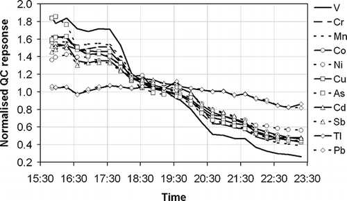
The second problematic effect of these high-ionic-strength solutions is to precipitate ionic salt material within the ICP-MS as a result of solvent evaporation and atomization during analysis—especially on the sample and skimmer cones, the ion lens, and the nebulizer tip. This causes dramatic reductions in the analytical sensitivity of the instrument over the course of a measurement run and necessitates a subsequent requirement to perform internal cleaning of the ICP-MS after each batch of analysis. Of course, this drift in sensitivity affects not only the high-ionic-strength solutions but also the impinger solutions that have a simpler matrix. The impinger solutions may alternatively be analyzed in a separate run to avoid sensitivity degradation for these samples, but this is more costly and time-consuming and does not solve the problem of the serious sensitivity degradation caused by the higher-ionic-strength solutions. The decrease in sensitivity observed over the course of a measurement series from the real sample set—containing 16 real samples from two U.K. incinerator sites, 5 calibration standards, 1 sample blank, all of the above analyzed in triplicate, and 1 QC solution analyzed every third sample during the measurement series—is shown in . As can be seen, the analytical sensitivity drops across the analytical series for all analytes, with Pb and Tl showing the smallest decreases and V showing the largest. (A possible explanation is that the heavier elements are less badly affected by the fouling of the ion lens, although this does not necessarily explain the relative lack of variability across all of the other elements measured.) However, all decreases are significant, with overall drops of 50% being observed from the start to the end of the run for all elements except Pb and Tl. To a small extent this drift is mitigated as a function of the final result being an average of the nature of the triplicate analysis of each sample and calibration standard. Hence, if a sample is analyzed at the start, middle, and end of the analysis series, the overall average is less dependent on drift than if the replicates of each of the samples were performed as consecutive analyses. However, this is not an acceptable mechanism to compensate for such a clear measurement deficiency and in practice does not work effectively because the analysis repeats are not always evenly spread out across the measurement series.
Figure 2. The analytical response of a QC sample of constant composition measured every third sample during an exemplar measurement series and normalized to the average response for each element (as indicated in the key) over the measurement period.
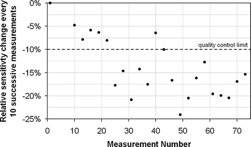
Although EN 14385 contains relatively little detail about the QC of the analytical procedure used, it does specify: “The calibration control solution should be measured frequently (e.g., after 10 sample measurements) to check the instrument drift. If the results of the calibration control solution are not within 10% of the certified values, correct the problem. If necessary, recalibrate the instrument and re-analyze the samples, starting from the last determination when the drift was within the 10% limit.” However, the drift observed in is so severe that, taking Co as an example, it is clear that it would be very difficult to pass this criterion on a regular basis. shows that after a short initial period of relatively stable operation with little negative drift, during which the EN 14385 criterion is met on five successive occasions, the drift becomes more severe and this quality criterion is only met twice in the 17 subsequent assessments. It is clear that stopping and restarting the measurement series under these circumstances would not help in meeting this drift criterion. A radically different approach is clearly needed to ensure the quality and accuracy of these measurements.
The Use of Internal Standards
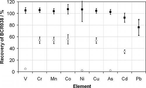
The effects of the instrument drift observed may be partially corrected using internal standardization, which allows intensity ratios, rather than absolute intensities, to be used for calibration—the assumption being that the target analyte and the internal standard drift at the same rate, and so the ratio of the two signals will be stable. This is not an ideal solution because the precision of the method will still become significantly poorer at longer measurement times, even if drift is reduced. Internal standardization is used successfully in ambient air analysis to compensate for the effects of short-term noise in higher-accuracy work.Citation6 Indeed the internal standardization approach is also recommended as a possible improvement by the U.K. Environment Agency's “Method Implementation Document [MID] for EN 14385.”Citation11 (MIDs have the role of supplementing standards methods with additional guidance or clarification to ensure they are implemented consistently within the MCERTS framework.) However, as the data in show, the use of internal standards in metals analysis from stationary sources is generally not possible. The use of internal standards supposes that the elements being used as internal standards do not occur at measurable concentrations within the sample under consideration. Emissions from stationary sources contain so many different elements for which the concentration may vary significantly over time that finding a suitable internal standard is very difficult. displays the recoveries obtained from the reference material BCR038, “Fly Ash from Pulverized Coal,” which is the most similar reference material currently available to the one used to validate the standard method, with and without the use of the commonly used internal standards Y (used for V, Ni, As), Ga (used for Cr, Mn, Co, Cu), Bi (used for Pb, Tl), and In (used for Cd, Sb), which were simultaneously introduced into the ICP-MS with the samples, calibration standards, and QC solution in approximately equal volumes via a mixing block. (The internal standards are intended to be as close as possible in mass to the analyte against which a ratio is taken to achieve maximum effectiveness.) Without the use of an internal standard, all of the elements in BCR038 are recovered satisfactorily in agreement with the certified value (although Pb is a little low). However, when internal standards are used, the recoveries are all less than 60% (except Pb), and those for V, Ni, and As are less than 10%. The magnitude of the effect observed for each element is highly correlated with the internal standard used. Pb is the only element in that uses Bi as an internal standard. It shows little sensitivity to the use of the internal standard because there is very little Bi in the reference material. On the other hand, there is clearly a significant amount of Y in the reference material because the elements that use Y as their internal standard (V, Ni, and As) all show dramatically reduced recoveries. The reason for this is the presence of significant concentrations of the internal standard elements in the samples themselves, yielding a much smaller-than-expected intensity ratio. When compared with calibration standards, which do not contain any of the elements in internal standards before their addition or co-introduction into ICP-MS, this results in a significant negative bias on measurement results. The use of very-high-concentration internal standards may reduce this problem to some extent. However, this is not generally recommended because the further that the sample-to-internal-standard intensity ratio moves away from unity, the less effective the internal standard correction becomes as a result of detector nonlinearity across orders of magnitude of intensity.
Figure 4. The recoveries determined from the measurement of BCR038 using standard method EN 14385 with (○) and without (•) the use of internal standards. The recoveries for Pb are overlapping. The error bars represent the overall uncertainty of the measurement at the 95% confidence interval. Both methods used the long-term drift correction procedure described in the text.
Moreover, it has been shown in that the observed decrease in instrument sensitivity during a measurement series is not the same for all analytes. In this way, the usefulness of internal standards that are different to the target analyte is severely limited. Equally, an element that is not present in the sample, such as Bi in the example above, would not be suitable for use as an internal standard for all elements being measured because the short-term noise and long-term drift characteristics of the internal standard and the sample will become more poorly matched as the difference in atomic mass between them increases, thereby significantly decreasing the beneficial effect of the internal standard. For all of these reasons, it is clear that on the basis of the drift characteristics of the analytes of interest, an alternative drift correction mechanism is required to ensure the validity of data produced using the European reference method.
Drift Correction Using QC Solutions
The use of QC solutions is mentioned in EN 14385 and in the MID for EN 14385, but in both cases this use is restricted to assessing pass/fail quality criteria. The authors now propose a superior use of these QC solutions that allows instrument drift to be properly corrected, ensuring the accuracy and robustness of results. The QC sample should contain all of the analytes of interest at roughly the same concentration and the same matrix as is expected in the unknown samples. The QC sample should then be measured at regular intervals in the measurement series. In the example considered here, every third measurement is a measurement of the QC solution. The series of values obtained from these measurements may then be used to correct for instrument drift. To summarize the correction method, which has been previously described and used in other arenasCitation12,Citation13: let ˆR QC equal the mean of the i measured responses from a series QC measurements, R QC,i. ˆR QC is then used nominally as an estimate of the “true” response from a QC measurement. The mean scaled deviations, R QC,i /ˆR QC, are then plotted in the time domain and fitted to a polynomial function, εdrift(t), in the time domain. (The order of the polynomial function has no physical meaning, but it is likely to be chosen with respect to goodness of fit. There is rarely any benefit in using anything above a fourth-order polynomial. The order of the polynomial must always additionally be substantially lower than the number of data points being fitted, although this is rarely a concern.) This polynomial function is then used to correct the series of non-QC measurements in the time domain (i.e., those of samples, calibration standards, and blanks in the measurement series), R(t), to give a series of corrected responses, R'(t), using Equationeq 1.
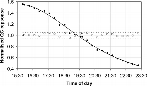
An example of this procedure used in practice for a series of Co measurements in the QC samples from the data shown in is shown in . This clearly demonstrates how a measurement series that showed initial sensitivities of 330% compared with those observed for the final measurement has been successfully corrected to be in all cases within 5% of the average value across the measurement series, with the best fit line through these corrected data suggesting a residual drift of less than 0.75% of the average value across the whole measurement series. Of course, this drift correction method makes the assumption that the intermediate samples will have drifted in the same manner as the QC sample and thus the correction for these samples has been equally effective. There is no reason to doubt that this is not the case given that the unknown samples and calibration standards are composed of the same matrix and same target analytes at similar concentrations. Indeed, analysis of the repeat measurements of nondrift-corrected real samples, albeit with fewer data points, confirms that the correction procedure is valid.
Figure 5. A series of measurements of Co (•) in the QC sample during a measurement series of real samples, calibration standards, and blanks, normalized to their average value during the measurement series. These measurements are fitted to a fourth-order polynomial function (black solid line; correlation coefficient: R2 = 0.996) and corrected according to Equationeq 1. The corrected data produced are also indicated (□) with the ±5% range indicated (gray dashed lines).
The frequency of the measurement of the QC solution can be tailored to the requirement for correction depending on the severity and nature of the drift observed. For analyses shown to exhibit relatively little drift, measurement of the QC solution may be less frequent. For situations in which drift is more severe, measurement of the QC solution should be regular enough to properly control the drift. (In the limiting case, the QC sample may be measured every other sample. In this case, there is the additional possibility of performing a drift correction on the basis of an assumed linear drift between two adjacent QC measurements. However, this generally results in more intensive and time-consuming data analysis and is probably in excess of fit-for-purpose requirements for the measurement of metals in emissions samples from stationary sources.) With automated measurement systems it is always easier to err on the side of higher-frequency measurements of QC solutions.
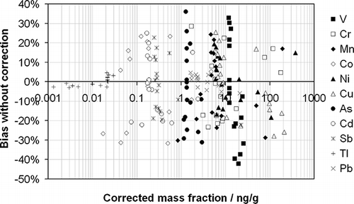
Using the drift correction procedure outlined above, the Co mass fractions of the real samples have been calculated as a demonstration of the effectiveness of the procedure. These have been compared against the uncorrected values in . The beneficial value of drift correction is clear. Without its use, relative deviations from the correct values of between +23 and −32% are observed, and the average absolute relative deviation from the corrected value for the data set considered is 16%. To highlight the effect of such discrepancies for uncorrected data, four pairs of samples and their corresponding blanks have been considered in –.
Figure 6. The corrected measured Co mass fractions as a function of the bias in the measured value, which would have been observed in the absence of correction, for the real samples considered in this study. Samples are presented as pairs (linked by the dashed lines) of sampled material (•) and their corresponding blank (○). Four exemplar pairs—a through d—are highlighted and discussed further in the text.
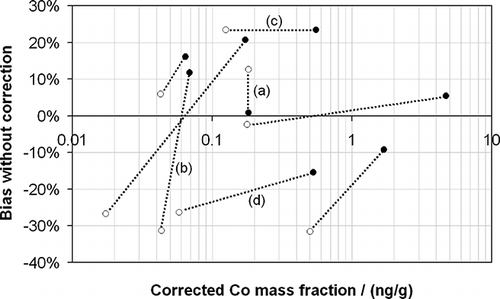
| • | Measurement pair a shows a situation in which there is very little if any Co in the sample taken from the stationary source as compared with its corresponding blank (both having corrected mass fractions of 0.18 ng/g). However, without correction, the blank measurement would have been 13% higher, but the sample measurement would have been only 1% higher, giving the very confusing and unsatisfactory impression that there was more Co in the blank than the material collected from the stationary source—possibly indicating, erroneously, a contamination issue. | ||||
| • | Measurement pair b represents a situation in which relatively little Co is present in the sample as compared with the blank, but without correction it would have seemed that there was substantially more Co emitted from the stationary source than was actually the case. This is a result of the sample having a large positive bias and the blank displaying a large negative bias. In this type of case it is possible that the results would erroneously indicate that an emissions limit had been breached. | ||||
| • | Measurement pair c, in which the blank and sample measurements have a large positive bias, represents an example in which without correction the measurement results may have erroneously indicated an exceedence of emissions limits or that the blank measurement may have been unacceptably high and the measurement result discarded. | ||||
| • | Measurement pair d, in which blank and sample measurements have a large negative bias, represents an example in which without correction the measurement results may have erroneously indicated that an emissions limit had been met, when in reality it had not, or that the blank measurement may have been acceptable, but in reality it may have been too high and the measurement result should have been discarded. | ||||
The deviations observed for the entire set of elements measured in these real samples are shown in . These data are summarized numerically in . It is apparent from that the range of mass fractions over which analysis is required for metals from stationary sources spans 6 orders of magnitude—a challenge for any analytical system, not least for one that is showing significant drift. It is notable from that the range of bias incurred if the drift correction procedure is not used is relatively similar across the elements measured (between approximately +25 and −25%), except for Tl and Pb, in which the observed biases are approximately 5 times smaller. Of course, this is a direct function of the observation in that Tl and Pb suffered considerably less drift during the course of the measurement series than the other elements. The average absolute relative bias shows a similar pattern with an overall average of 13% (or 15% if Tl and Pb are excluded). The average relative biases observed are less than 3% (except for As and V), which is a function of the measurements of each sample being generally spread evenly across the measurement series such that as many experience a positive bias as experience a negative bias.
Table 1. The observed range of relative bias without drift correction, the average relative deviation, and the average absolute relative deviation for each of the elements measured in the real stationary-source samples displayed in
CONCLUSIONS
Data highlighting the issues encountered when making measurements of the metal content of stationary-source emissions samples with analysis using ICP-MS and following the EN 14385 reference method were presented. It was noted that the origin of the measurement issues encountered originates from the high ionic content of the sample and the likelihood of this detrimentally affecting the sensitivity of the ICP-MS over time. It was shown that without correction this could result in significant biases in measurement results of up to 40% (relative), which may lead to incorrect conclusions being drawn about compliance with emissions directives. A simple drift correction mechanism that is based on the repeated measurement of a QC solution throughout the measurement series was used to correct the measurement results and this proved to be extremely effective, reducing the observed drift to almost zero. The effect of this procedure on real samples was demonstrated. It was additionally observed that internal standards should not be used with samples being analyzed for metals from stationary sources because they are likely to contain at least some of the internal standards at significant concentrations, resulting in serious underestimates of the content of unknown samples. Furthermore, it was noted that another effect of the high-ionic-strength matrix is the observation of significant nonlinearity in calibration relationships.
The EN 14385 reference method provides relatively little guidance or performance specifications for the analytical part of the procedure. Although the additional information in the MID for EN 14385 is useful, it does not address the collection of measurement problems elucidated in this work. Therefore, the following suggestions, not covered in the existing documentary guidance, are now proffered to ensure accurate and fit-for-purpose metal analysis from stationary-source samples:
| • | The matrix of all calibration standards, QC solutions, and blank solutions should be as closely matched as possible to that of the samples in all cases. | ||||
| • | The order of polynomial providing the best least-squares fit should be selected when establishing a calibration relationship. This may be a polynomial of order 2 rather than a linear relationship. | ||||
| • | The use of internal standards should be avoided unless it has first been proven that the elements being used as internal standards are not present in the samples. (Even then, it should be recognized that the drift rate of each element is unlikely to be equal.) | ||||
| • | Samples should be diluted with deionized water before analysis to limit the degradation of analytical sensitivity during the measurement series. The extent of dilution should not adversely compromise the detection limits of the method in terms of assessing compliance with emissions legislation. | ||||
| • | A QC solution of similar matrix and composition to a representative sample should be analyzed throughout the measurement series at a frequency defined by the severity of the observed drift in analytical sensitivity. Correction of the analytical responses should then be performed using the method described in the text. | ||||
| • | To further improve the robustness of the drift correction method, it is suggested that repeat analyses of samples are distributed as evenly as possible throughout the measurement series so that there is additionally some natural “averaging-out” of the effect of the drift (i.e., a measurement series consisting of two repeats of each sample should be, in order, A-B-C-D-E-A-B-C-D-E and not A-A-B-B-CC-D-D-E-E). | ||||
Given that the MID for EN 14385 also allows Hg to be measured in stationary-source samples as long as the requirements of the EN 13211Citation14 (which calls upon EN 1483Citation15 for analysis) are met, it is therefore clear that the conclusions reached in this paper and the recommendations proffered should equally apply to the analysis of Hg in emissions samples using ICP-MS.
It is hoped that the recommendations made in this paper will receive fulsome consideration when EN 14385 and related documentation are reviewed and redrafted in the future, especially with respect to analysis by ICP-MS.
ACKNOWLEDGMENTS
The U.K. Department of Business, Innovation, and Skills funding of the National Measurement System's Chemical and Biological Metrology Programme is gratefully acknowledged. The use of the NPL Radioactivity Group's HF digestion facility is gratefully acknowledged.
REFERENCES
- 2010 . European Commission. Directive 2010/75/EC of the European Parliament and of the Council of 24 November 2010 on Industrial Emissions (Integrated Pollution Prevention and Control) . Off. J. Euro. Union , L334 : 17 – 119 .
- 2000 . European Commission. Directive 2000/76/EC of the European Parliament and of the Council of 4 December 2000 on the Incineration of Waste . Off. J. Euro. Union , L332 : 1 – 31 .
- MCERTS Air Scheme http://www.s-t-a.org/mcerts/ (http://www.s-t-a.org/mcerts/) (Accessed: 1 January 2011 ).
- 2004 . EN 14385 Stationary Source Emissions—Determination of the Total Emission of As, Cd, Cr, Co, Cu, Mn, Ni, Pb, Sb, Tl, and V , Brussels , , Belgium : European Committee for Standardization .
- Bhanarkar , A.D. , Rao , P.S. , Gajghate , D.G. and Nema , P. 2005 . Inventory of SO2, PM and Toxic Metals Emissions from Industrial Sources in Greater Mumbai, India . Atmos. Environ. , 39 : 3851 – 3864 .
- Necsulescu , C. , Ionita , L. and Bucur , E. 2008 . Stationary Sources Emissions. Total Cd, Cr, Cu Determination in Exhaust Gases from Incinerators . J. Environ. Prot. Ecol. , 9 : 1 – 14 .
- Brown , R.J.C. , Yardley , R.E. , Brown , A.S. and Milton , M.J.T. 2004 . Sample Matrix and Critical Interference Effects on the Recovery and Accuracy of Concentration Measurements of Arsenic in Ambient Particulate Samples Using ICP-MS . J. Anal. Atom. Spectrom. , 19 : 703 – 705 .
- Brown , R.J.C. , Goddard , S.L. , Brown , A.S. and Yardley , R.E. 2008 . The Effect of Isotopic Composition on the Uncertainty of Routine Metal Mass Concentration Measurements in Ambient Air . J. Auto. Methods Manage. Chem. , 2008 doi:10.1155/2008/504092
- 2005 . EN14902 Ambient Air Quality—Standard Method for the Measurement of Pb, Cd, As, and Ni in the PM10 Fraction of Suspended Particulate Matter , Brussels , , Belgium : European Committee for Standardization .
- Smith , I. Software for Determining Polynominal Calibration Functions by Generalised Least Squares . National Physical Laboratory (NPL) Report MS11 . 2010 . NPL: Teddington, United Kingdom
- 2010 . Method Implementation Document for EN 14385, Version 2.1 , London , , United Kingdom : Environment Agency .
- Salit , M.L. and Turk , G.C. 1998 . A Drift Correction Procedure . Anal. Chem. , 70 : 3184 – 3190 .
- Brown , A.S. , Brown , R.J.C. , Corns , W.T. and Stockwell , P.B. 2008 . Establishing Si Traceability for Measurements of Mercury Vapour . Analyst , 133 : 946 – 953 .
- 2001 . EN 13211 Air Quality. Stationary Source Emissions—Manual Method of Determination of the Concentration of Total Mercury , Brussels , , Belgium : European Committee for Standardization .
- European Committee for Standardization, EN 1483 Water quality-Determination of mercury. Method using atomic absorption spec-trometry. CEN, Brussels, 2007.
